
mud pump pressure calculation free sample
Pumps tend to be one of the biggest energy consumers in industrial operations. Pump motors, specifically, require a lot of energy. For instance, a 2500 HP triplex pump used for frac jobs can consume almost 2000 kW of power, meaning a full day of fracking can cost several thousand dollars in energy costs alone!
So, naturally, operators should want to maximize energy efficiency to get the most for their money. Even a 1% improvement in efficiency can decrease annual pumping costs by tens of thousands of dollars. The payoff is worth the effort. And if you want to remotely control your pumps, you want to keep efficiency in mind.
In this post, we’ll point you in the right direction and discuss all things related to pump efficiency. We’ll conclude with several tips for how you can maintain pumping efficiency and keep your energy costs down as much as possible.
In simple terms, pump efficiency refers to the ratio of power out to power in. It’s the mechanical power input at the pump shaft, measured in horsepower (HP), compared to the hydraulic power of the liquid output, also measured in HP. For instance, if a pump requires 1000 HP to operate and produces 800 HP of hydraulic power, it would have an efficiency of 80%.
Remember: pumps have to be driven by something, i.e., an electric or diesel motor. True pump system efficiency needs to factor in the efficiency of both the motor AND the pump.
Consequently, we need to think about how electrical power (when using electric motors) or heat power (when using combustion engines) converts into liquid power to really understand pump efficiency.
Good pump efficiency depends, of course, on pump type and size. High-quality pumps that are well-maintained can achieve efficiencies of 90% or higher, while smaller pumps tend to be less efficient. In general, if you take good care of your pumps, you should be able to achieve 70-90% pump efficiency.
Now that we have a better understanding of the pump efficiency metric, let’s talk about how to calculate it. The mechanical power of the pump, or the input power, is a property of the pump itself and will be documented during the pump setup. The output power, or hydraulic power, is calculated as the liquid flow rate multiplied by the "total head" of the system.
IMPORTANT: to calculate true head, you also need to factor in the work the pump does to move fluid from the source. For example, if the source water is below the pump, you need to account for the extra work the pump puts in to draw source water upwards.
*Note - this calculation assumes the pump inlet is not pressurized and that friction losses are minimal. If the pump experiences a non-zero suction pressure, or if there is significant friction caused by the distance or material of the pipe, these should be factored in as well.
Every foot of water creates an additional 0.434 PSI of pressure, so we"ll find the elevation head by converting the change in elevation in feet to the suction pressure created by the water.
You"ll notice that the elevation head is minimal compared to the discharge pressure, and has minimal effect on the efficiency of the pump. As the elevation change increases or the discharge pressure decreases, however, elevation change will have a greater impact on total head.
Obviously, that’s a fair amount of math to get at the pump efficiency, considering all of the units conversions that need to be done. To avoid doing these calculations manually, feel free to use our simple pump efficiency calculator.
Our calculations use static variables (pump-rated horsepower and water source elevation) and dynamic variables (discharge flow and pressure). To determine pump efficiency, we need to measure the static variables only once, unless they change.
If you want to measure the true efficiency of your pump, taking energy consumption into account, you could add an electrical meter. Your meter should consist of a current transducer and voltage monitor (if using DC) for electrical motors or a fuel gauge for combustion. This would give you a true understanding of how pump efficiency affects energy consumption, and ultimately your bank account.
Up until this point, we’ve covered the ins and outs of how to determine pump efficiency. We’re now ready for the exciting stuff - how to improve pump efficiency!
One of the easiest ways to improve pump efficiency is to actually monitor pumps for signs of efficiency loss! If you monitor flow rate and discharge (output power) along with motor current or fuel consumption, you’ll notice efficiency losses as soon as they occur. Simply having pump efficiency information on hand empowers you to take action.
Another way to increase efficiency is to keep pumps well-maintained. Efficiency losses mostly come from mechanical defects in pumps, e.g., friction, leakages, and component failures. You can mitigate these issues through regular maintenance that keeps parts in working order and reveals impending failures. Of course, if you are continuously monitoring your pumps for efficiency drops, you’ll know exactly when maintenance is due.
You can also improve pump efficiency by keeping pumps lubricated at all times. Lubrication is the enemy of friction, which is the enemy of efficiency (“the enemy of my enemy is my friend…”).
A fourth way to enhance pump efficiency is to ensure your pumps and piping are sized properly for your infrastructure. Although we’re bringing this up last, it’s really the first step in any pumping operation. If your pumps and piping don’t match, no amount of lubricant or maintenance will help.
Pipes have physical limits to how much fluid they can move at a particular pressure. If pipes aren’t sized properly, you’ll lose efficiency because your motor will have to work harder. It’s like air conditioning - if your ductwork isn’t sized appropriately for your home, you’ll end up paying more on your energy bill.
In this post, we’ve given you the full rundown when it comes to calculating and improving pump efficiency. You can now calculate, measure, and improve pump efficiency, potentially saving your business thousands of dollars annually on energy costs.
For those just getting started with pump optimization, we offer purpose-built, prepackaged solutions that will have you monitoring pump efficiency in minutes, even in hazardous environments.

This approach works well but relying on a printed reference is not without the risk since the wrong value can still be selected from the fine print of a reference table, or the reference document can be damaged or lost (e.g., dropped in the mud pit) altogether.
So, let’s address the alternative approach of using simple mathematical formulas to determine the same information. Although the reliance on a single sheet of paper to obtain the needed value is avoided with this approach, the potential for human error or miscalculation remains, meaning regardless of the approach, great care in determining such values is prudent.
As we consider the various calculations that enable us to determine the values of length, weight, pressure, volume, flow velocity, etc., we should remain mindful of the units of measure we’re dealing with. The groundwater industry uses units of measure that are somewhat intermingled with other units from associated disciplines such as engineering, surface water hydrology, and the oil and gas drilling industry.
We want to know the volume of material (filter pack sand, cement grout, etc.) that is to be placed in the annulus to assure the annular void has been properly and completely filled (Figure 1). The conceptual diagram showing the variables used for calculating an annular void is shown in Figure 2, and the formula for the annular volume calculation is:
In this calculation, the “d” value is the diameter of the casing or pipe diameter, and the “D” value is the borehole diameter (Figure 2). The sump area below the base of the casing has only one diameter in the open borehole, so the “d” value is omitted, and the formula just becomes:
If excessive hydraulic pressures are exerted on a well casing, it will collapse. We generally know the collapse strength of the well casing from the casing supplier or from standard references such as the charts in American Water Works Association Standard A100. The hydraulic pressures applied to the outside of the well casing depend on the density of the liquid and the depth of submergence (Figure 1). Applying the fluid density (measured in the field) and depth (Figure 2), the formula for hydraulic pressure head calculation is:
The hydraulic head formula is applicable to the hydraulic pressure head for any liquid, but we most commonly use this calculation during cement seal installation, since cement grout is generally the heaviest liquid being introduced to the annulus during well construction.
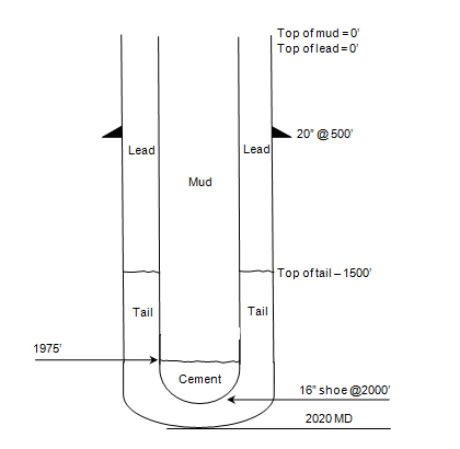
The intermediate casing can be sealed using the pressure grouting technique (Figure 3) to pump cement slurry down through the drill pipe and out to the annulus through a float shoe (a drillable check valve connected to the base of the casing). The inside of the intermediate casing is kept full of water during the cement placement to equilibrate hydraulic pressures inside and outside the casing. After the intermediate casing is sealed with the pressure grouted cement, the float shoe can be drilled out and the borehole advanced for installation of the screen and filter pack in the lower part of the well.
Floating of a casing string introduces serious logistical and safety hazards and creates significant disruption to the integrity of the annular seal. The potential for floating of the intermediate casing can be easily mitigated by securing it at the land surface, but the driller needs to know that this is required before the cementing operations begin. Thus, a buoyancy calculation is a good idea prior to pressure grouting operations as illustrated in Figure 3.
The buoyancy calculation is more of a conceptual comparison than a pure mathematical formula. This analysis involves some visualization be made on the part of the groundwater professional.
If you apply the weight calculations for a 400-foot-long steel casing with a 16-inch diameter and a 5/16-inch wall thickness, which is filled with water, you’ll see that the downward force in this example is only 52,982 pounds. Thus, the casing in this example will float. The lesson from this counterintuitive scenario is that a casing can actually float. (I’ve seen it happen, and trust me, you don’t want to).
There are several calculations that are commonly applied by drilling fluid engineers (mud engineers) to determine the time period required for the fluid to move from one location in the borehole to another. Some of the more common equations are described below.
The uphole velocity calculation provides a determination of the speed at which the drilling mud will flow as it moves up the borehole. For direct air rotary or reverse circulation drilling methods, the uphole velocity is high, so this calculation is generally applicable only for the direct mud-rotary drilling method. The formula for uphole velocity is:
Notice the uphole velocity formula is similar to the annular volume formula in that both those calculations use the factor (D2 – d2) to address the cross-sectional area of the annulus. However, the constants in these two formulas are different (0.005454 versus 24.51), which can be confusing. Keep in mind, however, that the constants primarily just provide unit conversions.
Thebottoms-up time calculation enables us to determine the time period for the drilling fluid (and the cuttings it is carrying) to travel from the drill bit up to the land surface. This is illustrated in Figure 6(A).
We can calculate the bottoms-up time by using the uphole velocity formula with the borehole depth and drilling mud flow rate plugged in, but that flow rate is being generated by the mud pump, and positive displacement mud pumps (duplex or triplex) are almost never equipped with a flow meter. To determine the flow coming from the mud pump, we can use the formulas:
Remember the strokes are counted in both the forward and backward directions on a duplex pump, but only in the forward direction on a triplex pump. Drillers often have reference charts that provide oilfield barrels per stroke (bbl/stroke), which can be converted to gpm by timing the strokes per minute and converting barrels to gallons (1 barrel = 42 gallons).
The round-trip time enables us to see the result of drilling fluid additives, as indicated by the return flow of fluids at the land surface, as is illustrated in Figure 6(B). The round-trip time calculation is the same as bottoms-up time, but with the travel time of fluid to displace the drill pipe added in.
A specified volume of drilling fluids (called a pill) can be circulated to a particular depth interval within the borehole (called spotting), so that the additives in the pill of drilling mud can address the borehole problem at a particular depth of the borehole. This is shown in Figure 6(C).
The calculation for time required to spot a pill of drillingfluid involves determining the pumping time (at the calculated flow rate) required to displace the fluid so that the drilling mud additives are located adjacent to the problematic interval. This approach is used by mud engineers to address problems such as lost circulation or stuck drill pipe.
The formulas and calculations provided in this column and elsewhere provide important tools for us to quantify the variables we need for water well design and construction. However, it is important to remember that “doing the math” is not a replacement for applying professional knowledge and consideration to determine whether the mathematical result makes common sense.
A few years ago, I received a call from a contractor asking for help mitigating a situation with a governmental transport agency in regards to monitoring downhole pressures as they were drilling under a six-lane highway crossing. They were asked to provide details on the drilling fluid they were using and the expected annular pressure while drilling. In order to do this, one must look at the functions of the drilling fluids, the properties of the drilling fluids (like viscosity and solids content), the volume of fluids being pumped, and the rate or speed of drilling.
You may be wondering what this has to do with fluid volumes and downhole pressure? The answer is quite a bit, based on the properties of the fluid being used. The contractor needs to look at the primary properties of the fluid, which are:
The higher the viscosity of the fluid, the higher the pump pressure required and the higher the downhole pressure. As the fluid is designed to suspend and transport cuttings, the amount of fresh fluid being pumped will directly affect the solids content of the fluids being displaced out of the hole. Lastly, the pressure of the drilling fluid, encapsulated by the filter cake against the formation, helps hold the hole open. The filter cake controls the fluid loss with positive pressure; however, it must be controlled in order to not exceed downhole pressure.
Therefore, looking at this example, we know that we need to move 1.02 gallons of soil per linear foot of bore. In order to do this, enough drilling fluids need to be pumped downhole in order to produce a flowable slurry. As mentioned earlier, the viscosity and solids content must be controlled in order to keep the downhole pressure manageable. In fact, a ratio of 2:1 to 3:1 of fluids per gallon of soil is needed in sand, and in clay the ratio may be up to 5:1. For example, if drilling in sand, a 2:1 ratio will be required as a minimum to produce a flowable slurry that will carry the cuttings out of the borehole. In this example, roughly 2-gallons of drilling fluid will need to be pumped per linear foot. As the diameter of the borehole increases, the amount of fluid required increased dramatically. For example, the calculation for a bore done by a 10-inch reamer is:
Without taking into account any pilot or pre-ream, the volume of soils we need to remove is 4.08 gal./ft. Therefore, in sand, we need to pump a minimum of 8.16 gal./ft. of drilling fluids to effectively displace the cuttings.
When pulling a pipe through the borehole, it is essential that the proper volume of slurry is pumped and also that there is sufficient annular space to allow for flow of the slurry. The volume of the fluid will keep the viscosity and solids content low and the slurry flowable. Without creating a flowable slurry, circulation will be lost and pressure in the borehole will increase rapidly, resulting in either a break-off or stuck pipe and/or inadvertent returns at the surface.
This now brings us to downhole pressures. The calculations of recommended downhole pressures are only as good as the geotechnical reports the contractor has. Often the engineering documents will recommend an annular pressure not to be exceeded. There is also software available that can produce this data. It is common that the available geotechnical soil reports were taken from the entry pit and the exit pit or nearby, but not necessarily along the entire planned bore path. Therefore, there can be unknown ground formations along the bore that the contractor may be unaware of unless he or she has drilled in the same area before.
In this equation, 0.052 is a unit conversion factor. It means that hydrostatic pressure (P), the result of the equation, is expressed in units of psi.
The contractor I mentioned at the beginning of this column wanted some assistance to maintain downhole pressure in order to not cause formation damage while drilling under the roadway. The reality is that, in order to do this, the contractor needs to fully understand and ensure the following: the drilling fluid’s functions and properties match the soil type; flow rate requirements are understood; and the speed of the drilling is known and monitored, all while keeping circulation constant.
A small- to medium-sized HDD driller has some options to understand the downhole pressure while drilling. On critical pullbacks, there is special instrumentation that can be installed between the reamer and the pullback string. This instrumentation can provide real-time annular pressure readings. The speed of the drilling and volume of fluids can be regulated to keep pressure consistent and below a pre-determined value. Another option is for the driller to continually measure the mud weight of the fluid returns at the exit pit. The weight of the returns can be an indicator of the downhole pressure. The higher the mud weight, the higher the annular pressure.
Spending the time to understand the fluids required, the volume and speed of drilling, and the resultant annular pressure can make the difference between success and failure. This knowledge results in bores completed on time and on budget. Keep on turning to the right!

When choosing a size and type of mud pump for your drilling project, there are several factors to consider. These would include not only cost and size of pump that best fits your drilling rig, but also the diameter, depth and hole conditions you are drilling through. I know that this sounds like a lot to consider, but if you are set up the right way before the job starts, you will thank me later.
Recommended practice is to maintain a minimum of 100 to 150 feet per minute of uphole velocity for drill cuttings. Larger diameter wells for irrigation, agriculture or municipalities may violate this rule, because it may not be economically feasible to pump this much mud for the job. Uphole velocity is determined by the flow rate of the mud system, diameter of the borehole and the diameter of the drill pipe. There are many tools, including handbooks, rule of thumb, slide rule calculators and now apps on your handheld device, to calculate velocity. It is always good to remember the time it takes to get the cuttings off the bottom of the well. If you are drilling at 200 feet, then a 100-foot-per-minute velocity means that it would take two minutes to get the cuttings out of the hole. This is always a good reminder of what you are drilling through and how long ago it was that you drilled it. Ground conditions and rock formations are ever changing as you go deeper. Wouldn’t it be nice if they all remained the same?
Centrifugal-style mud pumps are very popular in our industry due to their size and weight, as well as flow rate capacity for an affordable price. There are many models and brands out there, and most of them are very good value. How does a centrifugal mud pump work? The rotation of the impeller accelerates the fluid into the volute or diffuser chamber. The added energy from the acceleration increases the velocity and pressure of the fluid. These pumps are known to be very inefficient. This means that it takes more energy to increase the flow and pressure of the fluid when compared to a piston-style pump. However, you have a significant advantage in flow rates from a centrifugal pump versus a piston pump. If you are drilling deeper wells with heavier cuttings, you will be forced at some point to use a piston-style mud pump. They have much higher efficiencies in transferring the input energy into flow and pressure, therefore resulting in much higher pressure capabilities.
Piston-style mud pumps utilize a piston or plunger that travels back and forth in a chamber known as a cylinder. These pumps are also called “positive displacement” pumps because they literally push the fluid forward. This fluid builds up pressure and forces a spring-loaded valve to open and allow the fluid to escape into the discharge piping of the pump and then down the borehole. Since the expansion process is much smaller (almost insignificant) compared to a centrifugal pump, there is much lower energy loss. Plunger-style pumps can develop upwards of 15,000 psi for well treatments and hydraulic fracturing. Centrifugal pumps, in comparison, usually operate below 300 psi. If you are comparing most drilling pumps, centrifugal pumps operate from 60 to 125 psi and piston pumps operate around 150 to 300 psi. There are many exceptions and special applications for drilling, but these numbers should cover 80 percent of all equipment operating out there.
The restriction of putting a piston-style mud pump onto drilling rigs has always been the physical size and weight to provide adequate flow and pressure to your drilling fluid. Because of this, the industry needed a new solution to this age-old issue.
As the senior design engineer for Ingersoll-Rand’s Deephole Drilling Business Unit, I had the distinct pleasure of working with him and incorporating his Centerline Mud Pump into our drilling rig platforms.
In the late ’90s — and perhaps even earlier — Ingersoll-Rand had tried several times to develop a hydraulic-driven mud pump that would last an acceptable life- and duty-cycle for a well drilling contractor. With all of our resources and design wisdom, we were unable to solve this problem. Not only did Miller provide a solution, thus saving the size and weight of a typical gear-driven mud pump, he also provided a new offering — a mono-cylinder mud pump. This double-acting piston pump provided as much mud flow and pressure as a standard 5 X 6 duplex pump with incredible size and weight savings.
The true innovation was providing the well driller a solution for their mud pump requirements that was the right size and weight to integrate into both existing and new drilling rigs. Regardless of drill rig manufacturer and hydraulic system design, Centerline has provided a mud pump integration on hundreds of customer’s drilling rigs. Both mono-cylinder and duplex-cylinder pumps can fit nicely on the deck, across the frame or even be configured for under-deck mounting. This would not be possible with conventional mud pump designs.
The second generation design for the Centerline Mud Pump is expected later this year, and I believe it will be a true game changer for this industry. It also will open up the application to many other industries that require a heavier-duty cycle for a piston pump application.


 8613371530291