
mud pump pressure calculation brands

Rig pump output, normally in volume per stroke, of mud pumps on the rig is one of important figures that we really need to know because we will use pump out put figures to calculate many parameters such as bottom up strokes, wash out depth, tracking drilling fluid, etc. In this post, you will learn how to calculate pump out put for triplex pump and duplex pump in bothOilfield and Metric Unit.
NOTE: Max RPM in the above equation varies according to type of pump, size of stroke, and other variables. Duplex pumps often run about 100 RPM Max. while triplex pumps will run somewhere between 100 RPM Max and 400 RPM Max.
I have a reciprocating pump and I know what my max rated rod load is (in foot pounds). I also know what size plunger size my pump has. What PSI will my pump produce?
Specific Gravity is used when sizing a centrifugal pump. Liquids with a specific gravity greater than 1.0 are heavier than water and conversely, liquids with a specific gravity lower than 1.0 are lighter weight than water and will generally float on water.

When choosing a size and type of mud pump for your drilling project, there are several factors to consider. These would include not only cost and size of pump that best fits your drilling rig, but also the diameter, depth and hole conditions you are drilling through. I know that this sounds like a lot to consider, but if you are set up the right way before the job starts, you will thank me later.
Recommended practice is to maintain a minimum of 100 to 150 feet per minute of uphole velocity for drill cuttings. Larger diameter wells for irrigation, agriculture or municipalities may violate this rule, because it may not be economically feasible to pump this much mud for the job. Uphole velocity is determined by the flow rate of the mud system, diameter of the borehole and the diameter of the drill pipe. There are many tools, including handbooks, rule of thumb, slide rule calculators and now apps on your handheld device, to calculate velocity. It is always good to remember the time it takes to get the cuttings off the bottom of the well. If you are drilling at 200 feet, then a 100-foot-per-minute velocity means that it would take two minutes to get the cuttings out of the hole. This is always a good reminder of what you are drilling through and how long ago it was that you drilled it. Ground conditions and rock formations are ever changing as you go deeper. Wouldn’t it be nice if they all remained the same?
Centrifugal-style mud pumps are very popular in our industry due to their size and weight, as well as flow rate capacity for an affordable price. There are many models and brands out there, and most of them are very good value. How does a centrifugal mud pump work? The rotation of the impeller accelerates the fluid into the volute or diffuser chamber. The added energy from the acceleration increases the velocity and pressure of the fluid. These pumps are known to be very inefficient. This means that it takes more energy to increase the flow and pressure of the fluid when compared to a piston-style pump. However, you have a significant advantage in flow rates from a centrifugal pump versus a piston pump. If you are drilling deeper wells with heavier cuttings, you will be forced at some point to use a piston-style mud pump. They have much higher efficiencies in transferring the input energy into flow and pressure, therefore resulting in much higher pressure capabilities.
Piston-style mud pumps utilize a piston or plunger that travels back and forth in a chamber known as a cylinder. These pumps are also called “positive displacement” pumps because they literally push the fluid forward. This fluid builds up pressure and forces a spring-loaded valve to open and allow the fluid to escape into the discharge piping of the pump and then down the borehole. Since the expansion process is much smaller (almost insignificant) compared to a centrifugal pump, there is much lower energy loss. Plunger-style pumps can develop upwards of 15,000 psi for well treatments and hydraulic fracturing. Centrifugal pumps, in comparison, usually operate below 300 psi. If you are comparing most drilling pumps, centrifugal pumps operate from 60 to 125 psi and piston pumps operate around 150 to 300 psi. There are many exceptions and special applications for drilling, but these numbers should cover 80 percent of all equipment operating out there.
The restriction of putting a piston-style mud pump onto drilling rigs has always been the physical size and weight to provide adequate flow and pressure to your drilling fluid. Because of this, the industry needed a new solution to this age-old issue.
As the senior design engineer for Ingersoll-Rand’s Deephole Drilling Business Unit, I had the distinct pleasure of working with him and incorporating his Centerline Mud Pump into our drilling rig platforms.
In the late ’90s — and perhaps even earlier — Ingersoll-Rand had tried several times to develop a hydraulic-driven mud pump that would last an acceptable life- and duty-cycle for a well drilling contractor. With all of our resources and design wisdom, we were unable to solve this problem. Not only did Miller provide a solution, thus saving the size and weight of a typical gear-driven mud pump, he also provided a new offering — a mono-cylinder mud pump. This double-acting piston pump provided as much mud flow and pressure as a standard 5 X 6 duplex pump with incredible size and weight savings.
The true innovation was providing the well driller a solution for their mud pump requirements that was the right size and weight to integrate into both existing and new drilling rigs. Regardless of drill rig manufacturer and hydraulic system design, Centerline has provided a mud pump integration on hundreds of customer’s drilling rigs. Both mono-cylinder and duplex-cylinder pumps can fit nicely on the deck, across the frame or even be configured for under-deck mounting. This would not be possible with conventional mud pump designs.
The second generation design for the Centerline Mud Pump is expected later this year, and I believe it will be a true game changer for this industry. It also will open up the application to many other industries that require a heavier-duty cycle for a piston pump application.
Pumps tend to be one of the biggest energy consumers in industrial operations. Pump motors, specifically, require a lot of energy. For instance, a 2500 HP triplex pump used for frac jobs can consume almost 2000 kW of power, meaning a full day of fracking can cost several thousand dollars in energy costs alone!
So, naturally, operators should want to maximize energy efficiency to get the most for their money. Even a 1% improvement in efficiency can decrease annual pumping costs by tens of thousands of dollars. The payoff is worth the effort. And if you want to remotely control your pumps, you want to keep efficiency in mind.
In this post, we’ll point you in the right direction and discuss all things related to pump efficiency. We’ll conclude with several tips for how you can maintain pumping efficiency and keep your energy costs down as much as possible.
In simple terms, pump efficiency refers to the ratio of power out to power in. It’s the mechanical power input at the pump shaft, measured in horsepower (HP), compared to the hydraulic power of the liquid output, also measured in HP. For instance, if a pump requires 1000 HP to operate and produces 800 HP of hydraulic power, it would have an efficiency of 80%.
Remember: pumps have to be driven by something, i.e., an electric or diesel motor. True pump system efficiency needs to factor in the efficiency of both the motor AND the pump.
Consequently, we need to think about how electrical power (when using electric motors) or heat power (when using combustion engines) converts into liquid power to really understand pump efficiency.
Good pump efficiency depends, of course, on pump type and size. High-quality pumps that are well-maintained can achieve efficiencies of 90% or higher, while smaller pumps tend to be less efficient. In general, if you take good care of your pumps, you should be able to achieve 70-90% pump efficiency.
Now that we have a better understanding of the pump efficiency metric, let’s talk about how to calculate it. The mechanical power of the pump, or the input power, is a property of the pump itself and will be documented during the pump setup. The output power, or hydraulic power, is calculated as the liquid flow rate multiplied by the "total head" of the system.
IMPORTANT: to calculate true head, you also need to factor in the work the pump does to move fluid from the source. For example, if the source water is below the pump, you need to account for the extra work the pump puts in to draw source water upwards.
*Note - this calculation assumes the pump inlet is not pressurized and that friction losses are minimal. If the pump experiences a non-zero suction pressure, or if there is significant friction caused by the distance or material of the pipe, these should be factored in as well.
Every foot of water creates an additional 0.434 PSI of pressure, so we"ll find the elevation head by converting the change in elevation in feet to the suction pressure created by the water.
You"ll notice that the elevation head is minimal compared to the discharge pressure, and has minimal effect on the efficiency of the pump. As the elevation change increases or the discharge pressure decreases, however, elevation change will have a greater impact on total head.
Obviously, that’s a fair amount of math to get at the pump efficiency, considering all of the units conversions that need to be done. To avoid doing these calculations manually, feel free to use our simple pump efficiency calculator.
Our calculations use static variables (pump-rated horsepower and water source elevation) and dynamic variables (discharge flow and pressure). To determine pump efficiency, we need to measure the static variables only once, unless they change.
If you want to measure the true efficiency of your pump, taking energy consumption into account, you could add an electrical meter. Your meter should consist of a current transducer and voltage monitor (if using DC) for electrical motors or a fuel gauge for combustion. This would give you a true understanding of how pump efficiency affects energy consumption, and ultimately your bank account.
Up until this point, we’ve covered the ins and outs of how to determine pump efficiency. We’re now ready for the exciting stuff - how to improve pump efficiency!
One of the easiest ways to improve pump efficiency is to actually monitor pumps for signs of efficiency loss! If you monitor flow rate and discharge (output power) along with motor current or fuel consumption, you’ll notice efficiency losses as soon as they occur. Simply having pump efficiency information on hand empowers you to take action.
Another way to increase efficiency is to keep pumps well-maintained. Efficiency losses mostly come from mechanical defects in pumps, e.g., friction, leakages, and component failures. You can mitigate these issues through regular maintenance that keeps parts in working order and reveals impending failures. Of course, if you are continuously monitoring your pumps for efficiency drops, you’ll know exactly when maintenance is due.
You can also improve pump efficiency by keeping pumps lubricated at all times. Lubrication is the enemy of friction, which is the enemy of efficiency (“the enemy of my enemy is my friend…”).
A fourth way to enhance pump efficiency is to ensure your pumps and piping are sized properly for your infrastructure. Although we’re bringing this up last, it’s really the first step in any pumping operation. If your pumps and piping don’t match, no amount of lubricant or maintenance will help.
Pipes have physical limits to how much fluid they can move at a particular pressure. If pipes aren’t sized properly, you’ll lose efficiency because your motor will have to work harder. It’s like air conditioning - if your ductwork isn’t sized appropriately for your home, you’ll end up paying more on your energy bill.
In this post, we’ve given you the full rundown when it comes to calculating and improving pump efficiency. You can now calculate, measure, and improve pump efficiency, potentially saving your business thousands of dollars annually on energy costs.
For those just getting started with pump optimization, we offer purpose-built, prepackaged solutions that will have you monitoring pump efficiency in minutes, even in hazardous environments.

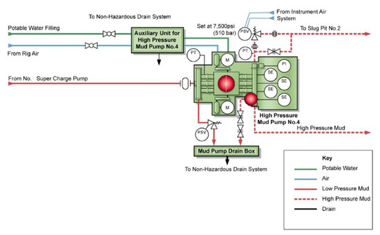
Whether onshore or offshore, well drilling sites rely on a multitude of systems to successfully perform the drilling operation. The mud pump is a key component tasked with circulating drilling fluid under high pressure downhole. The mud pump can be divided into two key sections: the power end or crosshead and the fluid end. Proper alignment of the pump’s crosshead to the fluid end liner is necessary to maximizing piston and liner life. Misalignment contributes to
accelerated wear on both the piston and the liner, and replacing these components requires downtime of the pump. Traditional methods of inspecting alignment range from using uncalibrated wooden rods, Faro Arms and micrometers to check the vertical and horizontal alignment of the piston rod OD to the piston liner ID. These are time consuming and cumbersome techniques that are ultimately not well suited to troubleshoot and solve alignment issues.
A “Mud Pump Laser Alignment Kit” enables you to measure where the piston will run through the liner at various positions along the pump’s stroke. It will also project a laser centerline from the fluid end back towards the rear power end of the pump that can be used to determine how much shimming is required to correct any alignment issues. The kit can include either a 2-Axis receiver or a 4-Axis which accepts the laser beam and documents where it falls on the active surface of the receiver. The 4-Axis receiver can decrease alignment time by as much as 50% as it will measure angularity as well as X and Y while the 2-Axis does not and will need multiple measurement locations to get the same information. In addition, the alignment system is a non-intrusive service requiring the removal of only the piston rod which allows for much quicker service and less down time on the pump. As the mud pumps in question are located globally both on and offshore, having a small, portable system is another great advantage. Our recommendation would be Pinpoint laser System’s “Mud Pump Alignment Kit”. They are being used by many of the leading repair service companies and have been their main alignment tool for over 15 years. Manufacturers are also utilizing these for new pump set-up.

In our important role as hydraulic pump manufacturers, we are aware of the large number of variables that need to be considered when choosing the right pump for the specific application. The purpose of this first article is to begin to shed light on the large number of technical indicators within the hydraulic pump universe, starting with the parameter “pump head”.
The head of a pump is a physical quantity that expresses the pump’s ability to lift a given volume of fluid, usually expressed in meters of water column, to a higher level from the point where the pump is positioned. In a nutshell, we can also define head as the maximum lifting height that the pump is able to transmit to the pumped fluid. The clearest example is that of a vertical pipe rising directly from the delivery outlet. Fluid will be pumped down the pipe 5 meters from the discharge outlet by a pump with a head of 5 meters. The head of a pump is inversely correlated with the flow rate. The higher the flow rate of the pump, the lower the head.
What is the head of a pump? As mentioned earlier, the head corresponds to the actual energy that the pump delivers to the fluid. The Bernoulli equation is applied between the pump’s inlet and outlet sections:
However, during the design stage, P1 and P2 are never known (as there is no physical element yet and therefore it is not possible to effectively measure the pump’s inlet and outlet pressure).
Now we will examine a more complex issue, that is the calculation of the last term of the aforementioned equation, which represents the total of the losses distributed along the pipes (suction and delivery) and the concentrated losses (valves, curves, etc.).
At this point we can easily calculate the head losses of the system, and therefore choose the correct size of the pump to achieve the desired flow rate at the resulting equivalent head.
The pump head indicator is present and can be found in the data sheets of all our main products. To obtain more information on the technical data of our pumps, please contact the technical and sales team.
We provide hydraulic components & repair services for industrial applications like paper mills, saw mills, steel mills, recycling plants, oil & gas applications and mobile applications, including construction, utility, mining, agricultural and marine equipment. This includes hydraulic pumps, motors, valves, servo/prop valves, PTOs, cylinders & parts.

A properly serviced pulsation dampener is critical for your mud pumps’ efficiency, safety, and performance. Unfortunately, there aren’t many resources available to educate personnel on executing safe and effective servicing procedures. Please review the following steps with your personnel for safe pulsation dampener maintenance.

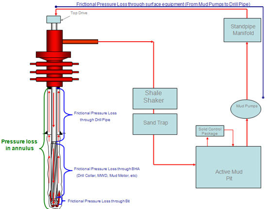
Engineers may have some basic ideas on how to optimize the design parameters of a circulation sub to achieve their goals. For example, increasing the total flow area of a circulation sub will increase the bypass flow rate, reduce pump pressure, etc. This case study will quantify the impacts of various circulation sub parameters and fluid properties on pump pressure and ECD for a wellbore cleanup operation. We used a wellbore cleanup hydraulics software to perform this case study. Numerical methods are employed to obtain the correct flow split percentage at the location of the circulation sub. The flow split is obtained such that the summation of the frictional pressure losses inside the pipe below the circulation sub and in the annulus below the circulation sub should be equal to the pressure loss through the circulation sub nozzles.
Figure 2 shows the wellbore configuration used for the example calculation. This is the basic case, from which we will perform sensitivity studies on each of 5 parameters. Note that the flow rate is left blank because it is run at several values for all stages.
The flow split at a circulation sub is determined as the fluid chooses the path of least resistance. The rates of flow through the circulation sub and down the string are determined when these two flow paths reach a pressure balanced state. When fluid inside pipe travels to the circulation sub, it faces 2 choices. The first one is to flow downward through the pipe and up the annulus. Let us call this Flow Path A. The alternative path is sideways through the circulation sub’s nozzles. We will call this Flow Path B.
The frictional pressure loss, or flow resistance, along Path A is a function of fluid viscosity, density, flow rate, pipe ID, hole ID, pipe OD and flow path length. On the other hand, the resistance of Path B is dominated by the pressure drop across the nozzles, which is reversely proportional to the square of the TFA of those nozzles. As we increase the TFA of a circulation sub, it becomes much easier for fluid to flow through Path B. As a result, less fluid will flow through Path A and the frictional pressure losses in the lower pipe and annular sections will be reduced. Whatever the percentage of flow split, the pump pressure and ECD of the system are both reduced by the fluid bypass.
Accompanying these increased bypass ratios, both the pump pressure and bottom hole ECD reduce rapidly at beginning and more gradually later, as shown in Figure 5 and 6, respectively. The pump pressure is reduced by almost 80% when TFA is increased from 0 (in2) to 1 (in2) for a flow rate of 6 (bpm). Meanwhile, for the same flow rate, bottom hole ECD is reduced by 7.6%. Further increase of TFA from 1 (in2) to 2 (in2) yields only marginal reduction.
The location of the circulation sub affects the overall downhole hydraulics. A circulation sub establishes a communication path between fluid inside the pipe and fluid in the annulus. The closer a circulation sub is to surface, the greater the fluid bypass ratio is, because Flow Path A is getting longer and creates a higher frictional pressure drop. Figure 7 shows the bypass ratios at various circulation sub locations along the wellbore. As expected, if we place the circulation sub at the bottom of the pipe, it would have no effect on pump pressure or bottom hole ECD.
To take advantage of its unique characteristic for wellbore cleanup operations, a circulation sub is often placed at the depth where the wellbore geometry changes, such as the previous casing shoe. By increasing the pump rate, the hole section below the circulation sub with a smaller annular clearance can maintain the required fluid velocity from the downward split flow. The velocity of the fluid in the larger OD annulus above the circulation sub will see both the flow rate traveling down the string and through the sub’s ports, increasing the annular velocity to closely match that in the narrow clearance hole below.
Greater reductions in both the pump pressure requirement and bottom hole ECD are achieved when a circulation sub is placed closer to surface, as seen in Figures 8 and 9. The pressure and ECD drops because less fluid is traveling through the narrower clearance section of the annulus.


 8613371530291