
mud pump calculations brands

NOTE: Max RPM in the above equation varies according to type of pump, size of stroke, and other variables. Duplex pumps often run about 100 RPM Max. while triplex pumps will run somewhere between 100 RPM Max and 400 RPM Max.
I have a reciprocating pump and I know what my max rated rod load is (in foot pounds). I also know what size plunger size my pump has. What PSI will my pump produce?
Specific Gravity is used when sizing a centrifugal pump. Liquids with a specific gravity greater than 1.0 are heavier than water and conversely, liquids with a specific gravity lower than 1.0 are lighter weight than water and will generally float on water.

Continental Emsco Drilling Products, Inc., which consisted of Emsco drilling machinery and Wilson mobile rigs, was purchased by National-Oilwell, Inc on July 7, 1999. To our knowledge, no pumps have been manufactured and sold under the Emsco brand name since National-Oilwell acquired them.
Fairbanks Morse pumps are currently manufactured in Kansas City, Kansas. Fairbanks Morse is a division of Pentair ever since August, 1997 when Pentair purchased the General Signal Pump Group.
Gaso pumps are manufactured by National Oilwell Varco. Gaso was acquired as "Wheatley Gaso" by National-Oilwell in the year 2000. At the time, Wheatley Gaso was owned by Halliburton.
Skytop Brewster pumps are no longer available as new pumps. Skytop Brewster(Cnsld Gold), a unit of Hansen PLC"s Consolidated Gold Fields subsidiary, was acquired while in bankruptcy by National-Oilwell, Inc. in November, 1999.

The 2,200-hp mud pump for offshore applications is a single-acting reciprocating triplex mud pump designed for high fluid flow rates, even at low operating speeds, and with a long stroke design. These features reduce the number of load reversals in critical components and increase the life of fluid end parts.
The pump’s critical components are strategically placed to make maintenance and inspection far easier and safer. The two-piece, quick-release piston rod lets you remove the piston without disturbing the liner, minimizing downtime when you’re replacing fluid parts.

Rig pump output, normally in volume per stroke, of mud pumps on the rig is one of important figures that we really need to know because we will use pump out put figures to calculate many parameters such as bottom up strokes, wash out depth, tracking drilling fluid, etc. In this post, you will learn how to calculate pump out put for triplex pump and duplex pump in bothOilfield and Metric Unit.

Whether onshore or offshore, well drilling sites rely on a multitude of systems to successfully perform the drilling operation. The mud pump is a key component tasked with circulating drilling fluid under high pressure downhole. The mud pump can be divided into two key sections: the power end or crosshead and the fluid end. Proper alignment of the pump’s crosshead to the fluid end liner is necessary to maximizing piston and liner life. Misalignment contributes to
accelerated wear on both the piston and the liner, and replacing these components requires downtime of the pump. Traditional methods of inspecting alignment range from using uncalibrated wooden rods, Faro Arms and micrometers to check the vertical and horizontal alignment of the piston rod OD to the piston liner ID. These are time consuming and cumbersome techniques that are ultimately not well suited to troubleshoot and solve alignment issues.
A “Mud Pump Laser Alignment Kit” enables you to measure where the piston will run through the liner at various positions along the pump’s stroke. It will also project a laser centerline from the fluid end back towards the rear power end of the pump that can be used to determine how much shimming is required to correct any alignment issues. The kit can include either a 2-Axis receiver or a 4-Axis which accepts the laser beam and documents where it falls on the active surface of the receiver. The 4-Axis receiver can decrease alignment time by as much as 50% as it will measure angularity as well as X and Y while the 2-Axis does not and will need multiple measurement locations to get the same information. In addition, the alignment system is a non-intrusive service requiring the removal of only the piston rod which allows for much quicker service and less down time on the pump. As the mud pumps in question are located globally both on and offshore, having a small, portable system is another great advantage. Our recommendation would be Pinpoint laser System’s “Mud Pump Alignment Kit”. They are being used by many of the leading repair service companies and have been their main alignment tool for over 15 years. Manufacturers are also utilizing these for new pump set-up.

Having a quality mud pump is a critical part of keeping your oil well drilling system running as smoothly as possible. Dragon carries a wide range of mud pumps for systems of all kinds and jobs of all sizes. We also carry a 50 BPM mud mixing table to make drilling fluid mixing more efficient and accurate so you can always get the job done safely and correctly. View our full well service pump and mud pump selection to find the right system for your job site, or check out the rest of our drilling rigs for even more options.

When choosing a size and type of mud pump for your drilling project, there are several factors to consider. These would include not only cost and size of pump that best fits your drilling rig, but also the diameter, depth and hole conditions you are drilling through. I know that this sounds like a lot to consider, but if you are set up the right way before the job starts, you will thank me later.
Recommended practice is to maintain a minimum of 100 to 150 feet per minute of uphole velocity for drill cuttings. Larger diameter wells for irrigation, agriculture or municipalities may violate this rule, because it may not be economically feasible to pump this much mud for the job. Uphole velocity is determined by the flow rate of the mud system, diameter of the borehole and the diameter of the drill pipe. There are many tools, including handbooks, rule of thumb, slide rule calculators and now apps on your handheld device, to calculate velocity. It is always good to remember the time it takes to get the cuttings off the bottom of the well. If you are drilling at 200 feet, then a 100-foot-per-minute velocity means that it would take two minutes to get the cuttings out of the hole. This is always a good reminder of what you are drilling through and how long ago it was that you drilled it. Ground conditions and rock formations are ever changing as you go deeper. Wouldn’t it be nice if they all remained the same?
Centrifugal-style mud pumps are very popular in our industry due to their size and weight, as well as flow rate capacity for an affordable price. There are many models and brands out there, and most of them are very good value. How does a centrifugal mud pump work? The rotation of the impeller accelerates the fluid into the volute or diffuser chamber. The added energy from the acceleration increases the velocity and pressure of the fluid. These pumps are known to be very inefficient. This means that it takes more energy to increase the flow and pressure of the fluid when compared to a piston-style pump. However, you have a significant advantage in flow rates from a centrifugal pump versus a piston pump. If you are drilling deeper wells with heavier cuttings, you will be forced at some point to use a piston-style mud pump. They have much higher efficiencies in transferring the input energy into flow and pressure, therefore resulting in much higher pressure capabilities.
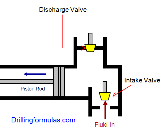
Piston-style mud pumps utilize a piston or plunger that travels back and forth in a chamber known as a cylinder. These pumps are also called “positive displacement” pumps because they literally push the fluid forward. This fluid builds up pressure and forces a spring-loaded valve to open and allow the fluid to escape into the discharge piping of the pump and then down the borehole. Since the expansion process is much smaller (almost insignificant) compared to a centrifugal pump, there is much lower energy loss. Plunger-style pumps can develop upwards of 15,000 psi for well treatments and hydraulic fracturing. Centrifugal pumps, in comparison, usually operate below 300 psi. If you are comparing most drilling pumps, centrifugal pumps operate from 60 to 125 psi and piston pumps operate around 150 to 300 psi. There are many exceptions and special applications for drilling, but these numbers should cover 80 percent of all equipment operating out there.
The restriction of putting a piston-style mud pump onto drilling rigs has always been the physical size and weight to provide adequate flow and pressure to your drilling fluid. Because of this, the industry needed a new solution to this age-old issue.
As the senior design engineer for Ingersoll-Rand’s Deephole Drilling Business Unit, I had the distinct pleasure of working with him and incorporating his Centerline Mud Pump into our drilling rig platforms.
In the late ’90s — and perhaps even earlier — Ingersoll-Rand had tried several times to develop a hydraulic-driven mud pump that would last an acceptable life- and duty-cycle for a well drilling contractor. With all of our resources and design wisdom, we were unable to solve this problem. Not only did Miller provide a solution, thus saving the size and weight of a typical gear-driven mud pump, he also provided a new offering — a mono-cylinder mud pump. This double-acting piston pump provided as much mud flow and pressure as a standard 5 X 6 duplex pump with incredible size and weight savings.
The true innovation was providing the well driller a solution for their mud pump requirements that was the right size and weight to integrate into both existing and new drilling rigs. Regardless of drill rig manufacturer and hydraulic system design, Centerline has provided a mud pump integration on hundreds of customer’s drilling rigs. Both mono-cylinder and duplex-cylinder pumps can fit nicely on the deck, across the frame or even be configured for under-deck mounting. This would not be possible with conventional mud pump designs.
The second generation design for the Centerline Mud Pump is expected later this year, and I believe it will be a true game changer for this industry. It also will open up the application to many other industries that require a heavier-duty cycle for a piston pump application.

Pumps tend to be one of the biggest energy consumers in industrial operations. Pump motors, specifically, require a lot of energy. For instance, a 2500 HP triplex pump used for frac jobs can consume almost 2000 kW of power, meaning a full day of fracking can cost several thousand dollars in energy costs alone!
So, naturally, operators should want to maximize energy efficiency to get the most for their money. Even a 1% improvement in efficiency can decrease annual pumping costs by tens of thousands of dollars. The payoff is worth the effort. And if you want to remotely control your pumps, you want to keep efficiency in mind.
In this post, we’ll point you in the right direction and discuss all things related to pump efficiency. We’ll conclude with several tips for how you can maintain pumping efficiency and keep your energy costs down as much as possible.
In simple terms, pump efficiency refers to the ratio of power out to power in. It’s the mechanical power input at the pump shaft, measured in horsepower (HP), compared to the hydraulic power of the liquid output, also measured in HP. For instance, if a pump requires 1000 HP to operate and produces 800 HP of hydraulic power, it would have an efficiency of 80%.
Remember: pumps have to be driven by something, i.e., an electric or diesel motor. True pump system efficiency needs to factor in the efficiency of both the motor AND the pump.
Consequently, we need to think about how electrical power (when using electric motors) or heat power (when using combustion engines) converts into liquid power to really understand pump efficiency.
Good pump efficiency depends, of course, on pump type and size. High-quality pumps that are well-maintained can achieve efficiencies of 90% or higher, while smaller pumps tend to be less efficient. In general, if you take good care of your pumps, you should be able to achieve 70-90% pump efficiency.
Now that we have a better understanding of the pump efficiency metric, let’s talk about how to calculate it. The mechanical power of the pump, or the input power, is a property of the pump itself and will be documented during the pump setup. The output power, or hydraulic power, is calculated as the liquid flow rate multiplied by the "total head" of the system.
IMPORTANT: to calculate true head, you also need to factor in the work the pump does to move fluid from the source. For example, if the source water is below the pump, you need to account for the extra work the pump puts in to draw source water upwards.
*Note - this calculation assumes the pump inlet is not pressurized and that friction losses are minimal. If the pump experiences a non-zero suction pressure, or if there is significant friction caused by the distance or material of the pipe, these should be factored in as well.
You"ll notice that the elevation head is minimal compared to the discharge pressure, and has minimal effect on the efficiency of the pump. As the elevation change increases or the discharge pressure decreases, however, elevation change will have a greater impact on total head.
Obviously, that’s a fair amount of math to get at the pump efficiency, considering all of the units conversions that need to be done. To avoid doing these calculations manually, feel free to use our simple pump efficiency calculator.
Our calculations use static variables (pump-rated horsepower and water source elevation) and dynamic variables (discharge flow and pressure). To determine pump efficiency, we need to measure the static variables only once, unless they change.
If you want to measure the true efficiency of your pump, taking energy consumption into account, you could add an electrical meter. Your meter should consist of a current transducer and voltage monitor (if using DC) for electrical motors or a fuel gauge for combustion. This would give you a true understanding of how pump efficiency affects energy consumption, and ultimately your bank account.
Up until this point, we’ve covered the ins and outs of how to determine pump efficiency. We’re now ready for the exciting stuff - how to improve pump efficiency!
One of the easiest ways to improve pump efficiency is to actually monitor pumps for signs of efficiency loss! If you monitor flow rate and discharge (output power) along with motor current or fuel consumption, you’ll notice efficiency losses as soon as they occur. Simply having pump efficiency information on hand empowers you to take action.
Another way to increase efficiency is to keep pumps well-maintained. Efficiency losses mostly come from mechanical defects in pumps, e.g., friction, leakages, and component failures. You can mitigate these issues through regular maintenance that keeps parts in working order and reveals impending failures. Of course, if you are continuously monitoring your pumps for efficiency drops, you’ll know exactly when maintenance is due.
You can also improve pump efficiency by keeping pumps lubricated at all times. Lubrication is the enemy of friction, which is the enemy of efficiency (“the enemy of my enemy is my friend…”).
A fourth way to enhance pump efficiency is to ensure your pumps and piping are sized properly for your infrastructure. Although we’re bringing this up last, it’s really the first step in any pumping operation. If your pumps and piping don’t match, no amount of lubricant or maintenance will help.
In this post, we’ve given you the full rundown when it comes to calculating and improving pump efficiency. You can now calculate, measure, and improve pump efficiency, potentially saving your business thousands of dollars annually on energy costs.
For those just getting started with pump optimization, we offer purpose-built, prepackaged solutions that will have you monitoring pump efficiency in minutes, even in hazardous environments.

In our important role as hydraulic pump manufacturers, we are aware of the large number of variables that need to be considered when choosing the right pump for the specific application. The purpose of this first article is to begin to shed light on the large number of technical indicators within the hydraulic pump universe, starting with the parameter “pump head”.
The head of a pump is a physical quantity that expresses the pump’s ability to lift a given volume of fluid, usually expressed in meters of water column, to a higher level from the point where the pump is positioned. In a nutshell, we can also define head as the maximum lifting height that the pump is able to transmit to the pumped fluid. The clearest example is that of a vertical pipe rising directly from the delivery outlet. Fluid will be pumped down the pipe 5 meters from the discharge outlet by a pump with a head of 5 meters. The head of a pump is inversely correlated with the flow rate. The higher the flow rate of the pump, the lower the head.
What is the head of a pump? As mentioned earlier, the head corresponds to the actual energy that the pump delivers to the fluid. The Bernoulli equation is applied between the pump’s inlet and outlet sections:
However, during the design stage, P1 and P2 are never known (as there is no physical element yet and therefore it is not possible to effectively measure the pump’s inlet and outlet pressure).
At this point we can easily calculate the head losses of the system, and therefore choose the correct size of the pump to achieve the desired flow rate at the resulting equivalent head.
The pump head indicator is present and can be found in the data sheets of all our main products. To obtain more information on the technical data of our pumps, please contact the technical and sales team.
Many things go into getting the most life out of your mud pump and its components — all important to extend the usage of this vital piece of equipment on an HDD jobsite. Some of the most important key points are covered below.
The most important thing you can do is service your pump, per the manufacturer’s requirements. We get plenty of pumps in the shop for service work that look like they have been abused for years without having basic maintenance, such as regular oil changes. You wouldn’t dream of treating your personal vehicle like that, so why would you treat your pump like that.
Check the oil daily and change the oil regularly. If you find water or drilling mud contamination in the oil, change the oil as soon as possible. Failure to do so will most likely leave you a substantial bill to rebuild the gear end, which could have been avoided if proper maintenance procedures would have been followed. Water in the oil does not allow the oil to perform correctly, which will burn up your gear end. Drilling mud in your gear end will act as a lapping compound and will wear out all of the bearing surfaces in your pump. Either way it will be costly. The main reasons for having water or drilling mud in the gear end of your pump is because your pony rod packing is failing and/or you have let your liners and pistons get severely worn. Indication of this is fluid that should be contained inside the fluid end of your pump is now moving past your piston and spraying into the cradle of the pump, which forces its way past the pony rod packing. Pony rod packing is meant to keep the oil in the gear end and the liner wash fluid out of the gear end. Even with brand new packing, you can have water or drilling fluid enter the gear end if it is sprayed with sufficient force, because a piston or liner is worn out.
There is also usually a valve on the inlet of the spray bar. This valve should be closed enough so that liner wash fluid does not spray all over the top of the pump and other components.
Liner wash fluid can be comprised of different fluids, but we recommend just using clean water. In extremely cold conditions, you can use RV antifreeze. The liner wash or rod wash system is usually a closed loop type of system, consisting of a tank, a small pump and a spray bar. The pump will move fluid from the tank through the spray bar, and onto the inside of the liner to cool the liner, preventing scorching. The fluid will then collect in the bottom of the cradle of the pump and drain back down into the collection tank below the cradle and repeat the cycle. It is important to have clean fluid no matter what fluid you use. If your liners are leaking and the tank is full of drilling fluid, you will not cool the liners properly — which will just make the situation worse. There is also usually a valve on the inlet of the spray bar. This valve should be closed enough so that liner wash fluid does not spray all over the top of the pump and other components. Ensure that the water is spraying inside the liner and that any overspray is not traveling out of the pump onto the ground or onto the pony rod packing where it could be pulled into the gear end. If the fluid is spraying out of the cradle area and falling onto the ground, it won’t be long before your liner wash tank is empty. It only takes a minute without the cooling fluid being sprayed before the liners become scorched. You will then need to replace the pistons and liners, which is an avoidable costly repair. Make a point to check the liner wash fluid level several times a day.
Drilling fluid — whether pumping drilling mud, straight water or some combination of fluid — needs to be clean. Clean meaning free of solids. If you are recycling your fluid, make sure you are using a quality mud recycling system and check the solids content often throughout the day to make sure the system is doing its job. A quality mud system being run correctly should be able to keep your solids content down to one quarter of 1 percent or lower. When filling your mud recycling system, be sure to screen the fluid coming into the tanks. If it is a mud recycling system, simply make sure the fluid is going over the scalping shaker with screens in the shaker. If using some other type of tank, use an inline filter or some other method of filtering. Pumping out of creeks, rivers, lakes and ponds can introduce plenty of solids into your tanks if you are not filtering this fluid. When obtaining water out of a fire hydrant, there can be a lot of sand in the line, so don’t assume it’s clean and ensure it’s filtered before use.
Cavitation is a whole other detailed discussion, but all triplex pumps have a minimum amount of suction pressure that is required to run properly. Make sure this suction pressure is maintained at all times or your pump may cavitate. If you run a pump that is cavitating, it will shorten the life of all fluid end expendables and, in severe cases, can lead to gear end and fluid end destruction. If the pump is experiencing cavitation issues, the problem must be identified and corrected immediately.
The long and the short of it is to use clean drilling fluid and you will extend the life of your pumps expendables and downhole tooling, and keep up with your maintenance on the gear end of your pump. Avoid pump cavitation at all times. Taking a few minutes a day to inspect and maintain your pump can save you downtime and costly repair bills.


 8613371530291