
mud pump pulsation dampener precharge free sample

At Sigma Drilling Technologies, we utilize out-of-the-box thinking and cutting edge innovation. From our revolutionary pulsation control systems, to our one of a kind performance boosting solutions, Sigma delivers unsurpassed technology. Helping businesses succeed by getting the most out their equipment investment is our goal. Let us partner with your team to help maximize your production output, enhance equipment investment, and place you at the forefront of industry advancements.

The Charge Free Dampening System™ combines the advanced technologies of Sigma’s Charge Free Dampeners™, Sigma’s Charge Free Conversion Kits®, Sigma’s Charge Free Stabilizer™, and Sigma’s Acoustic Assassin® to create the best available pulsation control solution. When it comes to performance and cost, Sigma’s Charge Free Dampening System™ will out perform more expensive dampeners while significantly reducing weight, size, and cost.
The Charge Free Dampener™ was designed to maximize the superior performance of Sigma’s Discharge Charge Free Conversion Kit®. The Charge Free Dampener™ was built from the ground up with performance, safety, and longevity in mind, for every aspect.
The Charge Free Stabilizer™ was designed to be installed directly before the suction manifold port between the mud pump and the charge pump. Maximizing mud pump performance by eliminating cavitation while isolating both the mud and charge pumps.
The Acoustic Assassin® was designed to be installed between the pump loop manifold and the production line. This fixture is a multi-chambered baffling system that will reduce damaging acoustic resonance generated by reciprocating pumps. The Acoustic Assassin® is an ideal addition to any pulsation control system.
The Charge Free Conversion Kit® is a high performance pulsation control kit that utilizes both compression and kinetic exchange for superior performance over traditional pulsation control methods of the past. With a gigantic increase in surface area, compression tuning, and a design to maximize energy exchange, the CFC Kits control pulsations from the pump while cleaning the signal for MWD tools.

A Pulsation Dampener is an inline dampening device used to smooth out pulsations in a pump’s output. They are used alongside a pump as a mounted accessory to help achieve certain flow rates for an application. They can be used with a variety of Positive Displacement Pumps which typically generate a pulsed flow (Diaphragm Pumps, Peristaltic Pumps, Dosing Pumps, Piston Pumps etc)
Pulsation Dampeners are required in some process applications when the customer needs smooth flow into the next phase of the production line, for example, to get an accurate reading through a flow meter or to fill a hopper consistently. On the flip side, Dampeners can be used to reduce water hammer effects through pipework. Water hammer is where the pump causes the pipes to vibrate and potentially fail, a smooth flow from a Pulsation Dampener reduces this.
For example, Diaphragm Pumps inherently produce a very turbulent discharge flow meaning that in some instances a Pulsation Dampeners are required to give a smooth pulse-free flow.
In the Tapflo UK range, we focus on Pulsation Dampeners for Diaphragm and Peristaltic Pumps, although we can also supply them for other pump technologies.
The Active Pulsation Dampener works by supplying an equal pressure to the pulsation supplied by the pump. The Dampener supplies this pressure during the low-pressure points of the pump’s operation, as the pressure drops between pump strokes creating a pulsating flow. The pressure supplied by the dampener decreases pressure variations, therefore producing a steady flow from your Diaphragm Pump. You can see the pressure drops and Pulsation Dampener benefits in action in the diagram below.
Tapflo supplied a 2” Air Operated Diaphragm Pump to a bleach factory, the customer used the T400 PTT for a couple of days and then called us to explain that the bleach line, running along the roof of his production facility, was shaking. Due to the nature of the product being pumped health and safety on site could not allow this to continue.
To support our Peristaltic Pump customers, Tapflo offers an in-line Pulsation Dampener for our PT and PTL Series’. They can reduce the pulsation of your PT Pump by as much as 90% to reduce the vibration and water hammer effects on pipework. Another benefit of this accessory is its ability to be installed on-site horizontally or vertically for flexible installation.
Our custom-designed systems will absorb excess energy pulsing through the pump and piping system by creating a low-pressure area to dampen the excess shocks and vibrations. Because a pulsation dampener regulates the release of energy, your system will be better protected and run more smoothly. After installing a pulsation dampener, customers notice that their system:

Such pressure pulsations may result in the discharge of a positive displacement pump while pressure surges may result in the closing of a fast-acting valve in a flowing stream of fluid. By eliminating the cyclic pulsation in a fluid the associated meters, valves, fittings and the pumps themselves have their service life increased as well as greatly improving the accuracy of meter readings of fluid conditions. Surge absorbers control any sudden pressure surges that may be caused by a pump start up or shutdown and also reduces to a negligible value any surges in pipelines that may result from power failure or other causes. The surge absorbers are also indispensible to truck and tank car loading operations and for protecting airport fuel and hydrant systems.
Such pulsation dampeners or surge absorbers have usually comprised a pressure vessel or accumulator having a flexible diaphragm or bladder disposed within a cavity of the pressure vessel. A compressible fluid is precharged on one side of the diaphragm while the other side of the diaphragm is exposed to the fluid having the pressure pulsation or surges to be dampened.
While there is clear difference in application of the pulsation dampener and the surge absorber, the same apparatus, in fact, will serve both applications and a reference to one application herein will be understood to include the other application unless expressly excluded herein.
The art of dampening the pressure surges or pulsations in a stream of incompressible fluid has risen to a high level of skill. Examples of the technology of this art are reflected in the following patents that are assigned to the assignee of the present invention:______________________________________
While the embodiment disclosed in Knox U.S. Pat. No. 2,757,689 has been extremely successful, it did possess certain limitations. In order to be effective for the full range of pulsating fluid conditions, the pulsation dampener is precharged with a compressible fluid, usually nitrogen, to a preselected optimum pressure. If the preselected pressure exceeds the pulsating fluid pressure no dampening will occur. While the preselected optimum pressure may be changed as operating conditions of the pulsating fluid changes, such changes in the preselected pressure were time consuming to make. To assure the proper volume of the compressible fluid at the preselected optimum pressure in the pulsation dampener, it was desirable to reduce the pulsating fluid pressure to zero. As pulsating fluid operating pressure increased, it was necessary to increase the preselected optimum pressure and which increased the period of time to pressure the pulsating fluid sufficiently for pulsation dampening to occur. This is very undesirable and particularly so in the case of positive displacement drilling mud pumps used during rotary drilling operations. During such drilling operations pressure surges or pulses from another source are often used as signals and the presence of undesired pulsations may be incorrectly interpreted as a signal.
To achieve a large range of operating conditions, a relatively large volume of compressible fluid was required. At higher operating pressure of the pulsating fluid, the weight of the pulsation dampener increased significantly for a given volume of compressible fluid. Not only did this make the initial cost of the pulsation dampener greater, but also the cost of transporting the pulsation dampener. This latter cost could be very significant in rotary drilling operations where the pulsation dampener is transported between drilling sites. U.S. Pat. Nos. 2,804,884 and 3,169,551 are similar in construction to the previously discussed Knox patent and generally have the same characteristics.
In U.S. Pat No. 2,773,455, issued Dec. 11, 1956 to Mercier, an accumulator system using a pair of connected pulsation dampeners is disclosed. The pulsation dampeners are arranged to provide a differential pressure, or hydrostatic head therebetween of the pulsating fluid. The resulting greater dampening pressure in the lower accumulator is communicated to the upper accumulator for insuring that dampening fluid pressure in the upper accumulator exceeds the pulsating fluid pressure. While such arrangement was useful, both diaphragms were exposed to the full operating pressure at all operating pressure levels which would reduce diaphragm life. Furthermore, the volume of pulse absorbing gases uniformly decreased at high operating pressure which reduced the overall system efficiency to that of a single accumulator.
An improved pulsation dampener or surge absorber providing dampening at relatively low operating pressure which maintains high volumetric dampening efficiency at the higher operating pressures without having to increase pressure of the dampening fluid. A third dampening zone having compressible dampening fluid therein is operably connected with the normal compressible fluid dampening zone of the pulsation dampener. The third dampening zone is charged to a higher pressure than the normal dampening zone. Only when the operating fluid pressure exceeds the charged fluid pressure in the third zone does the third zone participate in the pulsation dampening. The additional volume of the third zone at the high pressure improves the dampening efficiency and capacity of the pulsation dampener.
The use of the third dampening zone enables a much smaller pulsation dampener to be provided in comparison with a pulsation dampener having only a normal dampening zone. This provides a savings both in initial cost as less material is needed to form the capacity of the pulsation dampener and increases the portability of the pulsation dampener.
The first embodiment of the pulsation dampener or surge absorber apparatus, generally designated A, is illustrated in FIG. 1. The apparatus A includes a pressure vessel generally designated PV formed by the primary pressure vessel 10 and the supplemental pressure vessel 12 having the top closing flange 14. Both the primary pressure vessel 10 and secondary pressure vessel 12 are substantially spherical in shape and are generally of steel construction such as those identified in the patents previously identified as being assigned to the assignee of the present invention and which are hereby fully incorporated by this reference. Both the primary pressure vessel 10 and the secondary pressure vessel 12 are formed by suitable means such as welding and which construction is well known to those skilled in the art.
Disposed within the cavity 16 adjacent the surface 10a is a first flexible diaphragm 22 for dividing the cavity 16 into a first zone below the diaphragm 22 and a second zone above the diaphragm 22. Fluid pressure in the first zone urges on the surface 22a of the diaphragm for urging a collapse of the diaphragm 22 while fluid pressure in the second zone urges on the surface 22b of the diaphragm for urging the diaphragm outwardly to the position illustrated where it is supported by the inner surface 10a of the pressure vessel 10. A suitable bridging insert or element (not illustrated) bridges over the inlet opening 18a to prevent an undesired pressure differential from extruding or flowing the diaphragm 22 when the pressure in the second zone exceeds the pressure in the first zone. The first zone communicates through the inlet opening 18a for urging on the diaphragm surface 22a with the pressure of the fluid having the pulsations to be dampened. The diaphragm 22 is provided with the annular collar 22c which is captured in an annular recess 10 c of the pressure vessel 10 for securing in the usual manner.
The above arrangement has been found to be of superior capacity in dampening fluid pressures over a wide spread range of operating pressure. Until the pressure of the operating fluid having the pulsation to be dampened exceeds the reference or charge pressure in a pulsation dampener, no dampening can occur. Thus it is desirable to have this pressure as low as possible. However, if this is done, the volume of the compressible fluid is usually so small at higher pressures that the volumetric efficiency becomes quite low. The larger the gas volume in the apparatus A the smaller will be the change in pressure with a given volume of fluid injected into the dampener by increased pressure of the operating fluid.
In order to increase efficiency at high pressure and maintain a low starting precharge pressure the above system has been provided. The primary dampener 10 is provided with a twenty gallon, or 75.7 liter, internal capacity with the secondary pressure vessel 12 being provided with a five gallon, or 18.9 liter, internal capacity. If a twenty gallon or 75.70 liter unit is precharged to 765 psia or 52.04 atmospheres with compressible fluid such as nitrogen gas, the volume would be compressed to 3.05 gallons or 11.54 liters at 5015 psia or 341.15 atmospheres pressure of the pulsating operating fluid. The change in pressure per gallon of operating fluid injected at 5015 psia or 341.15 atmospheres would be 1558 psia or 105.98 atmospheres. By precharging the five gallon or 18.92 liter secondary pressure vessel 12 to 2958 psia or 201.22 atmospheres an additional five gallons or 18.92 liters of gas volume would be added when that pressure is reached and the total gas volume available for dampening in both the primary pressure vessel 10 and the secondary pressure vessel 12 at an operating fluid pressure of 5015 psia or 341.15 atmospheres will be six gallons or 22.71 liters. The change in pressure of the compressible fluid per gallon injected would be lowered from 1558 psia or 105.99 atmospheres to 716 psia or 48.71 atmospheres. Such calculations are based upon isothermal compression and expansion. However, it is understood that when the gas is first compressed the conditions will be adiabatic and the compressed volume will be larger than that given above.
If the second zone is precharged to 765 psia or 52.04 atmospheres and the third zone to 2015 psia or 137.07 atmospheres slightly better dampening would occur at pressure of the operating fluid from 2015 psia or 137.07 atmospheres to 2958 psia or 201.22 atmospheres. However, beyond the 2958 psia or 201.22 atmospheres operating pressure a 2958 psia or 201.22 atmospheres precharge in the third zone would be preferred. Furthermore, at 5015 psia or 341.15 atmospheres the second zone would become inoperative as the lower diaphragm 22 would no longer displace any gas volume.
That condition could be avoided by increasing the precharge in the second zone, for example, to 1000 psia or 68.03 atmospheres and the precharge on the third zone to 2015 psia or 137.07 atmoshperes. Under those precharge pressure conditions, the final total gas volume will be six gallons or 22.71 liters at the 5015 psia or 341.15 atmospheres operating pressure. This would insure gas displacement in the second zone. However, the primary precharge 1000 psia or 68.03 atmospheres is higher than desirable for good diaphragm life of the diaphragm 22. To achieve the foregoing dampening over the 5000 pressure range with a single pressure vessel and diaphragm, it is necessary to use a forty gallon or 151.40 liter capacity pressure vessel. Such pressure vessel is both bulkier and heavier and submits the single diaphragm thereof to the full pressure differential range. Another advantage of the present tandem design is that an existing 20 gallon or 75.7 liter capacity pressure vessel 10 can be modified by replacing the flange thereof with the secondary pressure vessel 12 for increasing the capacity without the need to discard the existing pressure vessel 10.
In a second embodiment of the present invention A, illustrated in FIG. 2 and described in detail hereinafter, a pressure separator is provided by an adjustable spring loaded valve that is set to close when the dampening fluid pressure in the second zone is below a predetermined value and thereby isolating the high pressure in the third zone while the balance of the dampening gas in the second zone urging upon the diaphragm is allowed to expand to a much lower precharge value. This valve can be adjusted from time to time to close at a value suitable for the operating conditions. The valve thus serves to communicate the second and third zone at the upper pressure operating ranges and blocks communication therebetween for allowing the dampening pressure to be reduced in the second zone.
Disposed within the cavity 44 adjacent the surface 40a is a flexible diaphragm 52 for dividing the cavity 44 into a first zone below the diaphragm 52 and a second zone above the diaphragm 52. Fluid pressure in the first zone urges on the outer surface 52a of the diaphragm 52 for urging a collapse of the diaphragm 52 while fluid pressure in the second zone urges on the inner surface 52b of the diaphragm 52 for urging the diaphragm outwardly to a position where it would be supported by the inner surface 40a of the pressure vessel 40. A suitable bridging insert or element (not illustrated) will bridge over the inlet opening 46a to prevent an undesired pressure differential from extruding or flowing the diaphragm 52 when the pressure in the second zone exceeds the pressure in the first zone. The first zone communicates through the inlet opening 46a for urging on the diaphragm surface 52a with the pressure of the fluid having pulsations to be dampened. The diaphragm is provided with an annular collar 52c which is captured in an annular recess 40c of the primary pressure vessel 40 for securing and sealing in the usual manner.
The following procedure is used to precharge the tandem pulsation dampener of the second embodiment. First, the pressure control is released by turning the hand wheel 76 to release the urging of the spring 84. A pressure source such as a bottle of compressed nitrogen (not illustrated) is then connected to the charging valve 110 which communicates with the cavity 44 through a charging passage 68e in the usual manner. As the pressure of the nitrogen within the supplemental pressure vessel 42 increases it will urge upwardly upon the pressure plate 92 for urging it upwardly along with the magnetic assembly 90 which will carry the ball 82 upwardly from the seat 80. This will enable the charging pressure to flow from the third zone into the second zone where it will urge upon the surface 52b of the diaphragm 52. At a desired precharged level, for example, 1204 psia or 81.9 atmospheres, the pressure charge is terminated. The pressure adjustment hand wheel 76 is then turned to effect closure of the ball 82 upon the seat 80 and the opening pressure is set by further adjustment of the handle 76, for example, a pressure setting of 3015 psia or 205.1 atmospheres. Hydraulic pressure is then applied to the first zone to a level slightly greater than 3015 psia, for example, 3515 psia or 239.1 atmospheres, which will cause the valve 80 to open and the nitrogen pressure in the second and third chambers to equalize. When the hydraulic fluid pressure in the first zone is then reduced the valve will close at the 3015 psia or 205.1 atmospheres setting trapping that pressure in the upper or third zone while complete reduction of the hydraulic pressure in the first zone will expand the gas remaining in the secondary zone to 750 psia or 51 atmospheres. The pulsation dampener of FIG. 2 will then function in the same manner and with the same advantages as described with respect to the first embodiment.

A pulsation dampener reduces or eliminates the variations in pressure and flow produced by reciprocating pumps. In many applications, low frequency pressure waves cause problems within a given piping system and/or process. Eccentric, cam-driven pumps are probably the most commonly applied for services that require pulsation dampening, e.g., metering pumps and reciprocating (power) pumps.
Pulsation dampeners are found in a variety of designs, but for our purposes we will focus on only gas-charged pulsation dampeners, which rely on a calculated volume of compressed gas, usually Nitrogen, which is alternately compressed and expanded in synchronization with the pump plunger to reduce or eliminate pressure pulsations. This gas volume is normally separated from the process fluid by a flexible membrane. Common membrane designs include elastomeric bladders, PTFE diaphragms, PTFE bellows or stainless steel bellows.
Pressure waves or pulses are a consequence of the alternating acceleration and deceleration of fluid velocity corresponding to the travel of the piston or plunger. The pattern and amplitude of these pulses varies with pump configuration, specifically the number and size of pistons, as well as fluid compressibility factors.
It is precisely the fluid volume above mean on the discharge cycle of each stroke, which induces these pressure pulsations into a piping system. The number of pistons offered by the pump—given that all are of identical diameter and equally phased—displace a known peak volume above mean. These constants may be influenced by fluid compressibility, but for the purpose of this explanation we’ll assume none at this point. A pulsation dampener absorbs only that portion of piston displacement above mean flow, and then stores it momentarily before discharging it during the portion of the cycle below mean flow (on the suction stroke).
A simplex pump displaces a volume of fluid above mean that is equal to about 60 percent of total displacement. A duplex pump displaces a lower fluid volume above mean, approximately half that of a simplex pump. Pumps of three or more pistons of equal diameter, stroke length and proportionally phased will always present a very small fluid volume above mean to the piping system. A triplex pump, for example, produces about a 4 percent peak, as long as fluid compressibility factors and pump efficiencies are not at issue.
These smaller fluid volumes are accounted for by the crank angle of each of the cylinders. Triplex pumps are offset by 120-deg. Quadruplex pumps are set apart at 90-deg offsets; quintuplex pumps are offset 72-deg, and so on. It is the resulting overlap in pulses that yield the smaller fluid volumes above mean.
Fluid velocity gradients follow the same mechanical velocity gradients of the eccentric cam that drives the piston(s). Halfway through the piston’s forward travel (discharge stroke), fluid velocity between the discharge check valve and the pulsation dampener begins to decay. The corresponding drop in pressure causes the membrane inside the dampener to expand since the internal gas pre-charge pressure is now higher than the line pressure. The (stored) fluid now being displaced by the pulsation dampener maintains velocity downstream of the dampener thereby reducing, if not eliminating, any downstream pulsations.
Note: A pulsation dampener removes pulses only from the line downstream of the dampener—not upstream. That’s why it’s always recommended that discharge dampeners be installed as close to pump discharge nozzles as possible. In an application of a dampener for suction stabilization (reduction of acceleration head losses), it is the velocity gradient between the supply vessel and the suction nozzle that is minimized.
Let’s begin by defining the pump details required to properly size a pulsation dampener. We will use these values in a sample calculation to help clarify the process.
The result of the previous calculation is then divided by a constant. As noted previously, the constant is a function of pump configuration. We use a conservative 1.5 for simplex pumps, 2 for duplex pumps, and 7 for triplex pumps. Remember—if the fluid is compressible, then the constant may have to be adjusted downward.
Fluid volumes above mean are well within the range of these constants. The fluid pulse above mean flow from a simplex pump, for example, is about 60 percent. When we divide full stroke displacement by 1.5 the result is a conservative 67 percent. The divisor 7 that we use for triplex pumps allows for a nominal 14 percent fluid volume above mean. While 14 percent is far above the actual 4 percent produced by triplex pumps, the higher volume is an allowance for practical reasons, specifically size and nozzle limits. Otherwise, the result would be a very small dampener relative to pump size.
Ranges of (process) temperature and pressure must be considered in any sizing calculations for pulsation dampeners. Compensations must be made for temperature variations, which affect gas density, and dynamic variations in system pressure, since sizing is based on a set pre-charge pressure.
The objective is to select a dampener that is adequately sized to handle a range of operating pressures with a single pre-charge pressure. Remember that the gas pre-charge pressure should always be based on the minimum operating pressure as the pulsation dampener will have no effect when the system pressure is below the pre-charge pressure.
Changes in ambient temperature can also influence gas density, but they’re generally disregarded for the purposes of pulsation dampener sizing. It is usually sufficient to make seasonal adjustments to pre-charge pressures, if necessary. Temperature and pressure calculations are recommended to be done using absolute values (Kelvin for temperature and BarA or PSIA for pressure).
Some fluids are highly compressible, such as cryogenics, olefins, liquefied gases, anhydrous ammonia, etc. In these instances, the benefit of lower pulsations from multiple piston pumps may be somewhat compromised. Fluid compression occurs during the leading edge of the (eccentric) crank angle. Given sufficient pressure and a high enough compressibility factor, there may be little or no overlap of pulses at all—in which case, adjustments have to be made and pulsation dampeners with larger gas volumes should be selected.
By installing a properly-sized pulsation dampener, users can reduce or eliminate pipe shake, vibration and noise. The result is a continuous flow of product which is required in many metering, mixing and spraying applications. Reduced pressure pulsations minimize long-term damage to instrumentation and pump components while improving the accuracy of many flowmeters and increasing pump efficiency.
[0001] The present application relates generally to pulsation dampeners/dampners/dampers/ accumulators and, more specifically, to replacing the nitrogen within gas-charged pulsation dampeners with a reactive, compressible liquid while accounting for thermal expansion by one or more of augmenting with cellular material, a gap or less than full fill of the bladder with the reactive liquid, and a reset pressure relief valve.
[0002] In North America, the first commercial oil well entered operation in Oil Springs, Ontario in 1858, while the first offshore oil well was drilled in 1896 at the Summerland Oil Field on the California coast. Reciprocating systems, such as reciprocating pump systems and similar equipment, operate in many types of cyclic hydraulic applications. For example, reciprocating mud pump systems are used to circulate the mud or drilling fluid on a drilling rig.
[0003] As well depths and drilling efficiencies increased along came the need for highly efficient mud pumps. The early designs were rudimentary double acting duplex pumps that have since been replaced with high pressure and high horsepower single acting triplex and other single acting designs including quadruplex, quintuplex and hexuplex mud pumps.
[0004] Pressure peaks within the pumped fluid accelerate, with each pulsation, the deterioration of the pump, the pump’s fluid end expendable parts, and equipment downstream from the pump, such as measurement equipment used to determine drilling parameters, and wash pipe and wash pipe packing. Failure to control such pressure peaks inevitably affect the operating performance and operational life of the pump, pump fluid end expendable parts and all upstream or downstream components. Pressure peaks may also interfere with instrument signal detection, such that failure to control pressure peaks may also affect the signal detection and/or quality of the signal detection in (for example) measurement while drilling operations.
[0005] Thus, with increased pressure and pump horsepower came the need to reduce pulsations from the pump in order to maintain drilling efficiencies. In the early 1940’s, nitrogen gas charged pulsation dampeners were introduced beginning with 5, then 10 and now 20 gallon units. As drilling efficiencies are paramount, the need to have pulsation dampeners effectively reduce the level of pulsation energies and their potential interaction with system natural frequencies are becoming more critical. The interaction of the pump primary pulsation frequencies with those of the system sets up potentially harmful and destructive forces (vibrations) resulting in early fatigue failure of mud pump expendables, mud line equipment, Kelly and kicker hoses, top drive wash pipe packing and significant interference with managed pressure drilling (MPD), measurement while drilling (MWD), or logging while drilling (LWD) exploration and production activities.
[0006] Pulsation control equipment is typically placed immediately upstream or downstream from a reciprocating pump, often with a relative size and configuration proportional to the volume of desired fluid displacement per stroke of the pump and the maximum allotted magnitude of the pressure peaks that may be experienced by the pump system during each pulsation. Pulsation control equipment thus aids in reducing pump loads and minimizing pulsation amplitudes to the pump, the pump’s fluid end expendable parts and to equipment upstream or downstream. As a result, pulsation control equipment increases the relative operating performance and life of the pump, the pump’s fluid end expendable parts and any equipment upstream or downstream from the pump. In addition, drilling efficiency using MPD/MWD/LWD systems is impacted as discussed above.
[0007] Employing conventional gas charged dampener (or, equivalently for purposes of this disclosure, “dampener”, “damper,” “accumulator,” or “pulsation control equipment”) generally involves a pressure containment vessel in cylindrical, spherical, torospherical or similar shape in which resides a bladder (or, equivalently for purposes of this disclosure, “diaphragm” or “bellows”) that contains a nitrogen gas pre-charge. This conventional design has been adapted for use in drilling and all other industrial markets of positive displacement reciprocating piston/plunger pumps.
[0008] For gas-charged pulsation dampeners, the challenge has always been to establish the correct pre-charge on the bladder against expected system operating conditions. In steady- state operating conditions with established pre-charge, the system performance is acceptable. However, in contemporary MPD/MWD/LWD processes, where micro-process corrections are made continuously and system pressures fluctuating widely, the dampener performance and the service life of the bladder is reduced. As pre-charge on the dampener bladder can only be established against zero operating pressure, the system needs to be shut down such that productivity is curtailed when making changes to the dampener precharge. Once the calculated pre-charge is established, the bladder may fail when the system pressure varies outside the safe operating limits, or may fail to perform as desired when the system pressure varies outside the expected operating range.
[0010] In the absence of other solutions, a liquid-only, bladder-less (maintenance free) dampener has entered the market, but occupies a large space and/or has a large footprint since the performance (based purely on liquid compressibility) requires a large liquid volume to achieve acceptable pulsation control. The designs are more effective at higher system pressures and may achieve good pulsation control across all applications where system pressures fluctuate beyond what conventional pulsation dampeners are designed to handle, but the space trade-off needs to be considered.
[0011] A pulsation dampener includes a quantity of liquid reactive fluid (e.g., about 20 gallons) contained within a flexible diaphragm and separated from external pumped fluid flow by the flexible diaphragm. The liquid quantity of reactive fluid is selected to dampen pressure pulses within the external pumped fluid flow. The pulsation dampener is configured to accommodate thermal expansion of the quantity of liquid reactive fluid by one or more of including a quantity of compressible foam within the flexible diaphragm, allowing for a space between the flexible diaphragm when holding the quantity of the liquid reactive fluid and a body of the pulsation dampener, or providing a reset pressure relief valve [0012] Before undertaking the DETAILED DESCRIPTION below, it may be advantageous to set forth definitions of certain words and phrases used throughout this patent document: the terms “include” and “comprise,” as well as derivatives thereof, mean inclusion without limitation; the term “or,” is inclusive, meaning and/or; and the phrases “associated with” and “associated therewith,” as well as derivatives thereof, may mean to include, be included within, interconnect with, contain, be contained within, connect to or with, couple to or with, be communicable with, cooperate with, interleave, juxtapose, be proximate to, be bound to or with, have, have a property of, or the like. Definitions for certain words and phrases are provided throughout this patent document, those of ordinary skill in the art should understand that in many, if not most instances, such definitions apply to prior, as well as future uses of such defined words and phrases.
[0014] FIG. 1 is a plot of comparative estimated pulsation levels across a range of operating pressures within a mud pump system using various types of pulsation dampeners, including a pulsation dampener with a diaphragm filled or partially filled with reactive fluid according to various embodiments of the present disclosure;
[0015] FIG. 2 illustrates a diagrammatic view of a drilling system including a pulsation dampener with a diaphragm filled or partially filled with reactive fluid according to various embodiments of the present disclosure;
[0016] FIG. 3 illustrates a mud pump system pulsation dampener installation for which a diaphragm filled or partially filled with reactive fluid may be employed in accordance with embodiments of the present disclosure;
[0017] FIGS. 4A and 4B are cross-sectional diagrams illustrating a reactive fluid-filled pulsation dampener and its operation according to embodiments of the present disclosure; [0018] FIG. 5 depicts an embodiment of a piping network within which a hybrid reactive fluid dampener in accordance with embodiments of the present disclosure may be installed; [0019] FIG. 6 is a cross-sectional diagram illustrating a hybrid reactive fluid dampener in accordance with embodiments of the present disclosure;
[0020] FIGS. 7 A through 71 are various views illustrating a combination reactive fluid and compressive elastomer dampener in accordance with embodiments of the present disclosure; [0021] FIGS. 8 A through 8E illustrate a liquid reactive fluid dampener accommodating thermal expansion in accordance with embodiments of the present disclosure; and [0022] FIGS. 9A and FIG. 9B illustrate a liquid reactive fluid dampener relieving pressure from thermal expansion in accordance with embodiments of the present disclosure. DETAILED DESCRIPTION
[0023] FIGS. 1 through 9B, discussed below, and the various embodiments used to describe the principles of the present disclosure in this patent document are by way of illustration only and should not be construed in any way to limit the scope of the disclosure. Those skilled in the art will understand that the principles of the present disclosure may be also implemented in any suitably arranged standpipe manifold dampener or system dampener that can be used to control or partially control pulsation amplitudes as well as other types of gas charged pulsation control products
[0024] The present disclosure utilizes reactive, compressible fluid to replace the compressible gas medium in conventional pulsation dampeners. Suitable compressible fluids of the type contemplated in this application are known in the art.
[0025] The use of reactive fluid in pulsation control in accordance with the present disclosure is designed to limit pulsations to acceptable levels. FIG. 1 illustrates estimated pressure variations graphically for operation across the range of 0 to 7,500 pounds per square inch (psi). In typical drilling applications, following are the expected pulsation limits in pounds per square in gauge (psig) of the various systems that might be used within a system employing a typical, 5.5”xl2” single acting triplex mud pump:
[0026] As apparent from the table above and FIG. 1, the 20 gallon pulsation dampener using a “charge free” design (“PD20 CFC Kit,” using a compressible elastomer or elastomeric foam), offers relatively little pulsation control. The liquid only maintenance free dampener (“DR-130”), which is typically a 135 to 140 gallon spherical design, is superior and limits pulsation levels to as little as 100 psig, peak-to-peak, or less. However, as discussed above, the volume required for the liquid occupies a large space. The reactive fluid maintenance free system (“PD20 RFS PK-PK” offers very good pulsation control across the entire pump operating range. A smaller volume maintenance free discharge dampener can be combined with the reactive fluid-filled dampener as a hybrid design. In addition, while not addressed above, combining the use of a liquid only maintenance free dampener with reactive fluid filled or partially filled dampener allows for a much smaller overall footprint dampener that delivers excellent maintenance free pulsation control over the entire system/pump operating range.
[0027] The primary focus of the diaphragm filled or partially filled with reactive fluid (or, for most applications contemplated herein, a hybrid combination of liquids including reactive fluid that may be used interchangeably with reactive fluid liquid) within maintenance free pulsation dampeners is to ensure significant improvement on MPD drilling efficiencies and both MWD/LWD signal response as and when needed during drilling operations. The diaphragm filled or partially filled with reactive fluid essentially allows the driller to continue their mode of operation and gain higher drilling efficiencies in extended reach drilling programs without the need to precharge/recharge the conventional drilling dampener.
[0028] Compressible fluids of the type known in the art and contemplated herein typically have a thermal expansion that, when the fluid exposed to the higher temperatures of drilling muds or other fluids in other possible uses, will increase in volume. Accordingly, when the internal bladder volume is completely full, thermal expansion may cause a sufficient rise in internal bladder pressure to reduce the effectiveness of the pulsation energy mitigation and, possibly, result in an increase in pressure sufficient to burst the metal pressure vessel. Options for addressing this issue are described below.
[0029] FIG. 2 illustrates a diagrammatic view of a drilling system including a pulsation dampener for which a diaphragm filled or partially filled with reactive fluid or (a hybrid combination of liquids) may be employed according to various embodiments of the present disclosure. The embodiment of the drilling system 200 illustrated in FIG. 2 is for illustration only. FIG. 2 does not limit the scope of this disclosure to any particular implementation of a drilling or industrial pump system.
[0030] Referring now to FIG. 2, the drilling system 200 includes at least one mud pump 202 having a pulsation dampener (not separately depicted) mounted thereon and connected to the pump discharge line 204, and at least one mud pit 206. The drilling system 200 will also normally include at least one standpipe manifold 208, and at least one standpipe 210 mounted within a drilling rig 212. The drilling system 200 operates to pump mud or other fluids down a well currently being drilled to keep a drill bit 214 from overheating, provide lubrication to the drill bit, and remove rock cuttings to the surface.
[0031] A fluid pump or mud pump 202 may pump fluid or mud from a mud pit 206 through the discharge line 204 in the direction of a drilling rig 212. (The term “mud pit” may also reference a fluid reservoir, where the fluid reservoir stores a fluid used during a drilling process). More than one mud pump can be utilized in a drilling system 200 to continue drilling upon the failure of a single mud pump. A pulsation dampener can be installed at the discharge line for each mud pump to further reduce pulsations.
[0032] Conventionally, a pulsation dampener is located along the discharge line 204, at the outlet of the mud pump 202 and before the standpipe manifold 208. The standpipe manifold 208 may be installed down the discharge line 204 and is attached to and/or coupled in fluid communication with the drilling rig 212. The standpipe manifold 208 may receive a plurality of different fluid streams from a plurality of mud pumps. The standpipe manifold 208 may then combine all of the fluid streams together to send a single fluid stream up the standpipe 210. Other functions traditionally performed by the standpipe manifold are to provide an auxiliary connection for a supplementary pump and, in systems with multiple standpipes providing operational redundancy in case of failure of one standpipe, to switch fluid flow paths from one standpipe to another. However, those skilled in the art understand that some systems dispense with the standpipe manifold, and simply bring the outlet flows of multiple mud pumps together in a single line somewhere near the mud pumps or downstream, with the combined flow then traveling in a single line to the substructure and upwards toward the standpipe,
[0033] When the fluid streams from multiple mud pumps are combined (in a standpipe manifold or without one), the pulsations in the resulting combined fluid flow can be enlarged based on the different pulsations of the mud pump(s) 202 being used. For example, the different types or sizes of mud pumps can be used in a single drilling system 200, which would cause variations or pulsations in the fluid flow through the pipe. The mud pump(s) 202 could also be located at different distances from the standpipe manifold 208. The mud pump(s) 202 could begin and/or stop operation at different times, with an operating off cycle (phase) distinct from other mud pumps, or simply be operating at different speeds. Any of the previous operating parameters would affect the flow of fluids or mud into the standpipe manifold 208 causing pulsations at the well. [0034] The standpipe 210 may be installed on the drilling rig 212 and travel up the drilling rig 212 to provide the fluid stream through a rotary hose 216 connected to a swivel 218, the swivel 218 coupled to a rotary hook 220. The standpipe 210 receives discharge from the standpipe manifold, which includes flow from the pump pulsation dampener. The standpipe manifold 208 can include multiple discharges to the standpipe 210 in case of failure in part of the standpipe manifold 208 or associated pipeline
[0036] A single mud pump 202 is depicted diagrammatically in FIG. 2. However, a drilling system may include multiple mud pumps with interconnected flows as depicted in FIG. 3 and described below. In addition, each mud pump includes a pulsation dampener with a diaphragm filled or partially filled with reactive fluid or reactive fluid infused with nitrogen gas (collectively, a “reactive fluid dampener”), constructed and operating as described in further detail below. Each mud pump may alternatively or additionally include either a hybrid combination of a reactive fluid dampener with a liquid only maintenance free pulsation dampener, or the combined use of cellular components (e.g., cylinders, wedges, or other shapes) with reactive fluid, neither of which is separately shown in FIG. 2.
[0037] FIG. 3 illustrates a mud pump system pulsation dampener installation for which a diaphragm filled or partially filled with reactive fluid may be employed in accordance with embodiments of the present disclosure. In the example illustrated, two three-cylinder pump systems 202a, 202b each include a pump 301a, 301b, an appendage-mounted pulsation dampener 302a, 302b, a strainer cross 303a, 303b (also known as a “discharge strainer” or “cross”) partially visible in FIG. 3, and a suction stabilizer 304a, 304b. Pump system 300 may be described as a “multi-pump” system in that the fluid streams from pumps 301a and 301b are combined at some point downstream from at least one of the two pumps to form a single fluid stream within piping, other pumps or functional fluid handling components (e.g., strainer or standpipe manifold), and/or pulsation dampeners, as distinct from pump installations that merely accumulate separate fluid flows from multiple pumps within a storage tank or the like.
[0038] Pulsation dampeners 302a, 302b are each mounted on top of a corresponding strainer cross 303a, 303b. Each strainer cross 303a, 303b is connected to the discharge of the respective pump 301a, 301b, to filter solids larger than a predetermined size from the pumped fluid. Suction stabilizers 304a, 304b are connected to the inlet of the respective pump 301a, 301b contribute to the absorption of pressure pulsations.
[0039] Each pulsation dampener 302a, 302b contains a flexible, bag-shaped diaphragm filled or partially filled with reactive fluid. In some configurations, space and support are key and in/out flow-through piping is required. For use of typically-sized (e.g., 20 gallon) appendage- mounted pulsation dampeners 302a, 302b, pump skids and piping may be of standard design. For use of the hybrid combination of liquid only maintenance free pulsation dampener(s) (not shown) with reactive fluid-filled pulsation dampener 302a, 302b, modifications and space within the pump room may be required.
[0040] Cross-sections of a reactive fluid-filled pulsation dampener according to embodiments of the present disclosure are depicted in FIGS. 4A and 4B. As depicted, the reactive fluid- filled pulsation dampener 302a includes a body 401 having an upper opening receiving and sealed by a cover plate 402 including a pair of lifting ears 403, and a lower opening receiving and sealed by a bottom plate 404. As shown, the cover plate 402 and the bottom plate 404 may be bolted to the body 401, with gasket(s) 405 sealing an internal cavity 406 formed by the body 401, cover plate 402 and bottom plate 404 combined. The internal cavity 406 is connected to pump system fluid piping (not shown) via a lower opening 407 providing a system connection to the strainer cross (also not shown). A flexible, bag-shaped, internal diaphragm 408 within the internal cavity 406 is filled with reactive fluid. In the example shown, a portion of the diaphragm 408 seals the interface between the body 401 and the cover plate 402, instead of a separate gasket.
[0041] Fluid from the connected piping enters and/or leaves the cavity 406 via the lower opening 407. The pressure of that fluid relative to the pressure of the reactive fluid within the diaphragm 408 will cause the lower surface of the diaphragm 408, which is in contact with the pumped system fluid, to shift such that the volume within the cavity 406 that is occupied by the reactive fluid within the diaphragm 408 changes.
[0042] FIG. 4B illustrates the position of the diaphragm 408 holding a full charge (e.g., about 20 gallons) of reactive fluid exposed to a low (e.g., atmospheric) pressure through the lower opening 407. High pump fluid pressure at the lower opening 407 will cause the diaphragm 408 and the reactive fluid therein to be compressed into a volume smaller than the size of the internal cavity 406, as shown in FIG. 4A. Mid-range or low pressure, or transition from high pressure to low pressure, will cause the diaphragm and the reactive fluid contained therein to expand into a larger volume. Low fluid pressure at the lower opening 407 will allow the diaphragm 408 and the reactive fluid therein to expand essentially to a maximum volume allowed by the internal cavity 406 of the body 401, cover plate 402 and bottom plate 404, as shown in FIG. 4B. The reactive fluid within the diaphragm 408 thus acts to absorb pressure pulses within the pump fluid and reduce the peak pressure variations that may occur.
[0043] The pulsation dampener 302a may optionally include a guard 409 covering a high pressure fill valve 410 for receiving liquid reactive fluid during initial fill or replenishment and a pressure gauge 411 to indicate reactive fluid pressure during pump operation. A diaphragm stabilizer 412 in the form of (for example) a semi-rigid plate may be attached to a bottom of the diaphragm 408 helps maintain the shape of the diaphragm 408 across repetitive cycles of pressure pulsation dampening.
[0044] FIG. 5 depicts an embodiment of a piping network within which a hybrid reactive fluid dampener in accordance with embodiments of the present disclosure may be installed. As depicted in FIG. 5, a portion of a pump system 500 includes at least two pumps 301a and 301b each pumping fluids, and optionally additional pumps (not shown). Like pump system 300, pump system 500 may be described as a “multi-pump” system.
[0045] Within pump system 500, reactive fluid pulsation dampeners 302a, 302b may be mounted on a strainer-cross at the outlet of the respective pump 301a, 301b as described above connection with FIG. 3. In addition, a hybrid reactive fluid dampener 501a, 501b in accordance with embodiments of the present disclosure may be coupled between the outlet of a pump 301a, 301b and a header pipe 502. That is, as shown in the example of FIG. 5, a hybrid reactive fluid dampener 501a is coupled between the outlet of pump 301a and the header pipe 502, while a hybrid reactive fluid dampener 501b is coupled between the outlet of pump 301b and the header pipe 502. The header pipe 502 may optionally receive fluid output 503 from other pumps (not shown). The header pipe 502 feeds fluid 504 into a standpipe as described above. Pumps 301a and 301b receive fluid streams from separate inlet pipes 505 and 506, respectively.
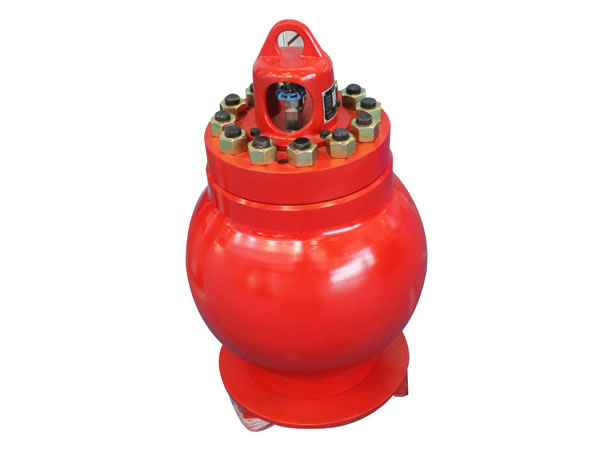
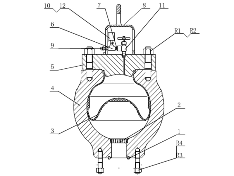
[0046] FIG. 6 is a cross-sectional diagram illustrating a hybrid reactive fluid dampener in accordance with embodiments of the present disclosure. The dampener 501a includes a spherical body 601 having an upper cylindrical turret 602 surrounding an upper opening and enclosed with a cover plate 603. The body 601 includes in inlet 604 on one side of the body 601, the inlet 604 receiving pumped fluid from the pump, and an outlet 605 on an opposite side of the body 601, the outlet 605 discharging pumped fluid into the downstream system (e.g., to a standpipe to be pumped downhole). The body 601 may be fitted with a stand 606 for support and providing flanges to (for example) bolt the stand to a mounting surface.
[0047] The body 601 may be sized to hold an amount of pumped fluid (e.g., 40 gallons) selected to provide reactive pulsation dampening under the expected operating conditions of the pump system. Suspended from the turret 602 into an interior of the body 601 is a containment diaphragm + that may be contained by a perforated containment shell 610 or held in suspension by a seal or lip 608 and filled with reactive fluid through fill valve 609. The reactive fluid-filled diaphragm 607 contributes to dampening of pressure pulsations in the pumped fluid passing through the body 601. The inlet 604 and the outlet 605 may optionally each be designed with a studded connection 611, 612 for connection to respective system piping 613, 614.
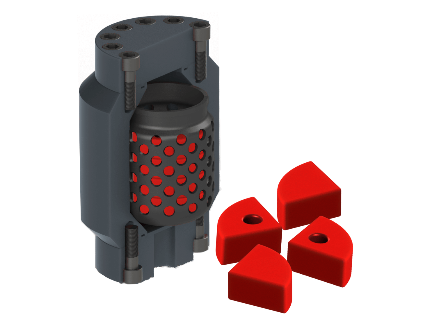
[0048] FIGS. 7A, 7D and 7G are cross-sectional diagrams, and FIGS. 7B, 7E and 7H are corresponding cut-away perspective views illustrating a combination reactive fluid and compressive elastomer dampener in accordance with embodiments of the present disclosure. FIGS. 7C, 7F and 71 are enlargements of a portion of the sectional views of FIGS. 7A, 7D and 7G, respectively, taken at area A.
[0049] Analogous to FIG. 4A, pulsation dampener 700 includes a body 701 having an upper opening receiving and sealed by a cover plate (not shown), and a lower opening. The cover plate (not shown) may be bolted to the body 701, with gasket(s) sealing an internal cavity 702 formed by the body 701, the cover plate combined. The internal cavity 702 is connected to pump system fluid piping (not shown) via the lower opening, providing a system connection to the strainer cross (also not shown). A portion 704 of a non-perforated internal diaphragm 703 within the internal cavity 702 seals the interface between the body 701 and the cover plate, instead of a separate gasket. A diaphragm stabilizer 705 serves the same function described above, and may be fastened to a metal insert molded within the material of the diaphragm 703.
[0050] The diaphragm 703, which may be formed of standard material and have a conventional shape, may be partially filled with a combination of elastomeric shapes and liquid reactive fluid. The elastomeric shapes are a compressible foam material, such as a closed cell foam. In one example, the diaphragm 703 may be filled with elastomeric wedges or elastomeric balls. However, the elastomeric addition to a liquid reactive fluid system may take any form or shape or combination of shapes. Spaces between the elastomeric shapes are filled with a liquid reactive fluid. In operation, the compressible foam material will compress under the pressure applied to the exterior of the internal diaphragm by the pumped fluid and the internal pressure of the liquid reactive fluid, creating a “gap” between the exterior of the internal diaphragm 703 and the interior of the body 701 to account for thermal expansion. The compressible foam material will quickly go completely flat when pressure is applied, thus creating the largest available volume for thermal expansion.
[0051] Alternatively, the compressible foam material may be integrated into diaphragm stabilizer 705 — that is, diaphragm stabilizer 705 may be formed wholly or partially of compressible foam material. The views of FIGS. 7A, 7B and 7C show the relative position of structures depicted when the bladder 703 contains liquid reactive fluid but before pressure of pumped fluid is applied to the exterior of the bladder 703 and before thermal expansion of the liquid reactive fluid. The internal volume of the body 701 and the size and shape of the bladder 703, after expansion due to the presence of liquid reactive fluid within the bladder 703, leaves virtually no gap 706 between the exterior of the bladder 703 and the interior surface of the body 701.
[0052] The views of FIGS. 7D, 7E and 7F show the relative position of structures depicted when the bladder 703 contains liquid reactive fluid and after initial pressure of pumped fluid is applied, but before thermal expansion. As evident, the liquid reactive fluid within the bladder 703 may be at least somewhat compressed due to external pressure on the bladder 703, resulting in a gap 707 between the exterior of the bladder 703 and the interior surface of the body 701 that will be larger than that in FIGS. 7 A, 7B and 7C.
[0053] The views of FIGS. 7G, 7H and 71 show the relative position of structures depicted when the bladder 703 contains liquid reactive fluid and after both the operating pressure of pumped fluid is applied to the exterior of the bladder 703 and thermal expansion of the liquid reactive fluid occurs. As shown, the compressible foam material within the diaphragm stabilizer 705 may be at least somewhat compressed by the increased internal pressure resulting from the thermal expansion of the compressible fluid, and the gap 708 between the exterior of the bladder 703 and the interior surface of the body 701 will be reduced relative to the gap 707 in FIGS. 7D, 7E and 7F. [0054] By providing either compressible foam material inside the bladder, or a gap between the exterior of the bladder and the interior surface of the body, or a combination of both, the effects of thermal expansion by the liquid reactive fluid within the bladder may be compensated, allowing the pulsation dampener to continue to effectively mitigate pulsations. [0055] FIGS. 8A and 8C are cross-sectional diagrams, and FIGS. 8B and 8D are corresponding cut-away perspective views illustrating a liquid reactive fluid dampener accommodating thermal expansion in accordance with embodiments of the present disclosure. FIG. 8E is an enlargement of a portion of the sectional view of FIG. 8C taken at area A.
[0056] Once again analogous to FIG. 4A, pulsation dampener 800 includes a body 801 having an upper opening receiving and sealed by a cover plate (not shown), and a lower opening. The cover plate may be bolted to the body 801, with gasket(s) sealing an internal cavity 802 formed by the body 801 and the cover plate combined. The internal cavity 802 is connected to pump system fluid piping (not shown) via the lower opening, providing a system connection to the strainer cross (also not shown). A portion 804 of a non-perforated internal diaphragm 803 within the internal cavity 802 may seal the interface between the body 801 and the cover plate, instead of a separate gasket. A diaphragm stabilizer (not shown) serving the same function described above may be fastened to a metal insert molded within the material of the diaphragm 803.
[0058] Various techniques may be used to fill the bladder 803 to a preset volume of liquid reactive fluid (less than maximum volume capacity of the bladder 803), to allow for non detrimental and nondamaging thermal expansion. This approach could involve pumping a fixed or preset volume from a supply source into the bladder (stopping the pumping either by watching a flow meter or by pumping the supply source dry), or could involve (with the top cover off) pouring a fixed volume into the bladder, then installing and securing the top cover. Alternatively, the liquid reactive fluid may be packaged within individual flexible containers such as balloon(s) that are then inserted into the diaphragm (bladder) 803 through the open top, before the top cover is secured. While a single flexible (or deformable) container (e.g., one balloon) containing the entire quantity of liquid reactive fluid determined to be needed based on the operating pressure(s) and temperature(s) may be used, it may be beneficial to use multiple flexible containers each containing a portion of that determined quantity of liquid reactive fluid, and may further be beneficial to use multiple balloons containing unequal portions. Thus, for example, for an 18 gallon fill, the liquid reactive fluid may be distributed as a set of three 5 gallon flexible containers, two 1 gallon flexible containers, and two ½ gallon flexible containers. The flexible containers, once inserted into the bladder 803, will deform to fit the interior volume of the bladder 803 and the interior shape of the pressure vessel body 801. For any of the foregoing approaches (which may be used for the other embodiments described herein), any air remaining in the internal volume of the bladder 803 may be bled out once the pump pressure is present.
[0060] In some embodiments, the size and shape of the interior volume of the body 801 and the size and shape of the molded bladder 803 may be configured for a specific volume or predetermined quantity of liquid reactive fluid (e.g., 20 gallons, or 18 gallons, etc.) used to dampen pressure pulsations in the pumped fluid. In such embodiments, the material of the bladder 803 need not stretch to accommodate the pressure of the predetermined quantity of liquid reactive fluid. This differs from gas-charged pulsation dampeners, in which the bladder normally expands to fill the interior volume of the pressure vessel when gas is inserted to a target operating pressure. The bladder size/shape and the interior volume size/shape leave a gap between the exterior of the bladder 703 and the interior surface of the body 701 to account for thermal expansion of the liquid reactive fluid. [0061] FIG. 9A is a cross-sectional diagram, and FIG. 9B is a corresponding cut-away perspective views, illustrating a liquid reactive fluid dampener relieving pressure from thermal expansion in accordance with embodiments of the present disclosure. Analogous to FIG. 4A, once again, pulsation dampener 900 includes a body 901 having an upper opening receiving and sealed by a cover plate 902, and a lower opening. The cover plate 902 may be bolted to the body 901 as shown, with gasket(s) sealing an internal cavity 903 formed by the body 901 and the cover plate 902. The internal cavity 903 is connected to pump system fluid piping (not shown) via the lower opening, providing a system connection to the strainer cross (also not shown). A portion of a non-perforated internal diaphragm within the internal cavity 903 may seal the interface between the body 901 and the cover plate 902, instead of a separate gasket. A diaphragm stabilizer (not shown) serving the same function described above may be fastened to a metal insert molded within the material of the diaphragm 904. [0062] The embodiment of FIGS. 9A and 9B also includes a fill valve 905 and a reset pressure relief valve 906. In this embodiment, the bladder 904 may be completely filled with liquid reactive fluid, such that the bladder 904 completely expands inside pressure vessel boundaries of the body 901. The reset pressure relief device 906 set to relieve the pressure exceeding a predetermined amount (due to thermal expansion) to avoid any damage and to maintain functionality.
Southwest Oilfield Products is proud to offer a full line of Pulsation Dampener Solutions. Our PD series dampeners are available in 5, 10 & 20-gallon models and are rated for 5000 or 7500psi. Installed on the mud pump strainers cross, these gas-charged drilling dampene


 8613371530291