
drilling rig mud pump knocking sound quotation

The fluid end of a duplex or triplex pump offers hundreds of opportunities for error. The results of an error in such a high-pressure system can mean (1) expensive downtime on the pump and maybe the entire rig, (2) expensive repair-replacement, and (3) possible injury or death of a crewman or a company man. Under the laws of nature, pump pistons and liners will wear, and there will be some corrosion and metallurgical imperfections, but the majority of pump failures are manmade. Theoretically, thorough training and retraining should avoid most mud pump problems. Realistically, a critical failure analysis during repair will be necessary to determine how to correct the failure. Telltale signs of trouble are distortion of piston rods, frayed piston polymer, discoloration, odor, hard-to-remove piston, rod cracks, pitting, total fracture, valve seat wear, and unsuitable external appearance.

My first days as an MWD field tech I heard horror stories surrounding what is commonly referred to as “pump noise”. I quickly identified the importance of learning to properly identify this “noise”. From the way it was explained to me, this skill might prevent the company you work from losing a job with an exploration company, satisfy your supervisor or even allow you to become regarded as hero within your organization if you’ve proven yourself handy at this skill.
“Pump noise” is a reference to an instability in surface pressure created by the mud pumps on a modern drilling rig, often conflated with any pressure fluctuation at a similar frequency to pulses generated by a mud pulser, but caused by a source external to the mud pulser. This change in pressure is what stands in the way of the decoder properly understanding what the MWD tool is trying to communicate. For the better part of the first year of learning my role I wrongly assumed that all “noise” would be something audible to the human ear, but this is rarely the case.
In an ideal drilling environment surface pressure will remain steady and all pressure increases, and decreases will be gradual. This way, when the pulser valve closes(pulses), it’s easily detectable on surface by computers. Unfortunately drilling environments are rarely perfect and there are many things that can emulate a pulse thus causing poor or inaccurate data delivery to surface. The unfortunate circumstance of this means drilling operations must come to halt until data can once again be decoded on surface. This pause in the drilling process is commonly referred to at NPT or non-productive time. For those of you unfamiliar these concepts, I’ll explain some of the basics.
A mud pulser is a valve that briefly inhibits flow of drilling fluid traveling through the drill string, creating a sharp rise and fall of pressure seen on surface, also known as a “pulse”.
Depending on if the drilling fluid is being circulated in closed or open loop, it will be drawn from a tank or a plastic lined reservoir by a series(or one) mud pumps and channeled into the stand pipe, which runs up the derrick to the Kelly-hose, through the saver sub and down the drill-pipe(drill-string). Through the filter screen past an agitator or exciter, around the MWD tool, through a mud motor and out of the nozzles in the bit. At this point the fluid begins it’s journey back to the drilling rig through the annulus, past the BOP then out of the flow line and either over the shale shakers and/or back in the fluid reservoir.
Developing a firm grasp on these fundamentals were instrumental in my success as a field technician and an effective troubleshooter. As you can tell, there are a lot of components involved in this conduit which a mud pulser telemeters through. The way in which many of these components interact with the drilling fluid can suddenly change in ways that slightly create sharp changes in pressure, often referred to as “noise”. This “noise” creates difficulty for the decoder by suddenly reducing or increasing pressure in a manner that the decoder interprets a pulse. To isolate these issues, you must first acknowledge potential of their existence. I will give few examples of some of these instances below:
Suction screens on intake hoses will occasionally be too large, fail or become unfastened thus allowing large debris in the mud system. Depending on the size of debris and a little bit of luck it can end up in an area that will inhibit flow, circumstantially resulting in a sudden fluctuation of pressure.
Any solid form of drilling fluid additive, if improperly or inconsistently mixed, can restrict the flow path of the fluid resulting in pressure increase. Most notably this can happen at the pulser valve itself, but it is not the only possible outcome. Several other parts of this system can be affected as well. LCM or loss of circulation material is by far the most common additive, but the least overlooked. It’s important for an MWD technician to be aware of what’s being added into the drilling fluid regardless if LCM isn’t present. Through the years I have seen serval other improperly mixed additives cause a litany of pressure related issues.
This specifically is a term used to refer to the mud motor stator rubber deterioration, tearing into small pieces and passing through the nozzles of the bit. Brief spikes in pressure as chunks of rubber pass through one or more nozzles of the bit can often be wrongly interpreted as pulses.
Sometimes when mud is displaced or a pump suction isn’t completely submerged, tiny air bubbles are introduced into the drilling fluid. Being that air compresses and fluid does not, pulses can be significantly diminished and sometimes non-existent.
As many of you know the downhole mud motor is what enables most drilling rigs to steer a well to a targeted location. The motor generates bit RPM by converting fluid velocity to rotor/bit RPM, otherwise known as hydraulic horsepower. Anything downhole that interacts with the bit will inevitably affect surface pressure. One of the most common is bit weight. As bit weight is increased, so does surface pressure. It’s important to note that consistent weight tends to be helpful to the decoder by increasing the amplitude of pulses, but inconsistent bit weight, depending on frequency of change, can negatively affect decoding. Bit bounce, bit bite and inconsistent weight transfer can all cause pressure oscillation resulting in poor decoding. Improper bit speed or bit type relative to a given formation are other examples of possible culprits as well.
Over time mud pump components wear to the point failure. Pump pistons(swabs), liners, valves and valve seats are all necessary components for generating stable pressure. These are the moving parts on the fluid side of the pump and the most frequent point of failure. Another possible culprit but less common is an inadequately charged pulsation dampener. Deteriorating rubber hoses anywhere in the fluid path, from the mud pump to the saver sub, such as a kelly-hose, can cause an occasional pressure oscillation.
If I could change one thing about today’s directional drilling industry, it would be eliminating the term “pump noise”. The misleading term alone has caused confusion for countless people working on a drilling rig. On the other hand, I’m happy to have learned these lessons the hard way because they seem engrained into my memory. As technology improves, so does the opportunities for MWD technology companies to provide useful solutions. Solutions to aid MWD service providers to properly isolate or overcome the challenges that lead to decoding issues. As an industry we have come a lot further from when I had started, but there is much left to be desired. I’m happy I can use my experiences by contributing to an organization capable of acknowledging and overcoming these obstacles through the development of new technology.

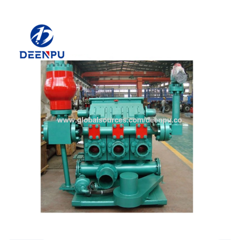
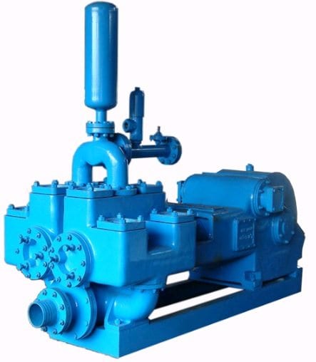
Mud pumps are reciprocation plunging pumps that are used in several drilling operations. Mud pumps are commonly employed to circulate the drilling fluid on a drilling rig. They are the important parts of any oil rig drilling operation.
Mud pumps can be divided into two categories based on the completion times of the suction and drainage in one cycle of the piston’s reciprocating motion. Mud pumps usually come in a large variety of pumping capacities and operation methods. The most preferred are triplex and quintuplex pumps. The name triplex or quintuplex refers to the number of pistons or plungers. Triplex pumps have three pistons whereas quintuplex pumps have five. However, hex pumps which have six pistons, are also being increasingly used because of their extended features and advantages. Even so, quintuplex pumps dominate the industry. The increased number of pistons results in enhanced pumping capacity and efficiency.
Despite the higher number of pistons, these pumps are not inherently complex. Quintuplex pumps have a simple design and are easy to maintain. This is also because of the evolution of technology in the drilling industry driven by the ever-increasing demand for crude oil and natural gas.
Shalepumps is based in Houston, Texas and supplies superior pumping equipment globally. We offer quality drilling mud pumps along with completion units for contractors and well service companies. Some characteristics of the drilling mud pumps provided by us are explained here.
These high-performance pumps can deliver stable fluid flow with no over-current, and pulsation. The fluid is also stirred and has a shear slurry phenomenon
The discharge pressure generated by these pumps is also irrelevant to the flow speed. The handler can adjust the displacement by a shifting mechanism or motor
The pump is designed to circulate mud or drilling fluid under great pressure down the drill hole and back up. The pump is a reciprocating model that features five pistons, hence the name quintuplex mud pump. The right degree of pressure and precision is crucial for efficient well operations. At Shale Pumps, we understand the value of a well designed and manufactured quintuplex pump, lending great focus on robust build and superior engineering quality.
Despite the fact that all mud pumps have pulsation dampeners, noise levels are likely to be high and require modifications to keep noise pollution levels low. This is important, considering the long-running hours of equipment and the need to protect personnel from constant and high noise levels. With a quintuplex mud pump, the pulsation noise and the mud telemetry noise come down by as much as half, making operations less noisy.
At Shale Pumps the designs of quintuplex mud pumps incorporate smaller footprints making the pumps more compact. Despite the smaller size of the pumps, the quintuplex pumps are rated for continuous duty with greater efficiency. The pressurized lubrication system with lubrication pumps mounted on the outside makes it easy for maintenance, reducing downtime of the equipment.
The build quality of the quintuplex mud pumps, much like the other equipment we manufacture and assemble at Shale pumps are superior, as a result of the materials, the design, and the processes employed in the assembly line. For detailed information about the service call at 713.248.3999 or mail at sales@shalepumps.com.

The article presents selected technical issues relating to drilling performed by a drillship, one type of drilling rigs. Basic problems encountered in the main function of such rigs − drilling a well − are failures of mud pumps. The authors investigate these pumps in operational conditions, aiming at development of a system for monitoring the technical condition of these pumps. Work on a diagnostic system is in progress that will permit to predict the condition of mud pump valves well in…Expand
Cavitation is an undesirable condition that reduces pump efficiency and leads to excessive wear and damage to pump components. Factors that can contribute to cavitation, such as fluid velocity and pressure, can sometimes be attributed to an inadequate mud system design and/or the diminishing performance of the mud pump’s feed system.
When a mud pump has entered full cavitation, rig crews and field service technicians will see the equipment shaking and hear the pump “knocking,” which typically sounds like marbles and stones being thrown around inside the equipment. However, the process of cavitation starts long before audible signs reveal themselves – hence the name “the silent killer.”
Mild cavitation begins to occur when the mud pump is starved for fluid. While the pump itself may not be making noise, damage is still being done to the internal components of the fluid end. In the early stages, cavitation can damage a pump’s module, piston and valve assembly.
The imperceptible but intense shock waves generated by cavitation travel directly from the fluid end to the pump’s power end, causing premature vibrational damage to the crosshead slides. The vibrations are then passed onto the shaft, bull gear and into the main bearings.
If not corrected, the vibrations caused by cavitation will work their way directly to critical power end components, which will result in the premature failure of the mud pump. A busted mud pump means expensive downtime and repair costs.
Washouts are one of the leading causes of module failure and take place when the high-pressure fluid cuts through the module’s surface and damages a sealing surface. These unexpected failures are expensive and can lead to a minimum of eight hours of rig downtime for module replacement.
To stop cavitation before it starts, install and tune high-speed pressure sensors on the mud suction line set to sound an alarm if the pressure falls below 30 psi.
Although the pump may not be knocking loudly when cavitation first presents, regular inspections by a properly trained field technician may be able to detect moderate vibrations and slight knocking sounds.
Gardner Denver offers Pump University, a mobile classroom that travels to facilities and/or drilling rigs and trains rig crews on best practices for pumping equipment maintenance.
Severe cavitation will drastically decrease module life and will eventually lead to catastrophic pump failure. Along with downtime and repair costs, the failure of the drilling pump can also cause damage to the suction and discharge piping.
When a mud pump has entered full cavitation, rig crews and field service technicians will see the equipment shaking and hear the pump ‘knocking’… However, the process of cavitation starts long before audible signs reveal themselves – hence the name ‘the silent killer.’In 2017, a leading North American drilling contractor was encountering chronic mud system issues on multiple rigs. The contractor engaged in more than 25 premature module washes in one year and suffered a major power-end failure.
Gardner Denver’s engineering team spent time on the contractor’s rigs, observing the pumps during operation and surveying the mud system’s design and configuration.
The engineering team discovered that the suction systems were undersized, feed lines were too small and there was no dampening on the suction side of the pump.
Following the implementation of these recommendations, the contractor saw significant performance improvements from the drilling pumps. Consumables life was extended significantly, and module washes were reduced by nearly 85%.
Although pump age does not affect its susceptibility to cavitation, the age of the rig can. An older rig’s mud systems may not be equipped for the way pumps are run today – at maximum horsepower.
It may be impractical to flush system piping during drilling operations. However, strainer screens should be checked daily to remove any debris or other flow restrictions.

Researchers have shown that mud pulse telemetry technologies have gained exploration and drilling application advantages by providing cost-effective real-time data transmission in closed-loop drilling operations. Given the inherited mud pulse operation difficulties, there have been numerous communication channel efforts to improve data rate speed and transmission distance in LWD operations. As discussed in “MPT systems signal impairments”, mud pulse signal pulse transmissions are subjected to mud pump noise signals, signal attenuation and dispersion, downhole random (electrical) noises, signal echoes and reflections, drillstring rock formation and gas effects, that demand complex surface signal detection and extraction processes. A number of enhanced signal processing techniques and methods to signal coding and decoding, data compression, noise cancellation and channel equalization have led to improved MPT performance in tests and field applications. This section discusses signal-processing techniques to minimize or eliminate signal impairments on mud pulse telemetry system.
At early stages of mud pulse telemetry applications, matched filter demonstrated the ability to detect mud pulse signals in the presence of simulated or real noise. Matched filter method eliminated the mud noise effects by calculating the self-correlation coefficients of received signal mixed with noise (Marsh et al. 1988). Sharp cutoff low-pass filter was proposed to remove mud pump high frequencies and improve surface signal detection. However, matched filter method was appropriate only for limited single frequency signal modulated by frequency-shift keying (FSK) with low transmission efficiency and could not work for frequency band signals modulated by phase shift keying (PSK) (Shen et al. 2013a).
Wavelet transform method was developed and widely adopted and used in signal processing to overcome limitation of Fourier transform in time domain (Bultheel 2003). Although Fourier and its revised fast Fourier transforms are powerful mathematical tool, they are not very good at detecting rapid changes in signals such as seismic data and well test data in petroleum industry containing many structure of different scales (Multi-scale structures) (Guan et al. 2004). Fourier coefficients do not provide direct information about the signal local behavior (localization); but the average strength of that frequency in the full signal as the sine or cosine function keeps undulating to infinity. Wavelet transform analyzes the signal frequency components and time segment, and fine tune sampling of localized characters of time or frequency domain. Principles of wavelet transform and de-noising technique show that signal can be divided into space and scale (time and frequency) without losing any useful information of the original signal, hence ensuring the extraction of useful information from the noised signal (Li et al. 2007). Different wavelet base parameters constructed, such as haar, db, coif, sym, bior, rbio and dmey, are suitable for different signal processing requirements. The small the scale parameter is, the higher the resolving power in frequency, suitable for processing high frequency signals; conversely, the larger the scale is the higher resolving power suitable for low frequency signal.
In processing noise-contaminated mud pulse signals, longer vanishing moments are used, but takes longer time for wavelet transform. The main wavelet transform method challenges include effective selection of wavelet base, scale parameters and vanishing moment; the key determinants of signal correlation coefficients used to evaluate similarities between original and processed signals. Chen et al. (2010) researched on wavelet transform and de-noising technique to obtain mud pulse signals waveform shaping and signal extraction based on the pulse-code information processing to restore pulse signal and improve SNR. Simulated discrete wavelet transform showed effective de-noise technique, downhole signal was recovered and decoded with low error rate. Namuq et al. (2013) studied mud pulse signal detection and characterization technique of non-stationary continuous pressure pulses generated by the mud siren based on the continuous Morlet wavelet transformation. In this method, generated non-stationary sinusoidal pressure pulses with varying amplitudes and frequencies used ASK and FSK modulation schemes. Simulated wavelet technique showed appropriate results for dynamic signal characteristics analysis.
As discussed in “MPT mud pump noises”, the often overlap of the mud pulses frequency spectra with the mud pump noise frequency components adds complexity to mud pulse signal detection and extraction. Real-time monitoring requirement and the non-stationary frequency characteristics made the utilization of traditional noise filtering techniques very difficult (Brandon et al. 1999). The MPT operations practical problem contains spurious frequency peaks or outliers that the standard filter design cannot effectively eliminate without the possibility of destroying some data. Therefore, to separate noise components from signal components, new filtering algorithms are compulsory.
Early development Brandon et al. (1999) proposed adaptive compensation method that use non-linear digital gain and signal averaging in the reference channel to eliminate the noise components in the primary channel. In this method, synthesized mud pulse signal and mud pump noise were generated and tested to examine the real-time digital adaptive compensation applicability. However, the method was not successfully applied due to complex noise signals where the power and the phases of the pump noises are not the same.
Jianhui et al. (2007) researched the use of two-step filtering algorithms to eliminate mud pulse signal direct current (DC) noise components and attenuate the high frequency noises. In the study, the low-pass finite impulse response (FIR) filter design was used as the DC estimator to get a zero mean signal from the received pressure waveforms while the band-pass filter was used to eliminate out-of-band mud pump frequency components. This method used center-of-gravity technique to obtain mud pulse positions of downhole signal modulated by pulse positioning modulation (PPM) scheme. Later Zhao et al. (2009) used the average filtering algorithm to decay DC noise components and a windowed limited impulse response (FIR) algorithm deployed to filter high frequency noise. Yuan and Gong (2011) studied the use of directional difference filter and band-pass filter methods to remove noise on the continuous mud pulse differential binary phase shift keying (DBPSK) modulated downhole signal. In this technique, the directional difference filter was used to eliminate mud pump and reflection noise signals in time domain while band-pass filter isolated out-of-band noise frequencies in frequency domain.
Other researchers implemented adaptive FIR digital filter using least mean square (LMS) evaluation criterion to realize the filter performances to eliminate random noise frequencies and reconstruct mud pulse signals. This technique was adopted to reduce mud pump noise and improve surface received telemetry signal detection and reliability. However, the quality of reconstructed signal depends on the signal distortion factor, which relates to the filter step-size factor. Reasonably, chosen filter step-size factor reduces the signal distortion quality. Li and Reckmann (2009) research used the reference signal fundamental frequencies and simulated mud pump harmonic frequencies passed through the LMS filter design to adaptively track pump noises. This method reduced the pump noise signals by subtracting the pump noise approximation from the received telemetry signal. Shen et al. (2013a) studied the impacts of filter step-size on signal-to-noise ratio (SNR) distortions. The study used the LMS control algorithm to adjust the adaptive filter weight coefficients on mud pulse signal modulated by differential phase shift keying (DPSK). In this technique, the same filter step-size factor numerical calculations showed that the distortion factor of reconstructed mud pressure QPSK signal is smaller than that of the mud pressure DPSK signal.
Study on electromagnetic LWD receiver’s ability to extract weak signals from large amounts of well site noise using the adaptive LMS iterative algorithm was done by (Liu 2016). Though the method is complex and not straightforward to implement, successive LMS adaptive iterations produced the LMS filter output that converges to an acceptable harmonic pump noise approximation. Researchers’ experimental and simulated results show that the modified LMS algorithm has faster convergence speed, smaller steady state and lower excess mean square error. Studies have shown that adaptive FIR LMS noise cancellation algorithm is a feasible effective technique to recover useful surface-decoded signal with reasonable information quantity and low error rate.
Different techniques which utilize two pressure sensors have been proposed to reduce or eliminate mud pump noises and recover downhole telemetry signals. During mud pressure signal generation, activated pulsar provides an uplink signal at the downhole location and the at least two sensor measurements are used to estimate the mud channel transfer function (Reckmann 2008). The telemetry signal and the first signal (pressure signal or flow rate signal) are used to activate the pulsar and provide an uplink signal at the downhole location; second signal received at the surface detectors is processed to estimate the telemetry signal; a third signal responsive to the uplink signal at a location near the downhole location is measured (Brackel 2016; Brooks 2015; Reckmann 2008, 2014). The filtering process uses the time delay between first and third signals to estimate the two signal cross-correlation (Reckmann 2014). In this method, the derived filter estimates the transfer function of the communication channel between the pressure sensor locations proximate to the mud pump noise source signals. The digital pump stroke is used to generate pump noise signal source at a sampling rate that is less than the selected receiver signal (Brackel 2016). This technique is complex as it is difficult to estimate accurately the phase difference required to give quantifiable time delay between the pump sensor and pressure sensor signals.
As mud pulse frequencies coincide with pump noise frequency in the MPT 1–20 Hz frequency operations, applications of narrow-band filter cannot effectively eliminate pump noises. Shao et al. (2017) proposed continuous mud pulse signal extraction method using dual sensor differential signal algorithm; the signal was modulated by the binary frequency-shift keying (BFSK). Based on opposite propagation direction between the downhole mud pulses and pump noises, analysis of signal convolution and Fourier transform theory signal processing methods can cancel pump noise signals using Eqs. 3 and 4. The extracted mud pulse telemetry signal in frequency domain is given by Eqs. 3 and 4 and its inverse Fourier transformation by Eq. 4. The method is feasible to solve the problem of signal extraction from pump noise,
$$s(t)={f^{ - 1}}S(\omega )={f^{ - 1}}\left[ {\frac{{{P_{\text{A}}}(\omega ) - H(\omega ){P_{\text{B}}}(\omega )}}{{1 - H(\omega )H(\omega )}}} \right],$$
These researches provide a novel mud pulse signal detection and extraction techniques submerged into mud pump noise, attenuation, reflections, and other noise signals as it moves through the drilling mud.

Wellbores may be drilled to locate and produce hydrocarbons. Typically, a wellbore is formed by advancing a downhole drilling tool having a drill bit at one end into the ground. As the drilling tool is advanced, drilling mud is pumped from a surface mud pit through a passage or passages in the drilling tool and out the drill bit. The mud exiting the drill bit flows back to the surface to be returned to the mud pit and may be re-circulated through the drilling tool. In this manner, the drilling mud cools the drilling tool, carries cuttings and other debris away from the drilling tool, and deposits the cuttings and other debris in the mud pit. As is known, in addition to the cooling and cleaning operations performed by the mud pumped into the wellbore, the mud forms a mudcake that lines the wellbore which, among other functions, reduces friction between the drill string and subterranean formations.
During drilling operations (i.e., advancement of the downhole drilling tool), communications between the downhole drilling tool and a surface-based processing unit and/or other surface devices may be performed using a telemetry system. In general, such telemetry systems enable the conveyance of power, data, commands, and/or any other signals or information between the downhole drilling tool and the surface devices. Thus, the telemetry systems enable, for example, data related to the conditions of the wellbore and/or the downhole drilling tool to be conveyed to the surface devices for further processing, display, etc. and also enable the operations of the downhole drilling tool to be controlled via commands and/or other information sent from the surface device(s) to the downhole drilling tool.
One known wellbore telemetry system 100 is depicted in FIG. 1. A more detailed description of such a known system is found in U.S. Pat. No. 5,517,464, which is incorporated by reference herein in its entirety. With reference to FIG. 1, a drilling rig 10 includes a drive mechanism 12 to provide a driving torque to a drill string 14. The lower end of the drill string 14 extends into a wellbore 30 and carries a drill bit 16 to drill an underground formation 18. During drilling operations, drilling mud 20 is drawn from a mud pit 22 on a surface 29 via one or more pumps 24 (e.g., reciprocating pumps). The drilling mud 20 is circulated through a mud line 26 down through the drill string 14, through the drill bit 16, and back to the surface 29 via an annulus 28 between the drill string 14 and the wall of the wellbore 30. Upon reaching the surface 29, the drilling mud 20 is discharged through a line 32 into the mud pit 22 so that rock and/or other well debris carried in the mud can settle to the bottom of the mud pit 22 before the drilling mud 20 is recirculated.
As shown in FIG. 1, a downhole measurement while drilling (MWD) tool 34 is incorporated in the drill string 14 near the drill bit 16 for the acquisition and transmission of downhole data or information. The MWD tool 34 includes an electronic sensor package 36 and a mud pulse or mudflow wellbore telemetry device 38. The mudflow telemetry device 38 can selectively block or partially block the passage of the mud 20 through the drill string 14 to cause pressure changes in the mud line 26. In other words, the wellbore telemetry device 38 can be used to modulate the pressure in the mud 20 to transmit data from the sensor package 36 to the surface 29. Modulated changes in pressure are detected by a pressure transducer 40 and a pump piston sensor 42, both of which are coupled to a processor (not shown). The processor interprets the modulated changes in pressure to reconstruct the data collected and sent by the sensor package 36. The modulation and demodulation of a pressure wave are described in detail in commonly assigned U.S. Pat. No. 5,375,098, which is incorporated by reference herein in its entirety.
In addition to the known mud pulse telemetry system 100 depicted in FIG. 1, other wellbore telemetry systems may be used to establish communication between a downhole tool and a surface unit. Examples of known telemetry systems include a wired drill pipe wellbore telemetry system as described in U.S. Pat. No. 6,641,434, an electromagnetic wellbore telemetry system as described in U.S. Pat. No. 5,624,051, an acoustic wellbore telemetry system as described in published PCT Patent Application No. WO2004085796, all of which are hereby incorporated by reference herein in their entireties. Further examples using data conveyance or communication devices (e.g., transceivers coupled to transducers or sensors) have also been used to convey power and/or data between a downhole tool and a surface unit.
Despite the development and advancement of wellbore telemetry devices in wellbore operations, there remains a need for additional reliability and wellbore telemetry capabilities for wellbore operations. As with other many other wellbore devices, wellbore telemetry devices sometimes fail. Additionally, the power provided by many known wellbore telemetry devices may be insufficient to power desired wellbore operations. Attempts have been made to use two different types of mud pulse telemetry devices in a downhole tool. In particular, each of the different mud pulse telemetry devices is typically positioned in the downhole tool and communicatively linked to a different, respective surface unit. Such wellbore telemetry tools have been run simultaneously and non-simultaneously and at different frequencies. Attempts have also been made to develop dual channel downhole wellbore telemetry for transmitting data streams via communication channels to be interpreted independently as described in U.S. Pat. No. 6,909,667. SUMMARY
In accordance with one disclosed example, a method of signal processing that includes providing at least a first pressure sensor and a second pressure sensor spaced in a drilling system and using an algorithm to separate the downwardly propagating waves from the upwardly propagating waves. In one or more examples, an algorithm may include determining a velocity of pressure signals in a wellbore, time-shifting and stacking pressure signals from at least the first pressure sensor and the second pressure sensor to determine a downwardly propagating noise signal, and subtracting the downwardly propagating noise signal from at least the signal from the first pressure sensor.
In accordance with another disclosed example, a wellbore communication system that includes a plurality of pressure sensors spaced within a drilling system along a drilling fluid flow path and communicatively coupled to a surface system and a mud pulse telemetry system positioned within a downhole tool.
FIG. 1 is a schematic view, partially in cross-section, of a known measurement while drilling tool and wellbore telemetry device connected to a drill string and deployed from a rig into a wellbore.
FIG. 2 is a schematic view, partially in cross-section, of an example telemetry system including a downhole tool having multiple mud pulse telemetry devices.
FIG. 4 is a schematic view, partially in cross-section, of a yet another example telemetry system including a downhole tool having a mud pulse telemetry device and an electromagnetic wellbore telemetry device.
FIG. 6 is a schematic view of an example drill string telemetry system including an array of pressure transducers to separate downwardly propagating rig noise from upwardly propagating measurement while drilling signals.
FIG. 9 depicts an example manner in which the example drill string telemetry system of FIG. 6 may be used to correct upwardly propagating measurement while drilling signals based on downwardly propagating noise signals.
FIG. 12 is a flow chart describing the process for correcting the pressure transducer signals for upwardly propagating mud pump noise that has been reflected by an obstacle in the drill string below the pressure transducer.
One or more example methods and apparatus described below may also utilize drill string telemetry systems and methods that enable the signal-to-noise ratios associated with measurement while drilling signals to be increased. In particular, as described in detail below, one or more pressure sensors or transducers (e.g., an array of pressure transducers) may be disposed (e.g., spaced apart based on a wavelength of a MWD signal) in a portion of a drill string that is composed of wired drill pipe. Pressure signal data collected via the pressure transducers may then be used in conjunction with one or more signal processing techniques to separate, suppress and/or cancel downwardly propagating rig noise (e.g., mud pump generated noise) from upwardly propagating MWD signals (e.g., from a MWD pulser), thereby increasing the signal-to-noise ratio of the MWD signals. In addition, upwardly propagating noise that results from the reflection of downwardly propagating noise can also be separated and removed from the MWD signals.
Referring now to FIG. 2, a mud pulse wellbore telemetry system 200 having multiple telemetry devices is shown. In contrast to the known system 100 of FIG. 1, the example wellbore telemetry system 200 includes two MWD tools 234 aand 234 b,two mud pulse telemetry devices 238 aand 238 b,two transducers 240 aand 240 b,and two sensors 242 aand 242 b.Additionally, the MWD tools 234 aand 238 bmay communicate with a single surface computer or unit 202 via the mud pulse telemetry devices 238 aand 238 b.As can be seen in the example system 200 of FIG. 2, the mud pulse telemetry devices 238 aand 238 bare identical or substantially identical, the MWD tools 234 aand 238 bare identical or substantially identical, and the devices 238 aand 238 band the tools 234 aand 238 bare positioned within a single downhole tool 201 (i.e., the same downhole tool).
Still further, while the surface unit 202 is depicted in the example of FIG. 2 as being relatively proximate to the drilling rig 10, some part of or the entire surface unit 202 may alternatively be located relatively remotely from the rig 10. For example, the surface unit 202 may be operationally and/or communicatively coupled to the wellbore telemetry system 200 via any combination of one or more wireless or hardwired communication links (not shown). Such communication links may include communications via a packet switched network (e.g., the Internet), hardwired telephone lines, cellular communication links and/or other radio frequency based communication links, etc. using any desired communication protocol.
Returning in detail to FIG. 2, the MWD tools 234 aand 238 bmay be implemented using the same device(s) used to implement the MWD tool 34 of FIG. 1. Similarly, the mud pulse telemetry devices 238 aand 238 bmay be implemented using the same device(s) used to implement the mud pulse telemetry device 38 of FIG. 1. An example of a mud pulse telemetry device that may be used or otherwise adapted to implement the devices 38, 238 a,and 238 bis described in U.S. Pat. No. 5,517,464, which has previously been incorporated by reference.
In operation, the example wellbore telemetry system 200 of FIG. 2 uses the mud pulse telemetry devices 238 aand 238 bto generate signals (e.g., modulated pressure signals) in the mud 20 flowing in the annulus 28 of the wellbore 30. These generated signals (e.g., modulated or varying pressure signals) may be sensed by one or more of the pressure transducers 240 aand 240 band/or the pressure sensors 242 aand 242 band analyzed by the surface unit 202 to extract or otherwise obtain data or other information relating to the operational condition(s) of the downhole tool 201 (e.g., one or both of the MWD tools 234 aand 238 b), conditions in wellbore 30, and/or any other desired downhole information. In this manner, communications may be established between the downhole tool 201 and, thus, between the MWD tools 234 aand 234 b,and the surface unit 202. More generally, such communications between the downhole tool 201 and the surface unit 202 may be established using uplink and/or downlink systems. Further, while mud pulse telemetry devices 238 aand 238 bare described in connection with the example telemetry system 200 of FIG. 2, other types of wellbore telemetry devices may be employed instead of or in addition to the mud pulse telemetry devices 238 aand 238 b.For example, one or more mud sirens, positive pulse mud flow telemetry devices, and/or negative pulse mud flow telemetry devices may be used.
Turning again to the operation of the example system 200 of FIG. 2, the mud pulse telemetry devices 238 aand 238 bmay send uplink signals (e.g., varying or modulated pressure signals to be conveyed up along through the drill string 14 to the surface 29) by altering the flow of mud through the telemetry devices 238 aand 238 b.Such uplink signals (e.g., varying or modulated pressure signals) are sensed or detected by the pressure transducers 240 aand 240 band/or the pressure sensors 242 aand 242 b.In particular, the uplink signals generated by the telemetry device 238 amay be detected or sensed by the transducer 240 aand/or the pressure sensor 242 a.Similarly, the uplink signals generated by the telemetry device 238 bmay be detected or sensed by the transducer 240 band/or the pressure sensor 242 b.The pressure transducers 240 aand 240 bmay be implemented using devices identical or similar to that used to implement the pressure transducer 40 of FIG. 1, and the sensors 242 aand 242 bmay be implemented using devices identical or similar to that used to implement the sensor 42 of FIG. 1.
FIG. 3 is a schematic view, partially in cross-section, of another example telemetry system 300 including a downhole tool 301 having a wired drill pipe wellbore telemetry system or device 348. In contrast to the known mud pulse telemetry system 100 depicted in FIG. 1, the example telemetry system 300 utilizes a mud pulse telemetry device 338 that is housed in a MWD tool 334 and includes the wired drill pipe telemetry system 348.
As shown in FIG. 3, the MWD tool 334 and the mud pulse telemetry device 338 may be positioned in the downhole tool 301. The MWD tool 334 may be implemented using a device that is similar or identical to that used to implement the MWD tool 34 of the FIG. 1 and/or the MWD tools 234 aand 238 bof FIG. 2. Similarly, the mud pulse telemetry device 338 may be implemented using a device that is similar or identical to that used to implement the mud pulse telemetry device 38 of FIG. 1 and/or the mud pulse telemetry devices 238 aand 238 bof FIG. 2. Additionally, the surface unit or computer 302 may be implemented in a manner similar to the surface unit or computer 202 described in connection with FIG. 2. Thus, the surface unit 302 may be operatively or communicatively coupled to the MWD tool 334 via the mud pulse telemetry device 338 and/or may be operatively or communicatively coupled to the wired drill pipe telemetry system 348 via one or more communication links (not shown). As with the example system 200 of FIG. 2, the surface unit or computer 302 may be proximate the drilling rig 10 or, alternatively, some or all of the surface unit or computer 302 may be remotely located relative to the drilling rig 10.
During operation, either or both of the mud pulse telemetry device 338 and the wired drill pipe system 348 may be used to enable communications between the downhole tool 301 (e.g., the MWD tool 334) and the surface unit 302. Depending on the particular operational mode of the rig 10 and/or downhole or other environmental conditions, the device 338 or the system 348 may be best suited to convey data to the surface unit 302. Alternatively or additionally, both the device 338 and the system 348 may be used to convey information between the surface unit 302 and the downhole tool 301 at the same time. In such a case, the conveyed information may concern the same downhole parameter(s) or condition(s) or different parameter(s) or condition(s).
FIG. 4 is a schematic view, partially in cross-section, of a yet another example telemetry system 400 including a downhole tool 401 having a mud pulse telemetry device 438 and an electromagnetic wellbore telemetry device 448. Similar to the systems 200 and 300 depicted in FIGS. 2 and 3, respectively, the system 400 includes a surface unit or computer 402 that can communicate with the downhole tool 401 and/or other downhole components and analyze information obtained therefrom. In this manner, the surface unit 402 may be operationally or otherwise coupled to a MWD tool 434 via, for example, the mud pulse telemetry device 438. Still further, as with the other systems 200 and 300, the surface unit 402 may be proximate the drilling rig 10 as shown, or some or all of the surface unit 402 may be remotely located relative to the drilling rig 10 and communicatively coupled via, for example, any desired combination of wireless and hardwired communication links to the system 400.
The mud pulse telemetry device 438 is position in the downhole tool 401 and may be implemented using the same device or a device similar to the device used to implement the device 38 of FIG. 1, the devices 238 aand 238 bof FIG. 2, and/or the device 338 of FIG. 3. Also, the MWD tool 434 is positioned in the downhole tool 401 and may be implemented using the same device or a device similar to the device used to implement the device(s) used to implement the tools 234 aand 238 bof FIG. 2, and/or 334 of FIG. 3.
While the example systems depicted in FIGS. 2-4 include certain combinations of mud pulse telemetry, wired drill pipe telemetry, and electromagnetic telemetry systems, other combinations of such systems may be employed to achieve the same or similar results. For example, a wellbore telemetry system using a mud siren, positive and/or negative pulse telemetry devices, an acoustic telemetry device, a tortional wave telemetry device, or any other telemetry device(s) could be used instead of or in addition to those depicted in FIGS. 2-4 to communicate with a surface unit or computer. Additionally, various combinations of communication links (e.g., wireless, hardwired, etc.) may be employed to provide selective communications between the surface unit and the telemetry devices to suit the needs of particular applications.
FIG. 5 is a schematic view, partially in cross-section, of still another example telemetry system 500 including a downhole tool 501 having multiple downhole components and multiple wellbore telemetry devices. As depicted in the example system 500 of FIG. 5, the downhole tool 501 includes two MWD tools 534 aand 534 b,two mud pulse telemetry devices 538 aand 538 b,two pressure transducers 540 aand 540 b,and two sensors 542 aand 542 b.
A surface unit or computer 502, which may be similar or identical to one or more of the example surface units 202, 302, and 402 of FIGS. 2, 3, and 4, respectively, may be communicatively and/or operationally coupled to the telemetry devices 538 aand 538 band/or downhole components 548 aand 548 b.As with the other example surface units 202, 302, and 404, the example surface unit 502 may be proximate (e.g., onsite) or remotely situated (e.g., offsite) relative to the rig 10 and operationally and/or otherwise coupled to the telemetry systems, MWD tools 534 aand 534 b,and/or mud pulse telemetry devices 538 aand 538 bvia any desired communication links (not shown). The MWD tools 534 aand 534 bmay be implemented using devices similar or identical to those used to implement the MWD tools 34, 234 a, 234 b, 334, and/or 434. Similarly, the mud pulse telemetry devices 538 aand 538 bmay be implemented using devices similar or identical to those used to implement the mud pulse telemetry devices 38, 238 a, 238 b, 338, and/or 438.
As depicted in FIG. 5, the downhole tool 501 houses the MWD tools 534 aand 534 b,the mud pulse telemetry devices 538 aand 538 b,and the downhole components 548 aand 548 b.In the example of FIG. 5, the downhole components 548 aand 548 bare depicted as formation evaluation tools, which may be used to test and/or sample fluid from a surrounding formation. Examples of such formation evaluation tools that may be used to implement the tools 548 aand 548 bare described in published U.S. patent application No. 2005/01109538, which is incorporated by reference herein in its entirety. As shown, the downhole components 548 aand 548 binclude stabilizer blades 552 aand 552 bwith probes 554 aand 554 bfor drawing fluid into the downhole tool 501, and backup pistons 550 aand 550 bto assist in driving the probes 554 aand 554 binto position against the wall of the wellbore 30. The formation evaluation components 548 aand 548 bmay enable various pressure testing and/or sampling procedures to be performed. Although the example of FIG. 5 depicts two formation evaluation components in the downhole tool 501, one or more than two formation evaluation components may be used instead.
In the example of FIG. 5, the wellbore telemetry devices 538 aand 538 bare operationally coupled to the respective downhole components 548 aand 548 b.However, one or more wellbore telemetry devices may be coupled to one or more formation evaluation components. For example, two wellbore telemetry devices may be coupled to the same downhole component or, alternatively, each wellbore telemetry device may be coupled to a single, respective downhole component. Additionally, a variety of formation evaluation components may be coupled to one or both of the wellbore telemetry devices 538 aand 538 b.As used herein, “formation evaluation component” refers to a device for performing formation evaluation such as, for example, sampling, detecting formation pressure while drilling, measuring resistivity, nuclear magnetic measurements, or any other downhole tool used to evaluate a subterranean formation.
The separate or individual functionality of the wellbore telemetry devices may also be used to enhance power capabilities needed to perform continuous or additional operations. Multiple wellbore telemetry devices may also be used to increase data transmission rates to the surface and/or to eliminate the need for batteries in the downhole tool. The use of multiple wellbore telemetry devices may also provide a backup system in a case where one of the wellbore telemetry systems fails or is otherwise unable to function properly. Further, in cases where two different wellbore telemetry systems and/or devices are used, alternative types of communications may be employed as desired or needed to provide more effective communications between a downhole tool and a surface unit. Still further, any desired communication medium or combination of media may be used to implement the telemetry systems described herein. For example, any combination of wireless and/or hardwired media may be used to suit the needs of particular applications. More specifically, wireless media may include drilling mud, electromagnetic signals, acoustic signals, etc., and hardwired media may include wired drill pipe and/or any other media using electrical conductors.
As noted above in connection with the examples of FIGS. 2, 3, 4, and 5, the surface units 202, 302, 402, and/or 502 may be located onsite or offsite (e.g., relative to the rig) and may be communicatively and/or operationally coupled to one or more respective downhole tools via communication links (not shown). The communication links may be implemented using any desired wireless and/or hardwired link capable of transmitting data between wellbore telemetry devices and surface units or computers. In some examples, the communication link may be coupled to a wellbore telemetry device via an intermediary device such as, for example, a pressure transducer. The communication link provides means for passing signals such as command, data, power or other signals between the wellbore telemetry devices and the surface computer. These signals may be used to control the downhole tool and/or to retrieve data collected by the downhole tool. Preferably, but not necessarily, signals are passed in real time to provide fast and efficient data collection, tool operation and/or response to wellbore conditions.
The wired drill pipe drill string telemetry system described above (e.g., the example system of FIG. 3) may be used to provide relatively high bandwidth transmission of MWD signals. However, the noise cancellation or suppression systems and methods described below in connection with FIGS. 6-14 can be used with wired drill pipe to improve the signal-to-noise ratio and increase the bandwidth of mud pulse telemetry signals. More specifically, one or more pressure transducers can be distributed or spaced along a section of wired drill pipe in an upper portion of a drill string. The pressure transducers may form a linear array that provides pressure signals that can be processed using vertical seismic profiling techniques such as velocity filtering and stacking as described below to cancel, suppress, or reduce the effects of downwardly propagating noise (e.g., mud pump noise and/or other rig noise) while enhancing upwardly propagating MWD signals (e.g., mud pulse telemetry signals). In addition, the downwardly propagating noise may be reflected from obstacles in the drill string, resulting in upwardly propagating noise. This upwardly propagating noise may also be removed from the MWD signals.
In many MWD operations, especially offshore, the MWD mud pulse telemetry is limited to a very low data rate (<<10 bits/sec). The low data rate results from a low signal-to-noise ratio, which can be caused by high noise levels generated by mud pumps and other rig-based equipment, by mud pump noise in the frequency band of the MWD mud pulse telemetry, and by the exponential attenuation of the MWD signal with depth. The pressure P(Z) measured a distance Z (m) from the mud pulser is attenuated according to P(Z)=P0eZ/Lwhere P0is the pressure at the mud pulser, and where
is an effective length. The inner radius of the drill pipe is a (m); the angular frequency is ω (radians/S); the bulk modulus of the mud is B (Pa); and the viscosity is η (centipose). The attenuation increases with frequency and with the viscosity of the drilling mud. (Reference: New Mud Pulse Telemetry Techniques for Deepwater Applications and Improved Real-Time Data Capabilities, SPE/ADC 67762, R. Hutin et al, 2001). Standard practice is to lower the mud pulse frequency to reduce the attenuation, and/or to shift the mud pulse frequency to avoid frequencies where there is high mud pump noise. In deepwater operations, there may be up to 10,000 feet (3048 m) of cold water between the rig and the seabed. The cold water increases the drilling mud viscosity, which increases the attenuation, and thus further reducing the mud pulse frequency and MWD telemetry data rate.
The systems and methods described below enable a relatively small amount of wired drill pipe (i.e., the entire drill string need not be composed of wired drill pipe) to enable relatively high bandwidth communications using a mud pulse telemetry system. In particular, the noise cancellation, suppression, or reduction systems and methods described herein utilize a relatively small amount of wired drill pipe and pressure transducers to enable a mud pulse telemetry system to communicate effectively at a higher data rate and/or at greater depths, thereby eliminating the need to use wired drill pipe along the entire drill string to achieve a high data rate and/or to communicate at greater depths. This eliminates the need to wire downhole drill string components such as positive displacement motors, jars, and heavy weight drill pipe. Furthermore, by deploying the pressure transducers near the seabed, one avoids the increased attenuation due to the effect of cold seawater on the viscosity of the drilling mud.
FIG. 6 is a schematic view of an example drill string telemetry system 600 including an array of pressure transducers 602, 604, and 606 to cancel, reduce, suppress, or separate downwardly propagating rig noise 608 from an upwardly propagating MWD signal 610. While three pressure transducers 602, 604, and 606 are depicted in the example of FIG. 6, fewer pressure transducers (e.g., one transducer in the wellbore area of the drill string) or more than three pressure transducers may be used instead. However, as described in greater detail below, the use of multiple pressure transducers may result in a greater signal-to-noise ratio for MWD signals generated by a mud pulse telemetry system than possible with, for example, a system employing only one pressure transducer. The example drill string telemetry system 600 includes a drill string 612 that is composed of a wired drill pipe portion 614 and a normal drill pipe portion 616 that is not wired. In the example of FIG. 6, the wired drill pipe portion 614 is located in the upper portion of the drill string 612 and the normal drill pipe portion 616 is located in the lower portion of the drill string 612. The example drill string 612 also includes an MWD telemetry device 618 (e.g., an MWD pulser for mud pulse telemetry) that is adjacent to a bit 620, which is disposed at the bottom end of the example drill string 612.
The pressure transducers 602, 604, and 606, an example implementation of which is depicted and described in connection with FIG. 7, may be spaced apart or separated along the wired drill string portion 614 of the drill string 612 at, for example, intervals preferably about a quarter wavelength of the telemetry signals. For telemetry performed at lower frequencies (e.g., frequencies of a few Hertz), it may be desirable to space the pressure transducers 602, 604, and 606 a hundred or more meters apart, thereby requiring one or more of the pressure transducers 602, 604, and 606 to be located in the borehole. Locating one or more of the pressure transducers 602, 604, and 606 in the borehole increases the distance between the transducers and mud pumps and/or other sources of rig noise, thereby further improving the signal-to-noise ratio of the MWD signal 610.
In general, the use of pressure transducers in connection with MWD mud pulse telemetry systems is known. One such use is described in U.S. Pat. No. 6,741,185, entitled “Digital Signal Receiver for Measurement While Drilling System Having Noise Cancellation,” the entire disclosure of which is incorporated by reference herein. Typically, in contrast to the example system of FIG. 6, these known systems locate one pressure transducer near the mud pump(s), which are primary source of acoustic noise, and another pressure transducer in the standpipe. Thus, both pressure transducers are located relatively close to the source of the rig noise. Signals received from the sensors or transducers are then typically processed or combined to cancel or reduce the effects of the noise signals generated by the mud pump(s). The separation between the transducer located near the mud pump(s) and the transducer in the standpipe affects the degree to which mud pump noise can be canceled or suppressed. A separation of about an eighth of a wavelength (i.e., the wavelength of the mud pulse telemetry signals) or about a quarter of a wavelength is typically used to provide the greatest signal-to-noise ratio for the mud pulse telemetry signals. However, in practice, such separations on the surface near the rig are usually not possible due to the low frequency and long wavelength of the mud pulse telemetry signals and the limited path length associated with the pressure equipment on the rig. Furthermore, pressure transducers 40 are normally located above the rig floor in the mud line 26. Mud pump noise is reflected by the transition from the mud line to drill pipe, which results in complex standing waves that make it difficult to filter the mud pump noise.
In contrast to the known use of pressure transducers noted above, in the example of FIG. 6, the pressure transducers 602, 604, and 606 are located on the drill string 612 in relatively downhole locations, thereby reducing the surface noise to which the sensors 602, 604, and 606 are subjected. The downhole locations of the transducers 602, 604, and 606 and the spacing between the transducers 602, 604, and 606 may be selected based on the acoustic velocity in drilling mud and the frequency at which mud pulse telemetry signals are transmitted by the MWD telemetry device 618. More specifically, the acoustic velocity in drilling mud ranges between about 1 km/sec to 1.5 km/sec, and mud pulse telemetry signals are typically transmitted at a frequency of between about 1 Hz and 24 Hz. The table below provides quarter wavelength sensor spacing in meters for different acoustic velocities and mud pulse telemetry transmission frequencies.
As drilling continues, an additional 3 km of wired drill pipe 614 is added to reach the total depth of 10 km. In this manner, the distances between the MWD pulser 618 and the pressure transducers 602, 604, and 606 do not increase with drilling. As a result, the signal-to-noise ratio of the MWD signal 610 does not degrade with depth. On the contrary, the signal-to-noise ratio may be increased by adding additional pressure sensors (not shown) to the drill string 612. Additionally, the signal-to-noise ratio improves as the distance between the pressure transducers and surface noise sources increases with depth. In deepwater offshore, the attenuation of the downwardly propagating noise due to the effect of cold water on the drilling mud viscosity is beneficial when the pressure transducers are located near the seabed.
As described in greater detail in conjunction with FIGS. 8-14 below, the signals from the pressure sensors 602, 604, and 606 may be processed to enhance the upwardly propagating MWD signal 610 while decreasing the effects of downwardly propagating surface noise (e.g., the mud pump noise 608 of FIG. 6) on the MWD signal 610. As a result, the signal-to-noise ratio of the MWD signal 610 can be increased.
The method exploits the fact that the mud pump and other noise from the rig initially propagates downwardly, while the MWD mud pulse signal propagates upwardly. This is a velocity filtering technique. The signals at the pressure transducers 602, 604, and 606 may be time-shifted corresponding to a downwardly propagating wave and averaged to estimate the downwardly propagating noise signal (e.g., an enhanced form of the mud pump noise signal 608). This estimated noise signal may then subtracted from each of the signals provided by the pressure transducers 602, 604, and 606 to provide corrected pressure signals. The corrected pressure signals are then time-shifted corresponding to an upwardly propagating wave and averaged to enhance the upwardly propagating MWD signal 610. As described further below, the time-shifting and stacking (i.e. averaging) are performed by determining the velocity of the acoustic waves or signals associated with the mud pump noise 608 and the MWD signal 610. The velocity of the acoustic waves, which may vary slowly over time, can be determined using, for example, a cross-correlation technique as described later.
FIG. 8 depicts an example manner in which the example drill string telemetry system 600 of FIG. 6 may be used to detect downwardly propagating noise. The technique described in connection with FIG. 8 uses signals associated with the pressure transducers 602, 604, and 606 of FIG. 6, corresponding to respective drill string locations Z1, Z2, and Z3 in FIGS. 6 and 8. The three vertical axes correspond to respective times T1, T2 , and T3 during which mud pump noise 608 propagates downwardly past locations Z1, Z2 and Z3 along the drill string 612. As indicated in FIG. 8, the waveform of the downwardly propagating noise remains relatively unchanged over th


 8613371530291