
f1600 mud pump piston free sample
A wide variety of bomco f1600 mud pump piston options are available to you, such as 1 year, not available.You can also choose from new, bomco f1600 mud pump piston,as well as from energy & mining, construction works , and machinery repair shops bomco f1600 mud pump piston, and whether bomco f1600 mud pump piston is 1.5 years, 6 months, or unavailable.
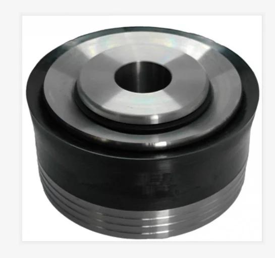
The F Series mud pumps can meet the requirements of the same manufacturing technique and quality level as those of F series mud pumps of EMSCO, IDECO, GARDNER DENVOR, OILWELL etc. Now, F series mud pumps (from F-500 to F-2200) have been produced in batches and sold to many abroad oilfields. Your order for F series mud pumps is cordially welcome.
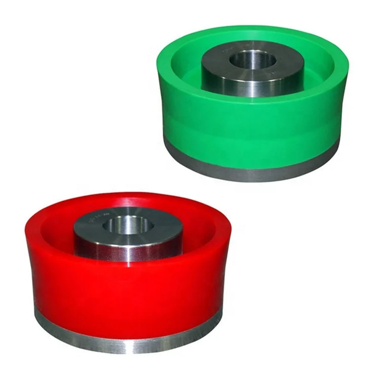
We export-orientated mud pump parts, including liners, pistons, piston inserts, valve inserts, oil seals, rod packing, fluid ends etc.. All of them meet or exceed DIN and API standards and have been exported to U.K., Germany, USA, Canada, Pakistan, Middle East, and so on.

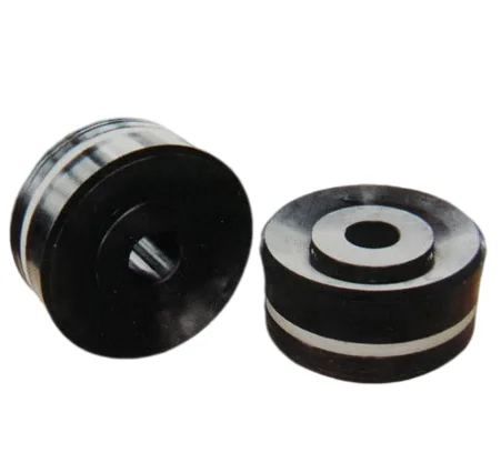
Choose a used Emsco FB-1600 Triplex Mud Pump from our inventory selection and save yourself some money on your next shallow drilling oilfield project. This Emsco FB-1600 Triplex Mud Pump is used and may show some minor wear.
We offer wholesale pricing on new Emsco FB-1600 Triplex Mud Pump and pass the savings on to you. Contact us to compare prices of different brands of Mud Pump. This equipment is brand new and has never been used.
Our large network often has surplus Emsco FB-1600 Triplex Mud Pump that go unused from a surplus purchase or a project that was not completed. Contact us to see what Emsco FB-1600 Triplex Mud Pump we have in inventory. The surplus Emsco FB-1600 Triplex Mud Pump are considered new but may have some weathering depending on where it was stored. Surplus oilfield equipment is usually stored at a yard or warehouse.
We have refurbished Mud Pumpthat have been used and brought up to functional standards. It is considered a ready to use, working Mud Pump. Please contact us for more information about our refurbished Emsco FB-1600 Triplex Mud Pump. These Mud Pump have been used and brought up to functional standards. It is considered a working Mud Pump. Please contact us for more information about the product.
Contents PREFACE···································································································································1 1 USE OF NEW MUD PUMP········································································································2 1.1 TECHNICAL SPECIFICATION AND PERFORMANCE PARAMETER············································2 1.2 INSTALLATION OF NEW PUMP ···························································································4 1.3 Suction system requirements ···················································································8 1.4 Preparation of power end···························································································8 1.5 SPRAY PUMP ASSEMBLY ································································································10 1.6 ASSEMBLY OF FLUID END PARTS ···················································································12 1.7 Dampener Assembly ································································································17 1.8 Safety Valve ···············································································································19 2 LUBRICATION ·····················································································································19 2.1 Minimum operating speeds ·····················································································19 2.2 Controlled Flow Splash System ··············································································20 2.3 Pressure Lubrication System ··················································································21 2.4 Maintenance of Lubrication System ·······································································23 3 MAINTENANCE ··············································································································24 3.1 Power End ·················································································································24 3.2 Roller Bearings ·········································································································25 3.3 Pinion Shaft Assembly ·····························································································27 3.4 Crankshaft Assembly ·······························································································28 3.5 INSTALLING CRANKSHAFT ASSEMBLY IN FRAME ·············································30 3.6 Installation of Crosshead Guides············································································31 3.7 Installation of Crosshead ·························································································32 3.8 CHECKING CROSSHEAD ALIGNMENT ··············································································34 3.9 Fluid End Maintenance·····························································································35 3.10 WELDING AND REPAIRS ·······························································································39 3.11 REPAIR TO VALVE POT COVER BORE············································································40 3.12 CHANGE OF DAMPENER BLADDER ···············································································41 3.13 APPROXIMATE WEIGHTS OF PUMP ASSEMBLIES ···························································42
4 MAINTENANCE OF PUMP·································································································42 4.1 DAILY MAINTENANCE ···································································································42 4.2 WEEKLY MAINTENANCE ·······························································································43 4.3 MONTHLY MAINTENANCE ·····························································································44 4.4 YEARLY MAINTENANCE ································································································44 4.5 OTHERS ITEMS NEED TO BE CARED IN MAINTENANCE ····················································45
Thanks for buying and using F-series mud pump of BOMCO. The differences of F-1300 and F-1600 mud pump are bearing of power end and gear pair, O.D. diameter, pump frame and fluid are the same. For convenience of customers, the instruction manual instruduces the two kinds of mud pump simultaneously. Operation and maintenance of F-1300/1600 mud pump is a complete set of material for customer which show numerous data and operation gists for operators, maintenance men and technicians. Because of the restraints of the paper length, the manual can’t describe every details. But if you operat the pump according to F-1300/1600 operation and maintenance manual, the pump can be assured for long operational use time and extended service life. All the specification and data are compiled according to Engineering Design, they should
F-1300/ F-1600 mud pump of BOMCO is a very important equipment of drilling rig, the function is transmiting drilling mud through to cool drill bits, clean bottom hole, break the rock, carry rock waste and balance formation pressure during drilling The design and manufacture of F-series mud pump is in compliance with API Spec 7K 《Specification for Drilling and Well Servicing Equipment》 1.1 Technical Specification and Performance Parameter 1.1.1 Technical Specification
50.42 44.97 39.83 35.01 30.50 (799) (713) (631) (555) (483) 46.54 41.51 36.77 32.32 28.15 *120 969 1300 1193 1600 (737) (658) (583) (512) (446) 42.66 38.05 33.71 29.62 25.81 110 889 1192 1094 1467 (676) (603) (534) (469) (409) 38.78 34.59 30.64 26.93 23.46 100 808 1083 994 1333 (614) (548) (485) (427) (372) 34.90 31.13 27.58 24.24 21.11 90 727 975 895 1200 (553) (493) (437) (384) (334) 0.3878 0.3459 0.3064 0.2693 0.2346 1 (6.147) (5.483) (4.857) (4.269) (3.719) Note:1. Based on 100% volumetric efficiency and 90% mechanical efficiency. 2. Recommended stroke and input power when pump running 130
Fig 1 F-1300/1600 mud pump overall dimensions 1.2 Installation of New Pump F-1300/1600 mud pump has been completely assembled and tested under pressure before being shipped from factory, the lubricating oil has been drained from power end as well. Before putting the pump into service, the measures and operations must be checked andperformed: In order to prevent personal injury during the operation of any maintenance or inspection procedures, this equipment must be shut down and not running, and all safeguards on prime movers, drives, etc, must be installed and in the safe position. The skid of BOMCO F-1300/1600 mud pump can adapt to all kinds mounted type, but 4
Figure 2 1.2.1 Land Installation In land installations, 8 pieces of shim plate (76mm×305mm) should be laid down along the length of pump skid indicated in Fig.2. The boards should be 300mm wider than the width of the pump skid beams. Wet or marshland may require a more stable foundation. 1.2.2 Permanent Installation Install the mud pump on drilling ship, structural base or construction of drilling platform, the skid should be shimed and fixed with bolts to prevent twisting or distorting of pump frame. The pump skids must sit solid on all shim points when bolts loose. If the pumps are installed on drilling ship, the skids are gerenally bolted to T-beams, the shims should be put properly according to Fig, 2 and 3 to prevent twist or distortion. All the shims should be wider the skid beam flanges and have a minimum length of 12″ (305mm).
If the power unit, transmission and pump skid are mounted integrally, the mud pump package must be installed on skid with T beam fitting with stop block rather than bolts to hold it in place. This way will allow the pump to “float” and minimize the deformation possibility of pump frame due to the deformation of ship platform or drilling platform. 1.2.3 Installation of transmission device The transmission between the mud pumps and the power source are V-belts or multistrand chain, should be installed accurately to assure maximum service life and the least shutdown time due to transmitting failures. When installing the drive sheave of sprocket, make sure all grease or rust preventative is removed from the shaft and the bore of the drive. Remove all burrs or rough spots from the shaft, key, and keyway. Fit key to the keyways in both the shaft and drive and install key into shaft keyway. Coat pinion shaft with a light coating of anti-seize compound or light oil and install the drive sheave or sprocket hub,tighten hub bolts as indicated below: When a wrench or length of pipe is used to increase leverage in tightening draw-up bolts, it is imperative to adhere to the wrench torque values given in the chart below. This adherence is important, because in mounting the hub, the tightening force on the bolts is multiplied many times by the wedging action of the tapered surface. This action compresses the hub for a snug fit on the shaft. If the bolt-tightening forces are extreme, bursting pressure is created in the hub of the mounted pulley; this pressure may cause the pulley to crack. The hub bolts should always be tightened alternately and progressively. Wrench Torque N·m 810
eliminated from the tight side of the belt and some of the belts on the slack side. Then increase the given center distance. For example: on 2540mm(100″) Center distance, after adjusted center distance then increase additional 13mm(1/2″). On 3180mm (150″) center distance, after adjusted center distance then increase additional 19.5mm (3/4″). Do not obtain belt tension by picking up end of pump and allowing belts to tighten under weight of pump as end is being lowered to the ground. 1.2.3.2 Chain drives 1)Installation Proper installation and maintenance of the sprocket and chain drives are essential if good service life is to be obtained. Since many factors, such as chain width, center distances, speeds, and loads must be considered when determining the allowable tolerance for sprocket alignment; no good “rule of thumb” can be applied. The chain alignment must simply be held as nearly perfect as possible. A more precise alignment can be made by stretching two steel wires (piano wire) along one face of the two sprockets, one above and one below the centerline, and moving one of the sprockets until the wires touch at four points. This will determine that the centerlines of the drives are parallel and the faces of the sprockets are square. 2) Drive chain lubrication The pump drive chain lubrication system on the majority of BS pumps is an independent system having its own oil pump, reservoir, and drive. Fill chain case to the indicated lever. SAE number of lubrication oil is refer to 《Choose of BOMCO product lubrication oil》 For temperature below -18℃ ( 0°F ) , consult a reputable lubrication dealer for recommendations. Refer to general lubrication bulletin for approved lubricants and additional specifications Since this is an independent system, it will require the same maintenance or service attention employed on any other piece of machinery, including: ——Daily check of oil lever. ——Daily check on condition of oil. ——Frequent check on oil pressure. (5~15PSI,that is 0.035~0.103MPa) ——Volume of oil being applied to chain. ——Condition of nozzles in spray tube. ——Condition of oil pump drive( V-belts or chain) Note: ① Oil pressure may be adjusted with pressure relief adjusting screw on rear of 7
the pump housing. ②Pressure drops or increase may also indicate suction and discharge filter screens need cleaning. 1.3 Suction system requirements Individual installation conditions will dictate the design of suction system. The suction of F-series pumps must have a positive head(pressure) for satisfactory performance. The optimum suction manifold pressure is 0.14 ~ 0.21MPa(20 ~ 30psi) for maximum volumetric is efficiency and expendable parts life. This head pressure is best supplied by a 6×8 centrifugal pump with 45Kw、1450rpm electric motor. This type of drive requires a device to automatically start and stop the centrifugal pump motor simultaneously with the triplex pump. On DC electric powered rigs a signal can usually be supplied from the DC control panel to energize a magnetic starter. The charging pump can also be belt driven from the triplex pinion shaft. The suction lines should be piped with valve arrangements so the charging pump can be by-passed so operation can be contined in event if charging pump failure or for maintenance. Operation without a charging pump can be improved by replacing the suction valve springs with a weaker spring. Suction desurgers are a very effective aid for complete filling of the liners and dampening pulsations in the suction line which results in a smoother flow in the discharge line. Caution: Do not pipe the return line from the shear relief valve back into the suction system as a relief valve operation will cause a sudden pressure rise in the system vastly greater than the system pressure ratings, resulting in damage to manifold,suction desurger and centrifugal pump. 1.4 Preparation of power end F-series pumps have been completely assembled and test operated before being shipped to the field. Unless otherwise instructed, the lubrication is drained from the power end, and the expendables are removed from the fluid end
Before operating the pump, the following must be performed or checked. 1.4.1 Power end lubrication Before installing lubricant, open inspection door in cover and check oil reservoir for possible accumulation of condensation, etc, and drain and flush by removing the pipe plugs on each side of the pump. Refer Item 2.Fig.7. Add the proper type and quantity of
lubrication in the power end. Refer to lubrication plate on pump frame for type and quantity required. Recheck oil level after pump has operated for a period of 15 minutes. Shut pump down and allow approximately five minutes for the oil level to equalize, Check at oil level gauge, Item 1, Fig 7.It is usually necessary for 3 gallons (10L) of oil to be added due to a certain amount being retained in the crosshead area and frame cavities. 1.4.2 Installation of Crosshead Extension Rods and Diaphragm Stuffing Box
Fig. 4 (1) diaphragm stuffing box and mud apron (2) Bolt (3) Shim (5) spring (6) double-lip oil seal (7)oil seal ring (8)O-ring (9) Locking spring (10)bolt (11)bolt
With reference to Figure 4, remove the diaphragm stuffing box (1) and rotate pump so that crosshead is at the front of the stroke, thoroughly clean the front of the crosshead and the face of the crosshead extension rod. Insert alignment boss on crosshead extension rod into the crosshead bore and tighten the retainer bolts (2) to the following torque, 350~370ft.lbs (475~500N.m), at last tightened with iron wire. Thoroughly clean mud apron and the face of frame, on the “A” place Fig. 4 is with the shim ③and tighten bolt ⑩to the following torque, 90~120ft.lbs(120~160N.m) Throughly clean bore and face of diaphragm stuffing box plate. Clean OD and flange of diaphragm stuffing box. Coat OD of diaphragm stuffing box with light oil and installO-ring seal (4), insert diaphragm stuffing box in plate bore and tighten capscrews to the following torque: 16~24N·m(12~18ft. lbs). The diaphragm stuffing box packing assembly consists of two double lip oil seal (6), an 9
oil seal ring (7), an O-ring (12) O-ring (8) and a lock spring (9). Install the assembly as follows: A: 1) Remove pressure spring ⑤ from double lip oil seal ⑥ and place seal in the outer position on the crosshead extension rod, with lip toward power end. Replace the pressure spring ⑤ in the seal lip and slide the seal into position in the stuffing box. 2) Install the O-ring 12 ○ into Oil seal ring ⑦. Insert O-ring 12 ○ and Oil seal ring ⑦ over rod and slide it into stuffing box bore. 3) Install the O-ring ⑧ in groove in stuffing box bore. 4) Install the double lip oil seal on left and right side of Figure 4 according to step 1). Caution: The double lip oil seal can be used in the inner of power end, position to replace the single lip seal, But Do Not use the single lip seal in the oyter position. 5) Install the locking spring ⑨. B: 1) Remove stuffing box ① from pump frame. Install double lip oil seal ⑥, O-ring 12, ○ O-ring 8 in stuffing box ①, then install O-ring ④ on cylndrical surface of stuffing box ①. Install guiding sleeve(tools) in front of extension rod as Figure 4, Coat extension rod and outer surface of guiding sleeve with light oil. Install stuffing box assembly on extension rod through guiding sleeve and push it to the right position, install it on mud apron with spring washer and bolt 11. ○ Note: Caution must be exercised to assure the pressure spring ⑤ doesn’t slip out of the groove in the oil seal lip, as severe scoring of crosshead extension rod can occur. Coat extension rod with light oil to facilitate installation of stuffing box assembly. 1.5 Spray Pump Assembly Spray pump assembly consists of spray pump, water tank and spray nozzle etc. it is used for flushing and cooling piston and linear during pump operated. Proper attention must be paid at all times to assure adequate cooling fluid is being applied to the piston and liner assembly. Stoppage of the cooling fluid will result in almost instant failure of the piston rubbers and possibly extensive damage to the liner bore. Stationary spray type have been used on F-series pumps Ref. Fig 5.It consists of a fixture (1), a steel pipe (2) and a spray nozzle (3), it make cooling fluid spray to piston and linear. Adjust cooling water supply to the manifold and inspect spray nozzle
to the manifold on the frame. Adjust regulating valve (Item 4 Fig .7) to apply as much water as possible to the liners without splashing back on the crosshead extension rods and diaphragm stuffing box plate. If water is allowed to splash on the crosshead extension rods, some of the water will work back into the power end to contaminate the lubrication oil. The cooling fluid is returned from the crosshead extension rod compartment to the setting chamber, and as the fluid overflows through the filter screen between the two sections of the tank, the solids are allowed to settle out. The filter screen will catch much of the foreign material floating in the fluid. With reference to Fig .6. Check condition of the cooling fluid at frequent intervals and CLEAN and FLUSH reservoir as required and replace the cooling fluid. Increasing Sand grain in Contaminated fluid will cause premature liner and piston wears
tank Note: All of the parts in this fluid end assembly are designed with metal to metal seating to alleviate friction wear from breathing action encountered in modern high pressure pump operation. For this reason it is essential that all parts be clean and free of rust, nicks and burrs before being assembled.
(1)Wear plate seal (2)Wear plate (3)linear flange (4)liner sealing ring (5)linear lock (6) Liner (7) liner locking ring (8)piston rod (9) piston (10) piston sealing (11) nut (12) Allocation disc (13) valve rod guider (14) plug board (15) cylinder head sealing ring(16) Cylinder head plug(17)-cylinder head (18) valve cover sealing ring (19)-mud apron(20) Valve cover 1.6.1 Valves and Seats Remove all three discharge valve pot covers (20), and the three cylinder heads (17) and plugs (16) seen in figure 8, and thoroughly clean all machined surfaces in the fluid end with a good cleaning solvent. Note: It’s forbidden to coat grease or oil on exterior conical surface of valve seat and interior conical surface of valve seat bore. Make sure all valve seat bores are VERY CLEAN AND DRY (free of dirt, grease, anti-rust compound, etc). Thoroughly clean and dry the valve seats and installs suction and discharge valve seats into the valve pot bores. Drive seats firmly into place with a bar and hammer to ensure contact closely. Install valves and springs and the other parts.
1.6.2 Liners Installs wear plate seal (1) in counter bore of fluid end (see Fig. 8). Slide wear plate (2) over studs until it seats against fluid end. Install liner flange (3) over studs with the starting thread at the 5 o’clock position and tighten bolts to 470~510ft.lbs (640~690N.m) torque. Note: Placing the starting thread at 5 o’clock position makes engaging the liner lock threads much easier. Place liner seal (4) in counter bore of wear plate (2). Apply thin coat of grease to ID of liner lock (5) and slide over rear of liner (6). Install two-piece liner lock ring (7) in liner groove and O-ring to hold them in position. Slide liner-handling tool over liner up against liner lock ring and tighten setscrew to secure it in place. Hoist liner assembly into position with jib hoist (for lifting liner, the maxmum hoisting weight is 500KG). Apply liberal coat of grease to liner lock threads. Align the starting thread of the liner lock (5) to the 7 o’clock position and insert the liner into the liner thread ring (3) screw liner lock in until liner seats in position. Tighten with sledgehammer on hammer lugs. 1.6.3 Piston rod Clean piston (9) and piston rod (8), making sure they are free of nicks and burrs. Install “O” ring seal (10) in groove in piston head. Slide piston head (9) on rod while observing that O-ring does not fall out of groove. Tighten piston rod nut (11) to 1625~2165 N.m (1200~1600ft.lbs.) Coating grease with. Liner I.D. and piston O.D .Check ends of piston rod and extension rod to be sure they are clean and free of burrs. Insert piston rod into liner through cylinder head opening holding piston rod centered at the rear of the liner. Drive the piston into the liner with a driving tool or a piece of hardwood and sledgehammer. Use caution as the piston rod approaches the crosshead extension rod that the dowel on the end of the piston rod is not damaged. The piston rod must be supported and the dowel guided into the pilot bore. 1.6.4 Piston rod clamps The piston rod clamps are machined as one piece and then sawed in half. The two pieces are with matching numbers on each half and connected by chain. The two pieces with the same matching numbers should always be kept together as a set. Install the clamp around the rod end flanges. Tighten bolt to the following torque values: 330N.m (245ft.ls). Before the clamps are installed, mud apron (19) should be installed on the end of crosshead rod. 14
When rods and rod clamp are new a gap in excess of 5.5mm could be present between the two halves of the clamp, this is satisfactory provided the faces of the rods are seating metal to metal. As wear occurs, the halves will pull closer together. Clamping action will be lost when a gap no longer exists. At this time clamps must be replaced. Install splash plate on rear of liner. 1.6.5 Lower valve Guide and Cylinder Head Insert the lower valve guide (13) through the alignment ring and position the guide over the valve stem. Start the lock plate (14) and draw it down, compressing the valve spring and seating the valve guide in the tapered slot. Insert allocation disc (12) into pump head hole and Install head seal (15) on cylinder head plug (16). Coating seal ring and O.D. of cylinder head plug with light oil. Push the cylinder head into open side of fluid end. Coat the light oil on threads of cylinder head. Screw the cylinder head (17) in against the plug (16). Tighten cylinder head with wrench and sledge hammer provided with pump together. Fluid leakage through the drain hole will indicate a defective seal or loose cylinder head. Should on time replace seal or tighten cylinder head. DO NOT plug weep hole as this can result in severe damage to cylinder head threads, thread rings, etc, in event of a liner seal failure. 1.6.6 Valve cover Install valve cover seal (18) into bore, and after liberal application of grease or tool joint compound to the gasket and thread area, tighten the valve covers into place, using a sledge hammer and bar 1.6.7
Fig. 9 Pulsation dampener (2) pressure gauge (3) shear relief valve (4) seal ring (5) flange bolt (6) Discharge spool (7)-gasket ring (8)nut (9)seal ring An accessory manifold connect with discharge manifold by flange. Before assembly thoroughly clean ring joint groove, install ring (4) and tighten the flange bolts (5) to 1625-2165N.m(1200-1600ft. lbs)torque. To assure uniform make-up of the ring joint connection, tighten the nuts in a criss-cross order The shear relief valve (3) is installed on the discharge manifold for the purpose of protecting the pump from excessively high-pressure overloads. The relief valve must be installed so that is will be directly exposed to the mud. DO NOT PUT ANY TYPE OF SHUT OFF VALAE between the relief valve and the manifold. Pipe the discharge side of the relief valve directly into the mud pit with as few turns in the line as possible. If the turn must be made, the elbow should be over120º. IT IS NOT RECOMMENDED for the discharge side of the relief valve to be piped into the suction line of the pump. The mounting for KB-75 pulsation dampener (1) is a flange with R-39 ring gasket. Before installing dampener, thoroughly clean ring groove and ring, and after setting dampener into place, tighten the nut (8)to 950-1265N·m (700-935ft. lbs) torque. to insure uniform make-up, tighten nuts in a criss-cross order. At each side of discharge crossis flange with seal ring ⑨R-27. Before installation, 16
thoroughly clean seal ring and groove, the torque of connecting bolt and nut is 495-660N·m(365-490 ft. lbs) in a criss-cross order . Precharge dampener before starting up pump. Dampener should be charged with nitrogen or air. (with reference this instruction manual“dampener”)
1.7 Dampener Assembly Proper installation and usage of dampener can availably reduce the pressure fluctuation of discharge system therefore obtaining more smooth fluid. For the sake of acquiring long life span of dampener, usually make pressure of pump and Precharge pressure of bladder to keep the suggestion proportion. (Precharge pressure should not be more than 2/3 of the pump discharge pressure, or a maximum of 4.5Mpa.) 1.7.1
criss-cross order. 1.7.2 Gas charging A set of gas charging device is attendant when equipment leave factory(gas charging hose assembly of dampener)please operate as following procedure: (See Fig. 11) 1. Remove guard of pressure gauge of dampener, rotate exhaust valve cover about 1/4-1/2 turn to release the air pressure existed in pressure gauge area, then remove the exhaust valve cover. 2. Connect hose to the nitrogen cylinder switch and charge valve of dampener. 3.Open the charge valve of dampener. 4. Slowly open the nitrogen cylinder valve, use this valve to adjust incoming gas of dampener. 5. When the pressure gauge of dampener indicates pressure required then shut the nitrogen cylinder valve. 6. Shut the charge valve of dampener. 7.Remove hose, cover the guard of pressure gauge, and then install the exhaust valve. In order to obtain the best results, Precharge pressure should be no more than 2/3 of the pump discharge pressure, or a maximum of 4.5 Mpa. (650psi)
Fig. 12 (1)Connector (2)Retainer Ring (3)Piston Assy. (4)Valve Body (5Piston Rod (6) cushion (7)Pin (8)Lock Spring (9)Safety Cap (10)Shear plate (11)Shear Pin (12)Warning Plate (13) Pin (14) Retainer Ring (15)Name Plate (16)Cotter Pin (17)Nut (18)Cap screw (19)Bolt (20)Nut(21)Cap screw JA-3shear pin safety valve drawing refers to Fig 12, When the pump pressure exceeds the rated pressure, the force acted on piston ○ 3 jacks-up the shear plate 10and ○ break down the shear pin, finally the mud flow is discharged rapidly. Change the position of shear pin can adjust the release pressure of JA-3 safety valve. The operation is simple and reliable Each work pressure is marked on the shear plate. When adjust the pressure, just insert the shear pin in the relevant hole according to the given pressure. Note: Only one shear pin can be inserted in the shear plate! Pressure must be changed if the liner size changed.(Refer to Section 1.1.2 function parameter). Wire, welding rod or other material are strictly forbidden, otherwise the valve pressure will be affected and may cause an acc a reverse accident. 2
Proper lubrication of the moving parts in any piece of machinery is the most important single factor affecting its ultimate life. To obtain maximum trouble-free service life from the power end, it is necessary to perform routine maintenance care and inspections to insure the proper amount of clean lubricant is being provided. 2.1 Minimum operating speeds The F-Series pumps utilizethe controlled flow oil bath splash and pressure system to 19
lubricate the entire power end. The type of pressure system provided in each individual pump will govern the minimum SPM at which the pump can be operated. As shown in Fig. 13, F-1300/1600 mud pump can be operated at 25 SPM. Provided(at a pressure of 0.035Mpa).
Fig. 13 Note: The pressure lubricating system can be provided with an externally mounted oil pump driven through V-belts or internally mounted oil pump driven from the main gear. When an internally mounted oil pump is used, the direction of rotation of the pinion shaft must be as shown in Fig. 13. 2.2 Controlled Flow Splash System The controlled flow splash lubrication system is the same for all F-Series pumps, regardless of the type of oil pump drive provided for the pressure system. In the controlled flow splash system, the main gear picks oil up from the reservoir, and when the teeth mesh with the pinion, the oil is displaced into various troughs and compartments in the frame. With reference to Figure 15, the oil thrown into oil trough (7) is directed through the oil tube (8) to the two pinion bearings Oil passage from the of the crosshead guide compartment to the crosshead bearing is shown in Figure 14, Oil accumulates in the compartment over the crossheads. The oil runs through the nipple (1) into the crosshead retainer to the oil passages (5) and on to the crosshead pin bearing. As noted, the duplicate set of oil passages (5) in the crosshead pin permits the crosshead pins to be rotated without having to give attention to hole alignment. This permits the installation of crosshead pins from either direction.
2.3 Pressure Lubrication System The pressure lubrication system, incorporating the oil pump for the F-series pumps, is shown in Figure 15: In this system, filtered oil is supplied to the pump through the suction filter (1) and is discharged from the pump into the manifold block (2) and nozzle (3A). Oil is distributed to the main bearing oil line (4) and the crosshead compartment manifold block (4A) located above the crosshead compartment. The crosshead compartment manifold block (4A) distributes oil to the crosshead, crosshead bearings and extension rods. A pressure gauge (5) is mounted on the back wall of the frame to show oil pressure being maintained in the manifold block. The oil pressure will, of course, vary with the speed of the main pump, however if a sudden pressure drop or increase occurs, refer to the section on maintenance of lubrication system for possible cause. A pressure relief valve (6) is mounted to the manifold block (2) to keep excess pressure from damaging oil pump and drive. The relief valve work pressure should be 0.27Mpa (40 PSI). When installing the internally mounted oil pump(item 9,Fig 15), position pump so that the back face of the drive gear is flush and parallel with the edge of the main gear, and
(1) Filter (2) manifold block (3) oil line (3A) spray nozzle (4) main bearing oil line (4A) Manifold block (5) pressure gauge (6) relief valve (7) oil trough (8) oil tube (9) Lubrication pump
A typical layout for the pinion shaft driven oil pump is shown in Fig. 16. The oil pump (1) is piped into the oil system through the suction and pressure connections on the bottom inside wall of the power frame. Do not adjust V-belt drive (2) too tight. Over tightening can cause premature failure of the pump. To prevent possible injury, always install guard (3) over V-belts before putting pump into service.
2.4 Maintenance of Lubrication System Adequate lubrication of the moving parts is, as stated, the most important single factor affecting the ultimate service life of the pump, care and maintenance of the system is the sole responsibility of the operator or crew to which it has been assigned, and the extent to which this is applied will determine the amount of trouble – free service life that will be obtained. 2.4.1 Lubrication specifications The lubricant recommendations is shown on the nameplate on the side of the pump, also can refer to 《BOMCO lubrication oil selected guidebook》. All these materials are the result of extensive long-term field tests and can validate to wear away (include gear, bearing and guild cross head). Substitutions should be made only in extreme emergencies. 2.4.2 Oil reservoir capacity: Oil reservoir capacity: 379L (100 U.S. Gallons) 2.4.3 Routine check Once each tour, check and maintain oil lever at full mark on the bayonet gauge. Pump must be shut down and allowed to stand idle for approximately five minute-to allow oil lever to equalize. Once each six month, or more often if oil becomes contaminated with abrasive particles or corrosive compounds, drain and flush the oil reservoir and pour new lubricant. Oil drains are located on eighter side of the pump frame. During the flushing procedure, thoroughly clean the oil troughs and the compartment in top of the crosshead guide. Also clean or replace the filter element in the air breather cap and clean suction screen. Remove covers from settling chamber and purge out contaminants before adding new oil. Routine inspection on condition of oil should be made as condensation of moisture in the air, instrusion of mud, water or dirt, can necessitate a more frequent oil change. A settling chamber is located in the forward area of the power end floor, The contamination in the oil splashed into this area should be drained from clean out covers. Once each month, remove clean out covers on both sides of pump to drain contaminated oil from settling chamber. Approximately 15-gallons of oil will be lost; replenish the main reservoir to compensate for amount drained out. Once each week, remove one of the lower 1/2” capscrews that secure the clean out cover to the frame to drain off water condensate.
Once each tour, check oil lever in main reservoir. Maintain at full mark on dipstick to the manifold block. If loss of pressure occurs, check for: —— Clogged suction screen —— low oil lever —— slipping V-belt drive —— Broken or loose connections —— Damaged or worn oil pump —— Defective relief valve For an abnormal increase in oil pressure, check for: —— Plugged oil lines —— Contamination causing oil to be viscous —— Relief valve inoperative —— Defective gauge —— Other conditions 3
assembly section for bolt torque requirements.) 3.1.3 Oil Lines Check all oil lines to insure they are intact and free of obstructions. Check the suction hose of the gear pump to insure it is not damaged and staved. 3.1.4 Suctiong Filter Check condition of suction filter.Clean and repace as necessary. 3.1.5 Main Bearing Cover Remove the main bearing cover and check the tightness of the main bearing 24
increase ,immediately contact the manufacturer for a thorough inspection of the gear. 3.1.7 Crosshead Pin Bolts and Crosshead Guides Remove cover and check condition of the crosshead pin bolts and safety wires(Remove the back cover when check the center crosshead pin blots, meantime locate the eccentric strap at the back dead position).Tighten crosshead bolts 24×70(Fig 14 item 3),torque is 225~240N·m (165~175ft. lbs) DO NOT EXCEED THE ABOVE VALUES, USE TORQUE WRENCH. If the crosshead or guide shows abnormal wear or scoring, replace immediately as the metal particles can cause damage to the bearings etc.Excess wear can also cause rapid wear to the piston and liners. 3.1.8 Lubrication and Reservoir Check condition of the oil and cleanliness of the oil reservoir.Service oil system as described in the lubrication section of this manual. 3.2 Roller Bearings F series mud pump use roller bearings which is a precisely built machine whthin itself; therefore, careful handing is required in order to obtain the long service load carring characteristics associated with anti-friction
Note: T-Shrink Range,L-Space Range The pinion is an intergral part of the shaft, leaving only the installation of the bearings and wear ring to complete the assembly. (Refer to Fig 17)。 The running clearances of the bearins are predetermined by their preision fit to the shaft and the bearing carrier. When perfoming maintenance or overhaul, makd sure the fits show in Chart II are obtained. Installation of pinion shaft assembly in pump: 1)Insure pinion bearing carrier gasket ①and oil seal carrier gasket②are in place and in good condition. 2)Installation the pinion bearing carrier③ and the oil seal carrier④, make sure the oil collectin box ⑦ at a right place to positon oil throughs and align drain holes. 3)Remove burrs,dents or gouges from the OD of the oil seal spacer before sliding the oil seal carrier into place.Exercise care when sliding lip of seal over end of shaft to prevent it from being damaged by the sharp edge of the keyway. Also pay particular attention to insure oil seal lip IS NOT TURNED UNDER by edge of spacer when sliding seal onto the spacer. 4)Tighten pinion bearing carrier bolts ⑥to the torque: 110~215N.m (80~160ft.lbs) 27
inner race retainer 14 ○ .Tighten the retainer bolt⑧, the torque is60 ~ 90N·m (44 ~ 66ft.lbs). 7) Install left eccentric bearing,eccentric strap etc.(Refer to item 6). 8) Place main bearings⑨ into the main bearing carriers(10 RH and 11 LH),and install outer race retainer12. ○ Tighten bolts15 ○ to the torque 60~90N·m (44~66ft. lbs) 9) After inatalling the two main bearings16,shrink ○ main bearings⑨ on each end of the shaft.Install inner race retainer 17 ○ and retainer bolts 18 ○ , tighten the bolts to the torque60~90N·m (44~66ft. lbs) 3.5 INSTALLING CRANKSHAFT ASSEMBLY IN FRAME In order to obtain a more precision fir between the main bearing housing and the frame bore on F-series pumps, the installation procedure outlined below are to be followed: (Refer to Fig 19)。 1) Place a piece of wood between eye of eccentric strap and crosshead guide(Fig 20), to protect guide from scoring or gouging as the straps are slidjing into position. 2) Rotate the main bearing carrier so that the two flat spots
pump and rotated 180°to provide a smooth surface for the bottom of crosshead.The center crosshead can also be rotated 180°and install the crosshead pin in the opposite side.Install the crosshead pin retainer ②before install the crosshead pin into the crosshead. 4) Install crosshead pin retainer② and retainer bolts③, and rotate pin until the four crosshead bolt holes are in aligenment.Install fout bolts and make up hand tight.Reger to Fig 21.Make sure the oil slot on the retainer up.
In order for the pistons to run normally in the liners, the crosshead must travel in a straight line along the horizontal centerline of the frame bore. To check and adjust crosshead alignment, proceed as follows: 1) Remove diaphragm stuffing box from the diaphragm plate, (Fig, 21). Do not remove the plate. 2) Position crosshead at the extreme front of its stroke. With inside calipers or telescoping gauges, accurately measure the distance from the diaphragm plate bore to the crosshead extension rod at the top and bottom. Compare the two measurements to determine the position of the rod relative to the centerline of the bore. 3) Rotate pump to extreme rear of stroke and take measurement again at the same place. Compare these measurements to the ones taken at the front of the stroke to determine if crosshead is running horizontally. 4) If the centerline of the extension rod is more than 0.38mm (0.015″) low in the diaphragm plate bore, shims should be inserted under the lower guide to bring the extension rod back to center, provided there is ample clearance between the top of crosshead and upper crosshead guide. It is normal for the lower guide to wear more at the rear due to heavier loading at this point because of the angle of the eccentric strap. It is permissible to shim the guides on a taper if the guide can seat on the frame firmly. Do not shim guides to less than 0.50mm (0.020″) clearance between upper guide and crosshead. The large crosshead clearances are acceptable due to 34
characteristics of triplex pump , the crosshead pressure is always loaded on the lower guide when the pump works postively. Note: If the mud pump must run in reverse situation.The clearance between the upper guide and crosshead should be within the range 0.25 ~ 0.40mm (0.010-0.016in) 5)
For many years, the fluid end of a pump was considered a non-wearing part which did not cause any concern other than possible infrequent repairs or replacements resulting from fluid cuts or washouts. However, the higher pressures of the present-day drilling requirements have resulted in higher stresses being imposed on the fluid end which, when combined with the corrosive characteristics of the drilling fluid, have resulted in the demand that more and better maintenance be given to the fluid end parts and pieces if a reasonable operating life is to be obtained. A few of the obvious points is as follows: 1) Make sure all valves on the discharge side of pump are opened before pump is put into operation. Kicking pump in against a closed valve can often be the start of a fatigue crack. An open crack may not necessarily occur at the precise moment, however, a small crack could occur and start the process of “corrosion fatigue failure” 2) Do not engage pump clutch when prime mover is running at a high rate of speed. Which can cause undesirable shock loads against both power end and fluid end. 3) Properly maintain pressure relief valve to assure it is set for the pressure rating on the liner size being used. Refer to the description about the relief valve. 4) Do not operate the pump for an extended period of time if a severe fluid knock is present.
5) Properly prepare fluid end for storage. When pump is to be shut down or not operated for a period of ten days or more, it is recommended that the fluid end parts such as liners, pistons, rods, etc, be removed from the pump and the fluid end be flushed out completely with fresh water, After a thorough flushing, apply grease or a rust preventative to all of the machined surfaces such as valve pot cover threads, valve pot cover gasket surfaces, valve seats, liner bores, etc. The parts removed from the pump including liner, piston rods, etc., should of course be protected correctly. This will not only extend the life of the fluid end through resistance to corrosion, but will also protect the expendable parts still left in the pump and maintain them in good condition for installation in the pump at the next start-up period. The fluid end assembly for these triplex pumps consists of three forged cylinder blocks, complete with valve covers and cylinder heads, a suction manifold, and a discharge manifold.
4 Maintenance of Pump Proper maintenance of pump in time is the necessary measure to assure the pump working and prolong the service life. For using any pump, maintenance should be paid more attention to. NAME UNIT F-1300 F-1600 F-1300
4.1 Daily Maintenance 1) After stopping the pump, check the oil level of power end, at least once a day. If chain drive is used, the oil level of chain box should be checked too. 42
2) Check the indication of lubricaton system pressure gauge, if the pressure is very low (lower than 0.035Mpa) or no pressure, check if the suction and discharging filter screen are plugged. 3) Make sure the suction dampener work normally. 4) Check if the pressure of discharge pulsation dampener meets the requirements. 5) Check the reliability of relief valves, if necessary, they should be changed. 6) Check the working situation of liner and piston, it’s normal that a little mud is taken out with piston. If there is leakage, the piston should be changed. Check the abrasion of liner inner bore. If the abrasion is severe, the liner should be changed in time. 7) Check the liner compartments of the frame. The mud and contamination should be cleaned in time. 8)Check the water tank of spray pump. The water or oil should be supplied if there is not enough. The polluted water should be changed and the water tank should be cleaned. 9) Loose the coupling of piston rod every day, check if the taper face of coupling and the junction face of piston rod and extension rod are clean, rotate the piston rod a quarter round and tighten. In that case, make the wearing face evenly and prolong the service life of liner and piston. 10) Before tightening the valve cover, coat grease on the valve cover threads and check the cover for loosing every four hours. 11) Check the alarm bore of valve cover seal and liner seal (including the seal between the wearing plate and cylinder). If there is mud leaked, change the relative seal ring. 4.2 Weekly Maintenance 1) Disassemble the valve cover and liner head every week, and clean them. Coat the extreme pressure lithium base grease (compound). 2) Check the inner sleeve of valve guide. If there is sharp abrasion (the clearance between the valve guide pole and guide exceeds 3mm), it should be changed to avoid the guide failing to guide the valve motion in the right way and accelerating the abrasion of valve.
3) Check the valve and valve seat, change the worn or pierced valve body, valve rubber and valve seat (when changing the valve seat, the valve body should be changed together). Check the spring and change the broken or inelastic spring. 4) Check the locknuts of piston. The corrosive or damaged locknuts should be changed. (The seal rings in the locknuts will fail after the locknuts are tightened three times in normal situation.) 5) Drain water one time from the plug of drain flange until oil comes out. 6) Check and clean the filter screen in the lubricating oil line. 4.3 Monthly Maintenance 1) Check all stud bolts and nuts of fluid end. Including thread ring nuts, nuts connecting the cylinder to frame, the bolts and nuts on the suction and discharge manifold. If they are loose, tighten to the required torque value. 2) Check the seal rings in the packing box of extension rod. The worn one should be changed. Usually, change it at least once every three months. Attention should be taken to the oil seal position when changing (the lip should be inward). 3) Remove and clean the filter in the discharge strainer assembly. 4) Change the dirty oil in the oil reservior of power end and the oil groove of crosshead every six months. Clean these oil grooves at the same time. 4.4 Yearly Maintenance 1) Check the wear condition of crosshead and guide surface; Check if the crosshead guide is loose; Check if the crosshead running clearance conforms to requirements. The clearance can be adjusted by adding shim under the guide or rotating the crosshead 180°. 2) Check the whole pump completely every two years or three years;check if the main bearing, eccentric strap bearing, crosshead bearing, pinion shaft bearing are worn or outworn. They should be changed if they can’t be used any more. 3) Check the wear of gears. If they are worn sharply, turn around the pinion shaft and crankshaft shaft to use the face that isn’t worn.
1) Before installing the clamp for extension rod and piston rod, clean the match taper surface. 2) When changing the liner, the liner seal ring should be changed together. 3) After stopping the pump in winter or stopping for more than 10 days, the mud in the valve compartment and liner should be discharged and cleaned completely. 4) Cover each inspection hole to avoid the sand dropping into the lubricating oil. 5) The discharge pulsation dampener is only allowed to charge inert gas (such as nitrogen) or air. No inflammable and explosive gases are allowed such as oxygen, hydrogen etc.
Maintenance Check the oil level after stopping the pump. If it is too low, it should be added to required level. Check if the reading of pressure gauge of lubricating oil pump is normal. When the pressure is too low, the cause should be found at once. Check if the suction dampener works normally Fill the cooling lubricant into the spray pump water tank when it’s not enough. Change it when it deteriorates. Check the liner compartments. Clean it when necessary. Before tightening the valve cover, coat grease on the valve cover threads and check the cover for loosing every four hours. Check the piston and liner for leakage, change them when necessary. Loose the coupling of piston rod one time daily, rotate the piston rod a quarter turn and then tighten the coupling back again. Check if the reliefe safety valves are reliable. Check if the pre-charging pressure of discharge pulsation dampener is normal when stopping the pump. Observe the alarm bore, if the mud is discharged, the related seal ring should be changed( total 4 points in one pump). Disassemble the valve cover and liner head every week, and clean them. Coat the extreme pressure lithium base grease (compound) Check the inner sleeve of valve guide.If it’s worn, change it in time. Check the suction and discharge valve body, valve seat and valve rubber, change the damaged one. Check if the locknuts of piston are corrosive or damaged. Change if they are damaged (normally, change after using three times). Check the filter screen of lubricating system. Clean it if it is plugged. Loosen the plug of drain flange, discharge the dirt and water in the oil pool. Check the bolts of fluid end, the loose or damaged bolts should be tightened or changed. Check the seal ring in the packing box, the worn one should be changed. At least change one time every three months Check the filter in the discharge pipe. Clean it if it is plugged. Change the dirty oil in the oil pool of power end and crosshead oil groove and clean the places every six monthes. Check the wear of crosshead. If necessary, use the crosshead after rotating 180°. Check if the guide is loose and the crosshead clearance conforms to requirements, otherwise, they should be adjusted. Check the wear of tooth face of the pinion and the gear, if necessary, use them reverse face. Check if the pinion shaft and crankshaft are all right. Measures should be taken if there is abnormal phenomena. Check the bearing of power end. The damaged one should be changed. Check the seal of rear cover and crank shaft end cover. If the seal is not good, it should be changed.
5 Troubleshooting During the running of the pump, if there are some troubles, the reason should be detemined and the trouble should be solved. Otherwise, they will affect the normal working of the pump.
Trouble 1. The pressure readings become low and the discharge reduces or no mud discharges. 2. Uneven discharge. The pressure gauge fluctuates. The charging piping has abnormal noise. 3. There is severe slap in the liner. 4.The mud leakage from the alarm bore of valve cap, cylinder head and liner seal. 5. The discharge pulsation dampener can’t be charged or it leaks after charging.
Cause 1. The charging piping is not sealed off and the air gets into the pump. 2. The suction filter screen is plugged. 1. A piston or a valve is worn out or damaged. 2. There is air in the pump cylinder. 1. The piston nuts are loose. 2. The liner cover is loose. 3. The suction is not good caused water hammer. 1. The valve cover or cylinder head is not tightened. 2. The seal ring is damaged. 1. The charging connector is plugged. 2.The bladder of the pulsation dampener is broken. 3.The needle valve is not sealed. The discharge filter is plugged. 1.The oil pipe or oil port is plugged. 2.The lubricating oil is too dirty or deteriorated. 3.The rolling bearing is worn or damaged. 4.The lubricating oil is too much or too little. 1. The crosshead guide is worn out sharply. 2. The bearing is worn out. 3. The guide is loose. 4. There is water hammer on the fluid end.
Troubleshooting 1. Tighten the flange bolts of charging pipes or change the gasket. 2. Stop the pump and clean the suction filter screen. 1. Change the damaged piston and check the valve to find if it’s damaged or plugged. 2. Check if the charging piping and valve cap are sealed off. 1. Tighten the piston nuts. 2. Tighten the liner cover. 3.Check the reason of improper suction. 1. Tighten the valve cover or cylinder head. 2. Change the seal ring. 1.Clean the connector. 2.Change the bladder. 3.Repair or change the needle valve.
6 Storage Information 6.1 When the pumps are not used for a long time, they should be stored. 6.2 Before storing, clean it carefully, empty each part of fluid end and clean it with water. 6.3 Drain off the lubrication in the power end completely and remove the deposits. 6.4 Coat viscous lubricants on the finished surface of all bearings, crossheads, gears, piston rods, extension rods etc. 6.5 Coat grease on the machined surface of each parts of fluid end.
6.6 Cover the suction inlet and discharging outlet with blind flange. 6.7 The inspecton cover, rear cover and the inspection hole cover of crosshead should be covered. 7 Explains for Ordering Provided range of mud pump -Completely MUD PUMP basic parts; spray pump; pulsation dampener; safety value; tools; spare parts for one time change of rubber seals. -Not including pulley and big skid. -If not be special required by users, spray pump is droved by belt and lubrication pump is inner droved style by big gear. -Normally, 6 3/4” liners and pistons are assembled in the pump when it is transported to users. 8 Use of Special Tools 8.1、Hydraulic Valve Seat Lifting Tool
Note: F1300/160 pump will be equipped with belt-driving piston and liner wash assembly. BOMCO can supply electrical piston and liner wash assembly according to customer’s requirement.
CHARGING INSTRUCTIONS 1. Remove dampener gauge cover. Bleed off any existing pressure in gage area by turning purge valve cap approximately 1/4 to 1/2 turn. Remove purge valve. 2. Connect charging hose to dampener charging valve and nitrogen cylinder valve. 3. Open dampener charging valve. 4. Open cylinder valve slowly. Use this valve to regulate flow to dampener. 5. When dampener gauge shows desired charging pressure, close cylinder valve. 6. Close dampener valve. 7. Remove hose from dampener charging valve and replace gage cover. For best results. dampener precharge pressure should be not more than 2/3 of pump discharge pressure. Maximum

SCOPEThis specification covers the preservation and storage procedure for shipment of new-buildNOV Triplex Mud Pumps shipped from the manufacturing plant.This specification is intended to provide preservation of new-build NOV Triplex Mud Pumpsfor six (6) months from the shipment of the mud pump from the manufacturing facility. If apump is to be stored for a period of time exceeding six (6) months, additional precautionsshould be taken as outlined in this specification.National Oilwell Varco recommends that all pumps are inspected for any signs of corrosionand for proper preservation at a minimum every three (3) months for pumps stored outsideand every six (6) months for pumps stored indoors.Sub-tier: National Oilwell PS-3081
MANUFACTURING PLANT PRESERVATION PRIOR TO PAINTDrain all water and clean out liner wash tank. Remove drain plug in bottom of liner washpump and drain water then reinstall plug. Remove discharge flange from liner wash pumpand pour one (1) pint of inhibiting oil-based concentrate (Cortec VpCI 329 Vapor CorrosionInhibiting oil-based concentrate or equivalent) into liner wash pump. Rotate two (2)revolutions by hand to distribute the product. Re-install discharge flange.Drain all oil from pump power end sump and remove crosshead covers and inspectioncovers. Clean out oil sump as per National Oilwell PS-3081 (Mud Pump Cleanliness).Spray all internal machined parts of power end and crosshead area with inhibiting oil-basedconcentrate (Cortec VpCI 329 Vapor Corrosion Inhibiting oil-based concentrate orequivalent). Rotate pump turn and re-spray. Pour quantity of inhibiting oil-basedconcentrate specified in the table below into power end sump.Mud Pump Models
For pumps equipped with chain drives, spray internal machined parts inside chain caseswith inhibiting oil-based concentrate (Cortec VpCI 329 Vapor Corrosion Inhibiting oil basedconcentrate or equivalent).
Replace all guards and seals as necessary using specified gasket material and sealingcompounds.Remove fluid end valve covers, seals, valves springs and seats and treat internal cavitiesof fluid ends, discharge manifold, discharge strainer block and suction manifold with rustpreventative (CRC SP400 or equivalent). Coat threads with anti-seize (KOPR KOTE10002 or equivalent) and coat bottom side of valve cover with rust preventative. Reinstallseals and fluid end valves covers hand tight. Customer liners, pistons, piston rods, valves,seats, springs and liner retention parts are not used for plant testing. These expendablesare checked for preservation when packed and then shipped with the loose parts.
MANUFACTURING PLANT PRESERVATION AFTER PAINTRemove breather and pack with loose parts for later shipment with pump. Seal breatherhole with a greased solid plug. Affix a warning label near the breather opening (see Exhibit1).Spray all external unpainted machined parts of pump with rust preventative (CRC SP400 orequivalent).Cover large diameter pipe and other openings with hardboard and protective plastic wrap.Liner bushing openings shall also be covered and sealed.Seal all other pipe work (air, water, and electrical) with plastic caps of the correct size andstyle. Electrical J-boxes are to be encased in protective plastic wrap. Place two (2) onepound bags of desiccant inside each J-box before sealing with tape. Wrap pressuregauges with bubble paper and plastic.Tape or band down loose hinged guards and inspection covers.Spray all machined unpainted loose parts and expendables to be shipped with pump withrust preventative (CRC SP400 or equivalent). All parts will be wrapped or boxed to preventdamage.Affix one (1) warning label (see Exhibit 2) to the power end pump cover and one (1)warning label on the fluid end assembly of the pump. Affix warning labels on each loosepart container. In cases where the equipment will be b


 8613371530291