
mud pump charging system factory

Mudslayer Portable Mud System built by a well driller for well drillers, saving their backs and their bottom line. This shaker system was designed by Jim LaPorte, professional water well driller in California for 30 years. Jim realized he needed a reliable mud system that did not require an enormous amount of training and extensive technical education to operate.
The idea of the MudSlayer was born. This mud shaker does not require an experienced user that has a P.H.D. in engineering to operate. This baby is simple, affordable and dependable. It has the power to move the mud, remove the solids and make your well drilling more productive. Saves you time money and stress, and maximizes safety and productivity
Our unique dual screening system is dollar for dollar the best one on the market. The performance of post tension screens at standard screen prices. Our self cleaning tank design eliminates the manual shoveling, stirring and constant baby sitting of the pit. The Caterpillar power plant is quite, reliable and economical.
We have a two axle towable trailer to move this unit easily and where it needs to go and electric brakes for extra stopping power. Four hydraulic outriggers come standard and make your setup quick and easy. The 500 G.P.M. lift pump is also mounted on a hydraulic boom to insure safety and reduce the risk of back injury.
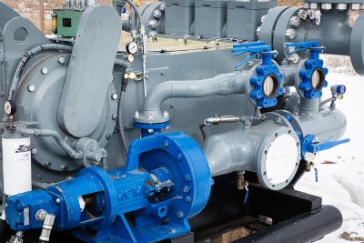
The unit comes standard with a 2" X 3" X 8 5/8" desanding and mudmixing pump. The drilling or charge pump is a choice of 3x4 mission magnum centrifugal pump or 4.5"x5" American manufacturing duplex pump for drilling most domestic wells or charging most duplex pumps.

When you access Power Zone Equipment’s websites or web portals, we may automatically (i.e., not by registration) collect non-personal data (e.g. type of Internet browser and operating system used, domain name of the website from which you came, number of visits, average time spent on the site, pages viewed). We may use this data and share it with our worldwide affiliates and related service providers to monitor the attractiveness of our websites and improve their performance or content. In this case, processing is performed on an anonymous basis and at Power Zone Equipment’s discretion.
When you access Power Zone Equipment’s websites or web portals, we may automatically (i.e., not by registration) collect non-personal data (e.g. type of Internet browser and operating system used, domain name of the website from which you came, number of visits, average time spent on the site, pages viewed). We may use this data and share it with our worldwide affiliates and related service providers to monitor the attractiveness of our websites and improve their performance or content. In this case, processing is performed on an anonymous basis and at Power Zone Equipment’s discretion.

GNSB Series Centrifugal pump is a very common device used at drilling mud solids control system. GNSB Series Centrifugal pump can be used for oil field drilling mud system, HDD and CBM drilling mud recycling system, piling and micro tunneling desanding plant. GN Solids Control is a professional manufacturer of centrifugal pump in China.
1. GNSB Series Centrifugal pump can be used as trip pump in the trip tank of the oil and gas drilling mud system. Trip tank is normally the first tank compartment inside drilling mud solids control system. The tank volume of trip tank is not big. It can be a separate smaller size tank other other tanks in the solids control system. It can also a compartment divided from shale shaker tank. Centrifugal pump size 3×2 or 4×3 are mostly used as trip tank trip pump.
2. GNSB Series Centrifugal pump can be used as feed pump for desander, desilter, mud cleaner. The pump transfer capacity should be matching the handling capacity of desander, desilter and mud cleaner. It can be a little big higher than the separation equipment, but it cannot be too much high. And the centrifugal pump transfer capacity cannot be lower than the separation equipment.
3. GNSB Series Centrifugal pump can be used as mixing pump of jet mud mixer and mixing unit. While add a T-pipe at the outlet of the mixing pump, the same pump can also be used as transfer pump.
4. GNSB Series Centrifugal pump can be used as transfer pump to transfer drilling mud or other slurries from one tank to another, or from one location to another.
All GN model centrifugal pump use tungsten carbide mechanical seal, with international famous brand Bearing. And spare parts interchangeable with most of the international Brand pump which helps customer to source spare parts easily. Open impeller design that lowers axial thrust loads, and make it easier for installation, repair and maintenance.

We are the original designers and manufacturers of the MudMaster MM420DT and MM435DT mud pumps. For over 35 years, we have built and supported the best pump packages in the industry. With over 1,000 units in service, you are assured of a quality product and after-sales support.
Standard build includes TEFC motor. “Explosion proof” motors are also available. This belt driven unit is easily adjusted and permanently aligned. The triplex piston type pump is simple, rugged and reliable. 50 Hz or 60 Hz motors are available at any common three-phase voltage input. A preset, adjustable pressure relief valve is standard equipment.
Rating is 25 US gpm (95 L) with disc type valves or 20 US gpm (76 L) with ball valves. Disc valves are intended for use with clean fluids and ball valves are suited to drilling mud solutions. The pumps are available with optional materials of construction to suit special applications.

This invention relates to apparatus useful in connection with the drilling of wells, such as oil wells, wherein a mud pump is used to circulate drilling mud under pressure through a drill string, down to and around the drill bit and out the annulus of the bore hole of the well to a mud reservoir; the apparatus of the present invention being useful for simultaneously degassing drilling mud and supercharging the mud pump.
In the drilling of deep wells, such as oil wells, it is common practice to penetrate the earth with a drill bit supported on a drill string in the bore of the well being drilled. In order to lubricate the drill bit, protect the well against blowouts, etc., it is conventional practice to circulate mud under pressure through the drill string down to and around the drill bit and up the annulus between the drill string and the bore of the well. Mud flowing from the well is passed through a suitable device such as a shaker, etc., in order to remove drill cuttings, etc., and is then delivered to a mud reservoir, such as a mud tank, for recirculation to the mud pump for pressured injection into the well.
It is also conventional practice to use a mud pump, such as a duplex or triplex mud pump comprising reciprocating pistons mounted in cylinders for pressuring the incoming drilling mud and delivering it to the well bore under pressure. The operation and construction of mud pumps is well known to those of ordinary skill in the art, as illustrated, for example, by the textbook "Mud Pump Handbook" by Samuel L. Collier (Gulf Publishing Company, Houston, Tex., 1983).
It is known, as explained in the Collier handbook, that the efficiency of a mud pump can be significantly improved by supercharging the pump; that is, by delivering drilling mud under pressure to the mud pump inlet to the cylinders containing the reciprocating pumping pistons.
It is also known to remove occluded gasses such as air, methane, etc., from drilling mud before it is delivered to the mud pump as illustrated, for example, by Burgess U.S. Pat. No. 3,973,930, Burgess U.S. Pat. No. 3,999,965 and Burgess U.S. Pat. No. 4,084,946.
Other drilling mud degassing devices are known to the art, such as those disclosed in Phillips et al. U.S. Pat. No. 4,088,457, Brown et al. U.S. Pat. No. 4,113,452, Egbert U.S. Pat. No. 4,365,977, Gowan et al. U.S. Pat. No. 4,397,659, etc.
Mud pumps used for delivering drilling mud under pressure to the bore hole of a well are conventionally of the type wherein a reciprocating piston in a cylinder is used to pressure drilling mud delivered to the cylinder for delivery to the well bore. Normally, two or three such cylinders are used, such pumps being conventionally referred to as duplex and triplex pumps. During each stroke of the piston, the piston is initially accelerated by an appropriate drive means, such as a crank shaft, from a starting position to a midcylinder position, and then decelerated to a final position within the cylinder. This constantly changing rate of motion of a reciprocating piston can result in knocking, cavitation, etc., all of which impair the efficiency of the pump. It is known to use centrifugal pumps, commonly known as superchargers, in order to deliver drilling mud to the inlet of the cylinder under pressure in order to alleviate such problems and improve the efficiency of operation of the pump.
It is undesirable to recirculate drilling mud containing occluded gases to a well bore, and therefore it is common practice to remove a significant portion of occluded gas from the drilling mud before it is recirculated to the mud pump. Normally, separate pieces of equipment that operate independently of each other are used for supercharging the mud pump and for degassing the drilling mud.
It has been discovered in accordance with the present invention that a drilling mud degasser of the type disclosed in the Burgess patents can be modified to simultaneously degas drilling mud and to supercharge the mud pump to which the degassed mud is to be delivered.
This is accomplished in accordance with the present invention through the provision of a device for simultaneously supercharging a mud pump having pistons reciprocably mounted in cylinders while degassing drilling mud to be delivered to said pistons comprising:
vacuum chamber means for continuously accelerating and centrifuging drilling mud under vacuum to thereby substantially completely remove occluded gas from the drilling mud,
a first conduit interconnecting said vacuum chamber with a drilling mud reservoir for delivering drilling mud to be degassed to said vacuum chamber means,
a first valve controlled branch conduit interconnecting said second conduit with said drilling mud reservoir for delivering drilling mud to said drilling mud reservoir when the pressure in said second conduit exceeds a predetermined value, and
a second branch conduit containing normally closed flow control means interconnecting said second conduit with said first conduit and said drilling mud reservoir operable on loss of pressure in said second conduit to permit flow of drilling mud directly from said drilling mud reservoir to said second conduit.
Referring now to the drawing, there is shown a supercharging drilling mud degasser 10 of the present invention which comprises a degassing chamber designated generally by the number 12, a power source such as an electric powered motor or a hydraulically powered motor designated generally by the number 14, a vacuum blower such as a regenerative vacuum blower, designated generally by the number 16, a gear box designated generally by the number 18, an evacuation pump designated generally by the number 20 and a drilling mud chamber designated generally by the number 22.
In accordance with this construction, there is provided a drilling mud degasser of the type shown in Burgess U.S. Pat. No. 4,084,946, housed in a cylindrical pressure vessel 24. The motor 14 is supported on vacuum blower 16 which, in turn, is supported by vacuum motor support 26 and vacuum blower brackets 28. To facilitate movement of the degasser 10, motor handling brackets 30 may be provided on the top of the motor 14 to which the hook of a crane or other appropriate means (not shown) may be attached.
Drilling mud pump impeller 42 is fixed to the centrifuge tube 40 for rotation therewith within the housing 46 of drilling mud evacuation pump 20. Cross braces 48 mounted in the cylindrical vessel 24 support lower stops 50 and upper stops 52 for an annular float 56 that surrounds the slots of the centrifuge tube 40 and partially closes them, such that the free area of the slots will be determined by the relative position of the annular float 56.
A drilling mud inlet 60 is connected to the bottom of the housing 46 for the evacuation pump 20 for the delivery of degassed drilling mud thereto. Drilling mud is delivered to the slotted centrifuge tube 40 by an inlet conduit 62 which preferably terminates inside the housing 46 for the evacuation pump 20. The top of the inlet line 62 is spaced from the bottom of the slotted centrifuge tube 40 so that the rotating centrifuge tube 40 can rotate freely without bearing upon the top of the inlet line 62. The resultant "controlled seepage" of fluid from the inlet tube 62 into the evacuation pump 20 provides a low pressure area for high effeciency scanvenging of occluded gases. Also, there is no need for bearings and seals at the bottom of the slotted centrifuge tube 40.
With this construction there is also provided an outlet line or conduit 66 connected with the discharge side of the evacuation pump 20 and extending through the wall of the cylinder 24 for connection with a suitable first conduit 68 leading, for example, to a triplex pump 70 for injecting drilling mud under pressure into a well penetrating a subterranean formation in order to lubricate the drill bit, protect the well against blow outs, etc., it is conventional practice to circulate mud under pressure through the drill string down to and around the drill bit and up the annulus beteen the drill string and the bore of the well. Mud flowing from the well is passed through a suitable device such as a shaker, etc. (not shown) in order to remove drill cuttings, etc., and is then delivered to a mud reservoir, such as a mud tank 84, for recirculation to the mud pump 70 in the manner described herein for pressured injection into the well.
The first conduit 68 may comprise, for example, a connecting pipe 72 interconnecting the outlet line 66 with the flexible hose 74 which, in turn, is connected to a mud pump inlet line 76. The flexible hose 74, which is provided for ease in alignment, may be secured to the connecting pipe 72 by a clamp 78 of any suitable construction and to the mud pump inlet line 76 by a clamp 80 of any suitable construction.
A second conduit 82 interconnects a drilling mud reservoir such as a mud tank 84 with the inlet conduit 62 leading to the slotted centrifuge tube 40 for the degasser 10.
Preferably, the second conduit 82 is provided with valve means such as a butterfly valve 86 which may be used to close the second conduit 82 when both the drilling mud degasser 10 and the mud pump 70 are to be idled for any appreciable time.
A first branch conduit 88 interconnects the first conduit 68 with the mud tank 84 and contains pressure sensitive control means such as a spring biased relief valve 90 in order to permit drilling mud to recycle from the first conduit 68 to the mud tank 84 when the pressure in the first conduit 68 exceeds a predetermined value.
A second branch conduit 92 interconnects the first conduit 68 with the inlet conduit 62 and the second conduit 82. The second branch conduit 92 contains normally closed flow control means such as a check valve 94 to permit flow of drilling mud directly from the mud tank 84 to the mud pump 70 if the pressure in the first conduit 68 falls below a predetermined value.
During drilling operations, rotation of an appropriate vacuum blower such as a regenerative vacuum blower by the drive shaft 32 for the motor 14 will generate a vacuum in the degassing chamber 12 such that drilling mud sprayed from the slots in the centrifuge tube 40 will tend to impact upon the inner sides of the degassing chamber 12 thereby initiating degassing of the drilling mud fed through the inlet line 62. Rotation of the centrifuge tube 40 will impart upward accelerating rotary motion to partially degassed drilling mud delivered thereto through the line 62 and the resultant spraying of the thus centrifuged drilling mud through the slots in the centrifuge tube 40 will result in a sheet of drilling mud being sprayed onto and impacting on the inner walls of the degassing chamber 12 to thus substantially complete the removal of gas from the drilling mud. The thus degassed drilling mud will flow downwardly past cross braces 48 and into inlet 60 leading through the housing 46 of the evacuation pump 20 where the impeller 42 will repressure the now degassed drilling mud for discharge through the outlet line 66 which is interconnected with a triplex pump 70 by first conduit 68 for supercharging the pump 70, which further pressures the degassed drilling mud for injection into a well bore penetrating a subterranean formation.
In order to prevent the entrainment of drilling mud droplets in the gases withdrawn through the gas evacuation suction pipe 98, a splatter plate 100 is provided in the degassing chamber 12 and a combination of a foam separation impeller 36 with a splatter disk 102 is provided adjacent the top of the degassing chamber 12 so that gas liberated in the vacuum chamber must follow a sinuous path arriving at the upper chamber gas evacuation suction pipe 98.
In accordance with the present invention, the motor 14 is operated such that drilling mud delivered to the first conduit 68 will be at a predetermined appropriate supercharging pressure for the mud pump 70, (e.g. a pressure of about 20 to 30 psig).
The pressure sensitive control means, such as a spring biased relief valve 90, is set to open at a predetermined pressure about 5 to 10 psi higher than the desired pressure in the first conduit 68 so that, if the indicated pressure limit is exceeded, the pressure relief valve 90 will open in order to permit drilling mud to recycle to the mud tank 84.
This will happen if the mud pump 70 malfunctions and also when the mud pump 70 is turned off, as will happen from time to time. For example, it is necessary to turn off the mud pump 70 during drilling operations when a new stand of drill pipe is to be added to the drill string. It is also necessary to turn off the mud pump 70 when the drill string is being withdrawn from the well bore in order to replace the drill bit, while well logging operations are in progress, if it is necessary to "fish" for a piece of equipment lost down the hole, etc. However, if the drilling mud in the mud tank 84 is permitted to remain quiescent for more than a limited period of time, the drilling mud may start to gel and/or to stratify. This problem is conventionally avoided by providing a separate agitator (not shown) for the mud tank 84 in order to stir the drilling mud when the mud pump 70 is idle. However, through the provision of the present invention, there is no need for a separate agitator for the mud tank 84 because recirculation of drilling mud through the first branch conduit 88 will impart a "roiling" motion or agitation to the drilling mud in mud tank 84 to inhibit gelling and/or stratification of the drilling mud while the mud pump 70 is idle.
Loss of pressure in the first conduit 68 can occur in the event of malfunction of the degasser 10 or in the event it is desired to shut the degasser 10 down for a limited period of time. In this event, drilling mud flows directly from the mud tank 84 through the second conduit 82, the second branch conduit 92 and the flexible hose 74 to the mud pump 70 so that the mud pum 70 is not "starved" for drilling mud to be injected into the well.

The drilling industry has roots dating back to the Han Dynasty in China. Improvements in rig power and equipment design have allowed for many advances in the way crude oil and natural gas are extracted from the ground. Diesel/electric oil drilling rigs can now drill wells more than 4 miles in depth. Drilling fluid, also called drilling mud, is used to help transfer the dirt or drill cuttings from the action of the drilling bit back to the surface for disposal. Drill cuttings can vary in shape and size depending on the formation or design of the drill bit used in the process.
Watch the video below to see how the EDDY Pump outperforms traditional pumps when it comes to high solids and high viscosity materials commonly found on oil rigs.
The fluid is charged into high-pressure mud pumps which pump the drilling mud down the drill string and out through the bit nozzles cleaning the hole and lubricating the drill bit so the bit can cut efficiently through the formation. The bit is cooled by the fluid and moves up the space between the pipe and the hole which is called the annulus. The fluid imparts a thin, tough layer on the inside of the hole to protect against fluid loss which can cause differential sticking.
The fluid rises through the blowout preventers and down the flowline to the shale shakers. Shale shakers are equipped with fine screens that separate drill cutting particles as fine as 50-74 microns. Table salt is around 100 microns, so these are fine cuttings that are deposited into the half-round or cuttings catch tank. The drilling fluid is further cleaned with the hydro-cyclones and centrifuges and is pumped back to the mixing area of the mud tanks where the process repeats.
The drill cuttings contain a layer of drilling fluid on the surface of the cuttings. As the size of the drill cuttings gets smaller the surface area expands exponentially which can cause rheological property problems with the fluid. The fluid will dehydrate and may become too thick or viscous to pump so solids control and dilution are important to the entire drilling process.
One of the most expensive and troubling issues with drilling operations is the handling, processing, and circulation of drilling mud along with disposing of the unwanted drill cuttings. The drilling cuttings deposited in the half round tank and are typically removed with an excavator that must move the contents of the waste bin or roll-off box. The excavators are usually rented for this duty and the equipment charges can range from $200-300/day. Add in the cost for the day and night manpower and the real cost for a single excavator can be as much as $1800/day.
Offshore drilling rigs follow a similar process in which the mud is loaded into empty drums and held on the oil platform. When a certain number of filled drums is met, the drums are then loaded onto barges or vessels which take the drilling mud to the shore to unload and dispose of.
Oil field drilling operations produce a tremendous volume of drill cuttings that need both removal and management. In most cases, the site managers also need to separate the cuttings from the drilling fluids so they can reuse the fluids. Storing the cuttings provides a free source of stable fill material for finished wells, while other companies choose to send them off to specialty landfills. Regardless of the final destination or use for the cuttings, drilling and dredging operations must have the right high solids slurry pumps to move them for transport, storage, or on-site processing. Exploring the differences in the various drilling fluids, cutting complications, and processing options will reveal why the EDDY Pump is the best fit for the job.
The Eddy Pump is designed to move slurry with solid content as high as 70-80 % depending on the material. This is an ideal application for pumping drill cuttings. Drill cuttings from the primary shakers are typically 50% solids and 50% liquids. The Eddy Pump moves these fluids efficiently and because of the large volute chamber and the design of the geometric rotor, there is very little wear on the pump, ensuring long life and greatly reduced maintenance cost for the lifetime of the pump.
plumbed to sweep the bottom of the collection tank and the pump is recessed into a sump allowing for a relatively clean tank when the solids are removed. The Eddy Pump is sized to load a roll-off box in 10-12 minutes. The benefit is cuttings handling is quicker, easier, safer, and allows for pre-planning loading where the labor of the solids control technician is not monopolized by loading cuttings. Here, in the below image, we’re loading 4 waste roll-off bins which will allow the safe removal of cuttings without fear of the half-round catch tank running over.
Mud cleaning systems such as mud shaker pumps and bentonite slurry pumps move the material over screens and through dryers and centrifuges to retrieve even the finest bits of stone and silt. However, the pump operators must still get the raw slurry to the drill cuttings treatment area with a power main pump. Slurry pumps designed around the power of an Eddy current offer the best performance for transferring cuttings throughout a treatment system.
Options vary depending on whether the company plans to handle drill cuttings treatment on-site or transport the materials to a remote landfill or processing facility. If the plan is to deposit the cuttings in a landfill or a long-term storage container, it’s best to invest in a pump capable of depositing the material directly into transport vehicles. Most dredging operations rely on multiple expensive vacuum trucks, secondary pumps, and extra pieces of equipment.
Using an EDDY Pump will allow a project to eliminate the need for excavators/operators to load drill cuttings, substantially lowering both labor and heavy equipment costs. The EDDY Pump also allows a company to eliminate vacuum trucks once used for cleaning the mud system for displacing fluids. Since the pump transfers muds of all types at constant pressure and velocity throughout a system of practically any size, there’s little need for extra equipment for manual transfer or clean up on the dredge site.
The EDDY Pump can fill up a truck in only 10 minutes (compared to an hour) by using a mechanical means such as an excavator. For this reason, most companies can afford one piece of equipment that can replace half a dozen other units.
This application for the Eddy Pump has the potential to revolutionize the drilling industry. Moving the excavator out of the “back yard” (the area behind the rig from the living quarters) will make cuttings handling a breeze. Trucking can be easier scheduled during daylight hours saving on overtime and incidences of fatigued driving. Rig-site forklifts can move the roll-off boxes out of the staging area and into the pump loading area. The operator can save money on excavators rental, damages, and keep the technician operating the solids control equipment.
The EDDY Pump is ideal for drilling mud pump applications and can be connected directly onto the drilling rigs to pump the drilling mud at distances over a mile for disposal. This eliminates the need for costly vacuum trucks and also the manpower needed to mechanically move the drilling mud. The reasons why the EDDY Pump is capable of moving the drilling mud is due to the hydrodynamic principle that the pump creates, which is similar to the EDDY current of a tornado. This tornado motion allows for the higher viscosity and specific gravity pumping ability. This along with the large tolerance between the volute and the rotor allows for large objects like rock cuttings to pass through the pump without obstruction. The large tolerance of the EDDY Pump also enables the pump to last many times longer than centrifugal pumps without the need for extended downtime or replacement parts. The EDDY Pump is the lowest total life cycle pump on the market.


 8613371530291