
mud pump charging system supplier
AfghanistanAlbaniaAlgeriaAmerican SamoaAndorraAngolaAnguillaAntarcticaAntigua and BarbudaArgentinaArmeniaArubaAustraliaAustriaAzerbaijanBahamasBahrainBangladeshBarbadosBelarusBelgiumBelizeBeninBermudaBhutanBoliviaBonaire, Sint Eustatius and SabaBosnia and HerzegovinaBotswanaBouvet IslandBrazilBritish Indian Ocean TerritoryBrunei DarussalamBulgariaBurkina FasoBurundiCabo VerdeCambodiaCameroonCanadaCayman IslandsCentral African RepublicChadChileChinaChristmas IslandCocos IslandsColombiaComorosCongoCongo, Democratic Republic of theCook IslandsCosta RicaCroatiaCubaCuraçaoCyprusCzechiaCôte d"IvoireDenmarkDjiboutiDominicaDominican RepublicEcuadorEgyptEl SalvadorEquatorial GuineaEritreaEstoniaEswatiniEthiopiaFalkland IslandsFaroe IslandsFijiFinlandFranceFrench GuianaFrench PolynesiaFrench Southern TerritoriesGabonGambiaGeorgiaGermanyGhanaGibraltarGreeceGreenlandGrenadaGuadeloupeGuamGuatemalaGuernseyGuineaGuinea-BissauGuyanaHaitiHeard Island and McDonald IslandsHoly SeeHondurasHong KongHungaryIcelandIndiaIndonesiaIranIraqIrelandIsle of ManIsraelItalyJamaicaJapanJerseyJordanKazakhstanKenyaKiribatiKorea, Democratic People"s Republic ofKorea, Republic ofKuwaitKyrgyzstanLao People"s Democratic RepublicLatviaLebanonLesothoLiberiaLibyaLiechtensteinLithuaniaLuxembourgMacaoMadagascarMalawiMalaysiaMaldivesMaliMaltaMarshall IslandsMartiniqueMauritaniaMauritiusMayotteMexicoMicronesiaMoldovaMonacoMongoliaMontenegroMontserratMoroccoMozambiqueMyanmarNamibiaNauruNepalNetherlandsNew CaledoniaNew ZealandNicaraguaNigerNigeriaNiueNorfolk IslandNorth MacedoniaNorthern Mariana IslandsNorwayOmanPakistanPalauPalestine, State ofPanamaPapua New GuineaParaguayPeruPhilippinesPitcairnPolandPortugalPuerto RicoQatarRomaniaRussian FederationRwandaRéunionSaint BarthélemySaint Helena, Ascension and Tristan da CunhaSaint Kitts and NevisSaint LuciaSaint MartinSaint Pierre and MiquelonSaint Vincent and the GrenadinesSamoaSan MarinoSao Tome and PrincipeSaudi ArabiaSenegalSerbiaSeychellesSierra LeoneSingaporeSint MaartenSlovakiaSloveniaSolomon IslandsSomaliaSouth AfricaSouth Georgia and the South Sandwich IslandsSouth SudanSpainSri LankaSudanSurinameSvalbard and Jan MayenSwedenSwitzerlandSyria Arab RepublicTaiwanTajikistanTanzania, the United Republic ofThailandTimor-LesteTogoTokelauTongaTrinidad and TobagoTunisiaTurkmenistanTurks and Caicos IslandsTuvaluTürkiyeUS Minor Outlying IslandsUgandaUkraineUnited Arab EmiratesUnited KingdomUnited StatesUruguayUzbekistanVanuatuVenezuelaViet NamVirgin Islands, BritishVirgin Islands, U.S.Wallis and FutunaWestern SaharaYemenZambiaZimbabweÅland Islands

When you access Power Zone Equipment’s websites or web portals, we may automatically (i.e., not by registration) collect non-personal data (e.g. type of Internet browser and operating system used, domain name of the website from which you came, number of visits, average time spent on the site, pages viewed). We may use this data and share it with our worldwide affiliates and related service providers to monitor the attractiveness of our websites and improve their performance or content. In this case, processing is performed on an anonymous basis and at Power Zone Equipment’s discretion.
A well-placed suction stabilizer can also prevent pump chatter. Pump chatter occurs when energy is exchanged between the quick opening and closing of the reciprocating pump’s valves and the hammer effect from the centrifugal pump. Pump isolation with suction stabilizers is achieved when the charge pumps are isolated from reciprocating pumps and vice versa. The results are a smooth flow of pumped media devoid of agitating energies present in the pumped fluid.
Suction stabilizer units can mitigate most of the challenges related to pulsations or pressure surges, even in the most complex piping conditions. The resulting benefits prevent expensive unplanned downtime and decrease costs and inconvenience associated with system replacements and repairs.

We are the original designers and manufacturers of the MudMaster MM420DT and MM435DT mud pumps. For over 35 years, we have built and supported the best pump packages in the industry. With over 1,000 units in service, you are assured of a quality product and after-sales support.
Standard build includes TEFC motor. “Explosion proof” motors are also available. This belt driven unit is easily adjusted and permanently aligned. The triplex piston type pump is simple, rugged and reliable. 50 Hz or 60 Hz motors are available at any common three-phase voltage input. A preset, adjustable pressure relief valve is standard equipment.
Rating is 25 US gpm (95 L) with disc type valves or 20 US gpm (76 L) with ball valves. Disc valves are intended for use with clean fluids and ball valves are suited to drilling mud solutions. The pumps are available with optional materials of construction to suit special applications.

The drilling industry has roots dating back to the Han Dynasty in China. Improvements in rig power and equipment design have allowed for many advances in the way crude oil and natural gas are extracted from the ground. Diesel/electric oil drilling rigs can now drill wells more than 4 miles in depth. Drilling fluid, also called drilling mud, is used to help transfer the dirt or drill cuttings from the action of the drilling bit back to the surface for disposal. Drill cuttings can vary in shape and size depending on the formation or design of the drill bit used in the process.
Watch the video below to see how the EDDY Pump outperforms traditional pumps when it comes to high solids and high viscosity materials commonly found on oil rigs.
The fluid is charged into high-pressure mud pumps which pump the drilling mud down the drill string and out through the bit nozzles cleaning the hole and lubricating the drill bit so the bit can cut efficiently through the formation. The bit is cooled by the fluid and moves up the space between the pipe and the hole which is called the annulus. The fluid imparts a thin, tough layer on the inside of the hole to protect against fluid loss which can cause differential sticking.
The fluid rises through the blowout preventers and down the flowline to the shale shakers. Shale shakers are equipped with fine screens that separate drill cutting particles as fine as 50-74 microns. Table salt is around 100 microns, so these are fine cuttings that are deposited into the half-round or cuttings catch tank. The drilling fluid is further cleaned with the hydro-cyclones and centrifuges and is pumped back to the mixing area of the mud tanks where the process repeats.
The drill cuttings contain a layer of drilling fluid on the surface of the cuttings. As the size of the drill cuttings gets smaller the surface area expands exponentially which can cause rheological property problems with the fluid. The fluid will dehydrate and may become too thick or viscous to pump so solids control and dilution are important to the entire drilling process.
One of the most expensive and troubling issues with drilling operations is the handling, processing, and circulation of drilling mud along with disposing of the unwanted drill cuttings. The drilling cuttings deposited in the half round tank and are typically removed with an excavator that must move the contents of the waste bin or roll-off box. The excavators are usually rented for this duty and the equipment charges can range from $200-300/day. Add in the cost for the day and night manpower and the real cost for a single excavator can be as much as $1800/day.
Offshore drilling rigs follow a similar process in which the mud is loaded into empty drums and held on the oil platform. When a certain number of filled drums is met, the drums are then loaded onto barges or vessels which take the drilling mud to the shore to unload and dispose of.
Oil field drilling operations produce a tremendous volume of drill cuttings that need both removal and management. In most cases, the site managers also need to separate the cuttings from the drilling fluids so they can reuse the fluids. Storing the cuttings provides a free source of stable fill material for finished wells, while other companies choose to send them off to specialty landfills. Regardless of the final destination or use for the cuttings, drilling and dredging operations must have the right high solids slurry pumps to move them for transport, storage, or on-site processing. Exploring the differences in the various drilling fluids, cutting complications, and processing options will reveal why the EDDY Pump is the best fit for the job.
The Eddy Pump is designed to move slurry with solid content as high as 70-80 % depending on the material. This is an ideal application for pumping drill cuttings. Drill cuttings from the primary shakers are typically 50% solids and 50% liquids. The Eddy Pump moves these fluids efficiently and because of the large volute chamber and the design of the geometric rotor, there is very little wear on the pump, ensuring long life and greatly reduced maintenance cost for the lifetime of the pump.
plumbed to sweep the bottom of the collection tank and the pump is recessed into a sump allowing for a relatively clean tank when the solids are removed. The Eddy Pump is sized to load a roll-off box in 10-12 minutes. The benefit is cuttings handling is quicker, easier, safer, and allows for pre-planning loading where the labor of the solids control technician is not monopolized by loading cuttings. Here, in the below image, we’re loading 4 waste roll-off bins which will allow the safe removal of cuttings without fear of the half-round catch tank running over.
Mud cleaning systems such as mud shaker pumps and bentonite slurry pumps move the material over screens and through dryers and centrifuges to retrieve even the finest bits of stone and silt. However, the pump operators must still get the raw slurry to the drill cuttings treatment area with a power main pump. Slurry pumps designed around the power of an Eddy current offer the best performance for transferring cuttings throughout a treatment system.
Options vary depending on whether the company plans to handle drill cuttings treatment on-site or transport the materials to a remote landfill or processing facility. If the plan is to deposit the cuttings in a landfill or a long-term storage container, it’s best to invest in a pump capable of depositing the material directly into transport vehicles. Most dredging operations rely on multiple expensive vacuum trucks, secondary pumps, and extra pieces of equipment.
Using an EDDY Pump will allow a project to eliminate the need for excavators/operators to load drill cuttings, substantially lowering both labor and heavy equipment costs. The EDDY Pump also allows a company to eliminate vacuum trucks once used for cleaning the mud system for displacing fluids. Since the pump transfers muds of all types at constant pressure and velocity throughout a system of practically any size, there’s little need for extra equipment for manual transfer or clean up on the dredge site.
The EDDY Pump can fill up a truck in only 10 minutes (compared to an hour) by using a mechanical means such as an excavator. For this reason, most companies can afford one piece of equipment that can replace half a dozen other units.
This application for the Eddy Pump has the potential to revolutionize the drilling industry. Moving the excavator out of the “back yard” (the area behind the rig from the living quarters) will make cuttings handling a breeze. Trucking can be easier scheduled during daylight hours saving on overtime and incidences of fatigued driving. Rig-site forklifts can move the roll-off boxes out of the staging area and into the pump loading area. The operator can save money on excavators rental, damages, and keep the technician operating the solids control equipment.
The EDDY Pump is ideal for drilling mud pump applications and can be connected directly onto the drilling rigs to pump the drilling mud at distances over a mile for disposal. This eliminates the need for costly vacuum trucks and also the manpower needed to mechanically move the drilling mud. The reasons why the EDDY Pump is capable of moving the drilling mud is due to the hydrodynamic principle that the pump creates, which is similar to the EDDY current of a tornado. This tornado motion allows for the higher viscosity and specific gravity pumping ability. This along with the large tolerance between the volute and the rotor allows for large objects like rock cuttings to pass through the pump without obstruction. The large tolerance of the EDDY Pump also enables the pump to last many times longer than centrifugal pumps without the need for extended downtime or replacement parts. The EDDY Pump is the lowest total life cycle pump on the market.

In addition to selecting the proper suction pipe diameter and having adequate NPSHA, the submergence level and suction pipe configuration must be considered. Submergence level is the depth of the suction pipe inlet below the liquid surface. If an inadequate submergence level exists, an air vortex will form that extends from the liquid surface to the inlet of the suction pipe. This will introduce air into the system, resulting in either turbulent flow patterns or vapor locking of the pump. Amount of submergence required varies with velocity of the fluid. Fluid velocity is controlled by flow rate and pipe diameter. Refer to Figure 1. to determine submergence required based on fluid velocity (fluid velocity can be found in Friction Loss (Centrifugal Pumps Velocity Measured), in the column ‘‘V (ft/sec)’’).
If a system utilizes a 6-inch suction line with a flow rate of 600 gpm, suction-line velocities will be 6.6 fps and the line will therefore require approximately 3.5 feet of liquid surface above the suction-line entrance. Once the submergence level drops below 3.5 feet, an air vortex will form, causing air to enter the pump suction, resulting in a turbulent flow pattern and/or vapor lock.
to 8 inches would result in an insufficient line velocity of 3.85 ft/sec. However, most systems will require the tank to have the ability to drain lower than 3.5 feet. One solution is to install a baffle plate over the suction pipe. If a 14-inch baffle plate is installed, fluid velocities around the edge of the plate are only 1.25 ft/sec, which would allow the tank to be drained to approximately 1 foot above the suction pipe entrance. Refer to Figure 2. for an illustrated view of a baffle plate.
In addition to proper line size and submergence level, a suction pipe should slope gradually upward from the source to the pump suction. This prevents air traps within the suction line. There should be a straight run prior to the pump entrance of at least two pipe diameters in length to reduce turbulence. A smooth-flowing valve should be installed in the suction line that will allow the pump to be isolated for maintenance and inspection. If a suction hose is used in lieu of hard piping, the hose must be noncollapsing. Refer to Figures 3 and 4 for examples of accepted piping practices.
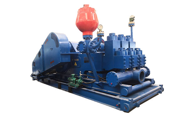
Triplex mud pumps are often operated at speeds at which head in the suction tank is insufficient to maintain fluid against the piston face during the filling stroke. If fluid does not remain against the face, air is sucked in from behind the piston, causing a fluid void. If a void is formed, the piston strikes the fluid when the piston reverses direction during the pressure stroke. This causes a shock load that damages the triplex power end and fluid end and lowers expendable parts life. Supercharging pumps are used to accelerate fluid in the suction line of a triplex mud pump during the filling stroke, allowing fluid to maintain pace with the piston. A properly sized supercharging pump will accelerate fluid so that fluid voids and shock loads do not occur.
Triplex mud pumps normally have shock loads at speeds greater than 60 strokes per minute (spm) (when not supercharged). Without proper equipment, this would go unnoticed until the pump exceeded 80 strokes per minute, but meanwhile the shock load is damaging the pump. Supercharging requires an oversized pump with wide impellers to adequately react to rapid changes in flow required by the triplex mud pump. When sizing a centrifugal pump for a mud pump supercharging application, the pump should be sized for 1½ times the required flow rate. Therefore, if the triplex mud pump maximum flow rate is 600 gpm, the centrifugal pump should be sized for 900 gpm. High-speed piston and plunger pumps that stroke above 200 spm should be designed with a supercharging pump that produces 1¾ to 2 times the required flow rate.
Supercharging is one of the few applications in which the centrifugal pump does not have steady flow. The flow pulsates. Small impellers operating at 1750 rpm have a tendency to slip through the fluid when acceleration is needed. This is similar to car tires slipping on wet pavement. Even though it sometimes appears that the small impeller running at 1750 rpm is providing enough head, shock loading may be occurring. Supercharging pumps should have larger impellers running at either 1150 (60 cycles) or 1450 rpm (50 cycles) and should normally be sized to produce 85 feet of head at the triplex suction inlet. Supercharging pumps should be located as close to the supply tank as possible. Mounting supercharging pumps near the triplex and away from the supply tank transfers suction problems from the triplex to the centrifugal pump. If the centrifugal pump does not have a favorable supply with short suction run, it will have an insufficient supply to accelerate fluid.
Piping for supercharging pumps and triplex pump suctions should be oversized for the flow rate. Pipe should be sized so the change in line velocity during pulsations will not be over 1.5 ft/sec during the change from low flow rate to high flow rate during the triplex pulsation cycles.
Since the change in line velocity in 6-inch pipe is less than 1.5 ft/sec, this pipe size can be used for supercharging a triplex with an average flow of 600 gpm.
There are times when a single centrifugal pump will not meet the head requirements of an application. Two pumps can be operated in series to achieve the desired discharge head, in which the discharge of one pump feeds the suction of the second pump. The second pump boosts the head produced by the first. Therefore, if an application required 2900 gpm at 200 feet of head, one option would be to run two 10×8×14 pumps in series. Each pump could be configured with a 13-inch impeller to produce 2900 gpm at 100 feet of head. When operated in series, the pumps would produce 2900 gpm at 200 feet of head.
This type of configuration is most commonly used for extremely long discharge runs. When running pumps in series, it is important not to exceed flange safety ratings. Additionally, it is not required to place pumps within close proximity of each other. If an application had a 6-mile discharge line the first pump could be located at the supply source and the second pump could be located 3 miles away.
exists that requires high volume and low head and volume required is greater than can be produced by a single pump, two pumps are sometimes used in a parallel configuration to meet the demand. Two pumps that produce the same TDH can be configured so that each pump has an individual suction but both pumps feed into the same discharge line. If the pumps are identical, head in the discharge line is equal to that of the pumps, but the volume is double what a single pump can produce. However, two centrifugal pumps will never have the exact same discharge head, and as wear occurs one pump will produce less head than the other and the stronger pump will overpower the weaker pump and force fluid to backflow into the weaker pump. For this reason, parallel operation is not normally recommended.
Two pumps can be configured in parallel but only one pump is operated at a time, thus providing a primary and a backup pump. The two pumps are separated by a valve in each discharge line that prevents one pump from pumping through the other. This type of configuration is perfectly acceptable and, in crucial applications, encouraged.

Mud cleaning systems are critical in the drilling process, as they protect the system components by lowering the solids/sand content in the drilling fluid. Cleaner fluid means much longer expendable life in the entire mud cleaning and pumping system. Lower sand content also allows the drilling fluid to carry cuttings from the bore more efficiently, making for a better bore hole and a higher rate of penetration. In addition to helping alleviate environmental mud disposal concerns, reclaiming and recycling also allows for substantial mud cost savings.
There are three main types of systems — integral trailer, skid-mounted and trailer-mounted. Skid mounted allows for transporting through very swampy and difficult terrain, as you could drag it behind a dozer or excavator to your needed work area. Integral trailer designs allows for a more compact, intended design for maximum efficiency and ease of transport.
Any properly designed and sized mud system that is operated and maintained according to the manufacturers recommended procedures and maintenance schedules, should keep your sand content at or below ¼ of 1 percent. If you are not able to keep your sand content at or below ¼ of 1 percent, expendable life will greatly diminish along with the life span of system components and other items such as mud motors.
Screen type and mesh selection are crucial to fine tuning your mud system and allows for effective screening and longer screen life. Most manufacturers include a standard set of screens that are good for an all-around starting point. Keeping a good selection of assorted mesh screens is advised, as different soil conditions dictate different mesh. You want to run the finest mesh possible, without “blinding” the screens (plugging the screen openings with solids). Screens should be maintained during operations by rinsing periodically, and handled with care. They may be easily torn by rough or careless handling, or by having items dropped or set on them.
Most systems on the market have two or three compartment tanks, depending upon the number of cleaning stages. Proper tank design should allow fluid to overflow back to the previous cleaning stage tank in case of suspended out-flow from the system. Tank volume size should be properly matched to the systems overall cleaning volume capacities.
Ideally, the applicable mud system will utilize 5-in. desilter cones, which separate solids 15 to 25 microns in size, and 10-in. desander cones, which separate solids 40 to 50 microns in size. The size and quantity of cones needed on a system depend upon the overall rated volume of the mud system. The 5-in. cones can process 80 gpm each, and 10-in. cones can process 500 gpm each. There are other sizes of cones on the market, but we feel this gives us the best volume and micron size separation.
Centrifugal pumps that are driven by electric motors are responsible for moving the drilling fluids to various areas of the system within the cleaning process. Pumps and motors should both be sized correctly to adequately handle the systems volume needs. The centrifugal pumps may feature either mechanical seals or rope packing, depending upon the pump type. Mechanical seals are relatively maintenance free, but rope packing requires proper attention. Rope style packing allows some fluid “leakage” from the packing area. Do not tighten the packing housing down to stop the leaking completely, or seal and shaft damage will occur. You should always maintain a slow drip when using rope type packing.
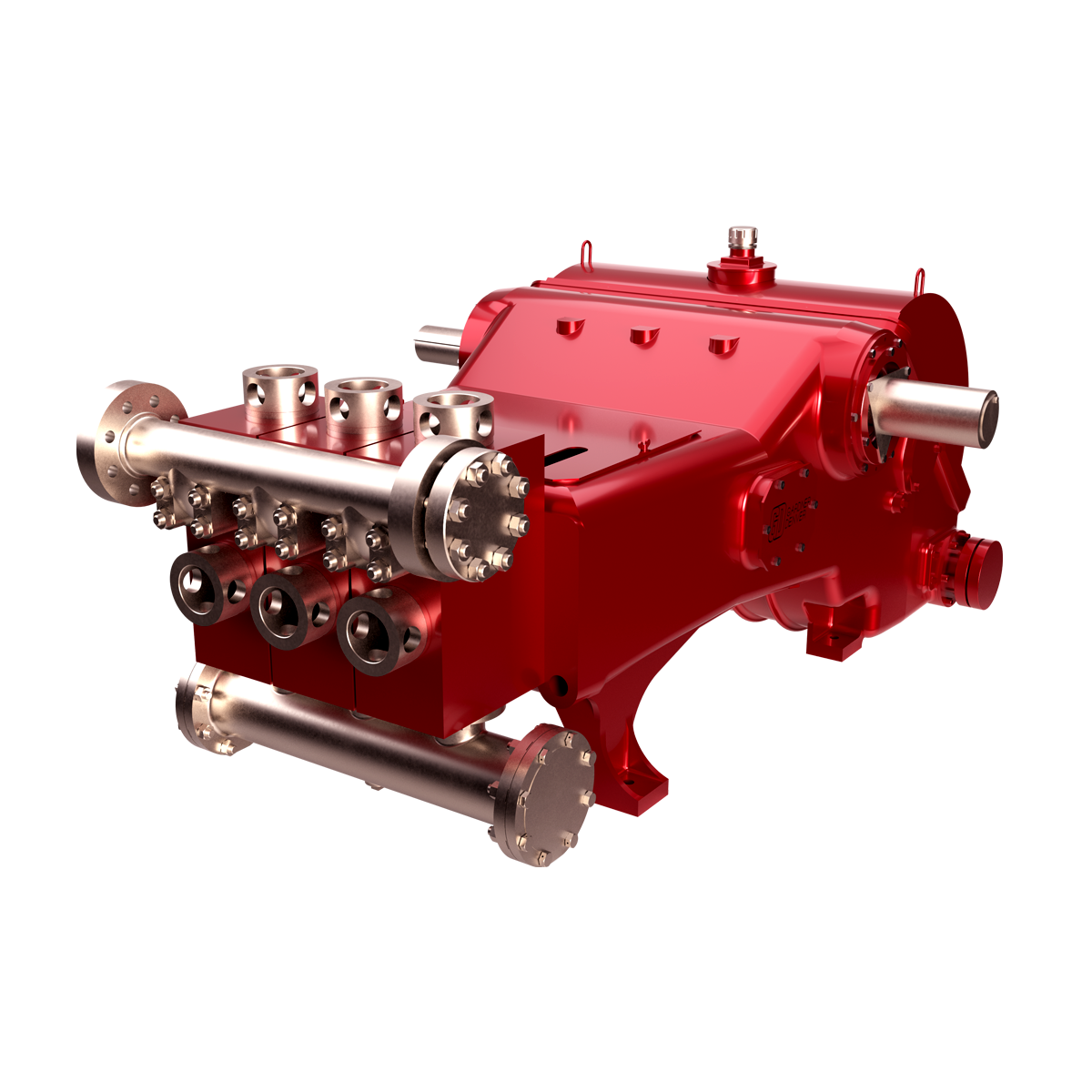
Hydraulic cylinder is forged of alloy steel. Three cylinders of one pump are interchangeable with each other. According to customers’ special requirements, to enhance the anti-corrosion performance, the surface of the hydraulic cylinder is supposed to be processed with chemical plating nickel. Pulsation dampener, shear relief valve and discharge strainer are separately mounted on the outlet.
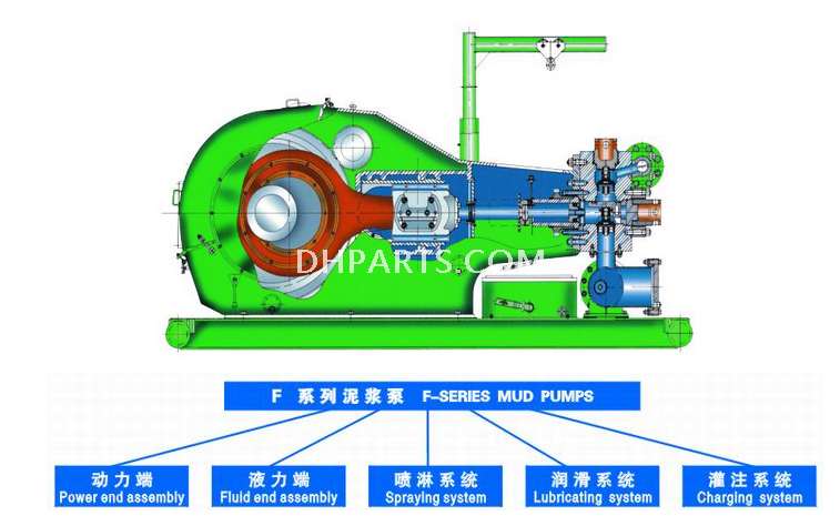
This system is consisted of spray pump, cooling water tank and spray pipelines with the function of the necessary cooling and splashing to liners and pistons to prolong their lifetime.
The splashing pump is the centrifugal pump which can be driven by the belt mounted on the end of input shaft, or can be individually driven by a motor with water as the cooling and lubrication media.
The combination of forced lubrication and splashing lubrication is used for the power end. For the purpose of forced lubrication, the gear oil pump located at the oil tank feeds compressed oil to crossheads, extension rods and bearings respectively via the lubrication pipe lines. More ever, the operation situation of the gear oil pump can be observed by the manometer embedded in the after body of mud pumps.
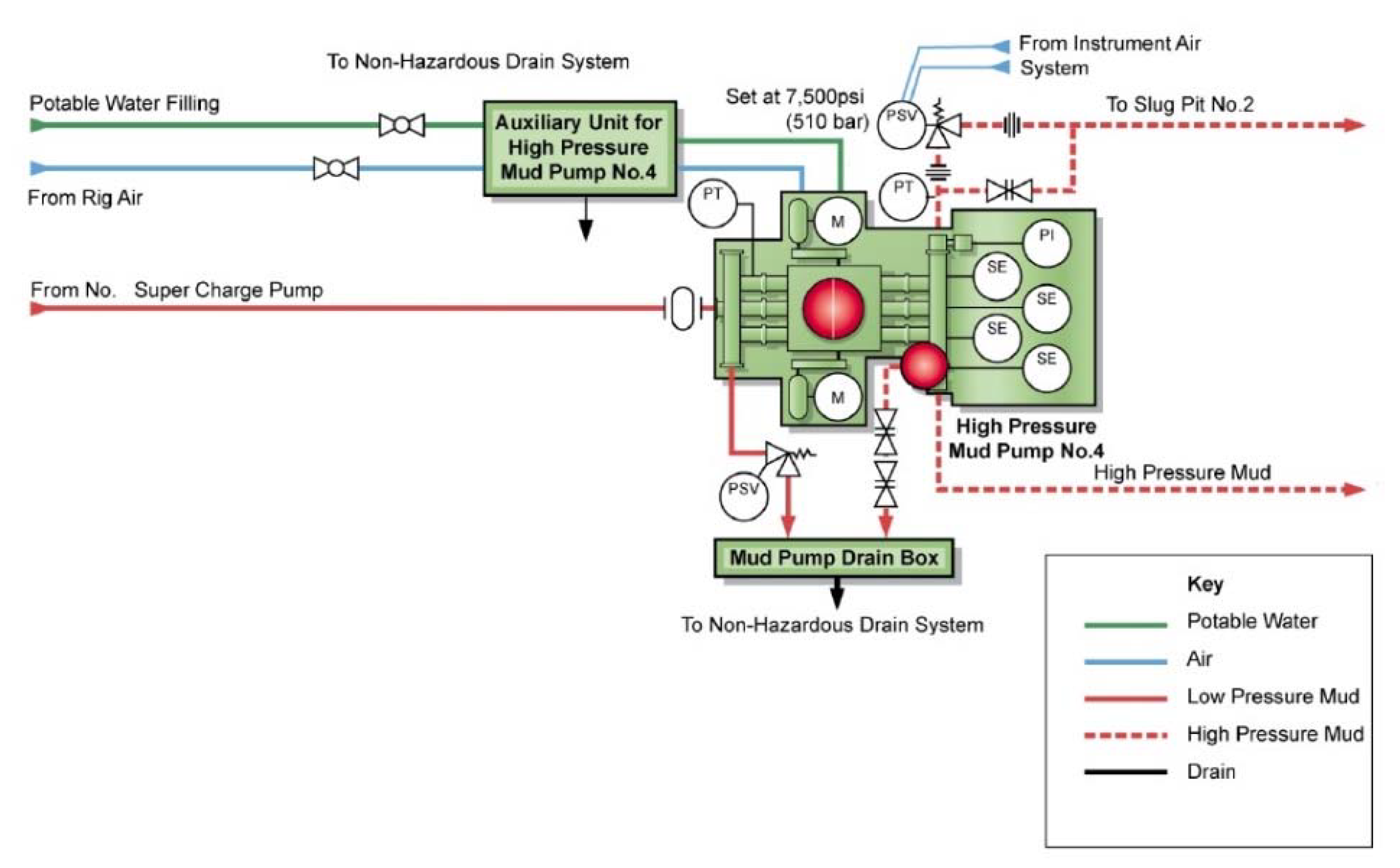
Each mud pump can be equipped with one charging pump to avoid air blocking caused by low pressure at the suction inlet. The spray system is driven by a special motor which is installed on the suction pipe assembly. To reduce the total power supply of drilling rigs, driving shaft is employed to drive the spray pump as well.
Mud centrifugal pumps are mainly design for solids control circulating system of oilfield drill rig. It can be used to provide drilling liquid with a certain discharge capacity and pressure to sand, desilter and mud mixer, to assure these equipments work efficiently.


 8613371530291