
mud pump pressure formula in stock

Rig pump output, normally in volume per stroke, of mud pumps on the rig is one of important figures that we really need to know because we will use pump out put figures to calculate many parameters such as bottom up strokes, wash out depth, tracking drilling fluid, etc. In this post, you will learn how to calculate pump out put for triplex pump and duplex pump in bothOilfield and Metric Unit.

NOTE: Max RPM in the above equation varies according to type of pump, size of stroke, and other variables. Duplex pumps often run about 100 RPM Max. while triplex pumps will run somewhere between 100 RPM Max and 400 RPM Max.
I have a reciprocating pump and I know what my max rated rod load is (in foot pounds). I also know what size plunger size my pump has. What PSI will my pump produce?
Specific Gravity is used when sizing a centrifugal pump. Liquids with a specific gravity greater than 1.0 are heavier than water and conversely, liquids with a specific gravity lower than 1.0 are lighter weight than water and will generally float on water.
Density of the Kick, ppg = initial mud weight, ppg – (initial stabilized drillpipe pressure, psi – initial stabilized casing pressure, psi)/(0.052 x Length of the kick, ft)
Riser margin is = (drilling fluid gradient to control the formation pressure with riser, psi/ft x depth of the hole (TVD), ft – seawater gradient, psi/ft
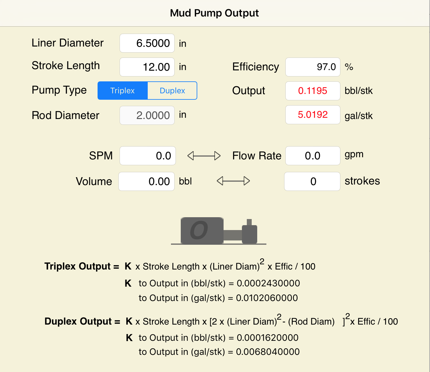
Oil and Gas drilling process - Pupm output for Triplex and Duplex pumpsTriplex Pump Formula 1 PO, bbl/stk = 0.000243 x ( in) E.xample: Determine the pump output, bbl/stk, at 100% efficiency for a 7" by 12". triplex pump: PO @ 100%,= 0.000243 x 7 x12 PO @ 100% = 0.142884bbl/stk Adjust the pump output for 95% efficiency: Decimal equivalent = 95 + 100 = 0.95 PO @ 95% = 0.142884bbl/stk x 0.95 PO @ 95% = 0.13574bbl/stk Formula 2 PO, gpm = [3(D x 0.7854)S]0.00411 x SPM where D = liner diameter, in. S = stroke length, in. SPM = strokes per minute Determine the pump output, gpm, for a 7" by 12". triplex pump at 80 strokes per minute: PO, gpm = [3(7 x 0.7854) 1210.00411 x 80 PO, gpm = 1385.4456 x 0.00411 x 80 PO = 455.5 gpm
Example:Duplex Pump Formula 1 0.000324 x (liner diameter, in) x ( stroke lengh, in) = ________ bbl/stk -0.000162 x (rod diameter, in) x ( stroke lengh, in) = ________ bbl/stk Pump out put @ 100% eff = ________bbl/stk Example: Determine the output, bbl/stk, of a 5 1/2" by 14" duplex pump at 100% efficiency. Rod diameter = 2.0": 0.000324 x 5.5 x 14 = 0.137214bbl/stk -0.000162 x 2.0 x 14 = 0.009072bbl/stk Pump output @ 100% eff. = 0.128142bbl/stk Adjust pump output for 85% efficiency: Decimal equivalent = 85 100 = 0.85 PO@85%)= 0.128142bbl/stk x 0.85 PO@ 85% = 0.10892bbl/stk Formula 2
PO. bbl/stk = 0.000162 x S[2(D) - d] where S = stroke length, in. D = liner diameter, in. d = rod diameter, in. Example: Determine the output, bbl/stk, of a 5 1/2". by 14". duplex pump @ 100% efficiency. Rod diameter = 2.0in.: PO@100%=0.000162 x 14 x [ 2 (5.5) - 2 ] PO @ 100%)= 0.000162 x 14 x 56.5 PO@ 100%)= 0.128142bbl/stk Adjust pump output for 85% efficiency: PO@85%,= 0.128142bb/stkx 0.85 PO@8.5%= 0.10892bbl/stk Metric calculation Pump output, liter/min = pump output. liter/stk x pump speed, spm. S.I. units calculation Pump output, m/min = pump output, liter/stk x pump speed, spm. Mud Pumps Mud pumps drive the mud around the drilling system. Depending on liner size availability they can be set up to provide high pressure and low flow rate, or low pressure and high flow rate. Analysis of the application and running the Drill Bits hydraulics program will indicate which liners to recommend. Finding the specification of the mud pumps allows flow rate to be calculated from pump stroke rate, SPM. Information requiredo Pump manufacturer o Number of pumps o Liner size and gallons per revolution Weight As a drill bit cutting structure wears more weight will be required to achieve the same RoP in a homogenous formation. PDC wear flats, worn inserts and worn milled tooth teeth will make the bit drill less efficiently. Increase weight in increments of 2,000lbs approx. In general, weight should be applied before excessive rotary speed so that the cutting structure maintains a significant depth of cut to stabilise the bit and prevent whirl. If downhole weight measurements are available they can be used in combination with surface measurements to gain a more accurate representation of what is happening in the well bore.

Pumps tend to be one of the biggest energy consumers in industrial operations. Pump motors, specifically, require a lot of energy. For instance, a 2500 HP triplex pump used for frac jobs can consume almost 2000 kW of power, meaning a full day of fracking can cost several thousand dollars in energy costs alone!
So, naturally, operators should want to maximize energy efficiency to get the most for their money. Even a 1% improvement in efficiency can decrease annual pumping costs by tens of thousands of dollars. The payoff is worth the effort. And if you want to remotely control your pumps, you want to keep efficiency in mind.
In this post, we’ll point you in the right direction and discuss all things related to pump efficiency. We’ll conclude with several tips for how you can maintain pumping efficiency and keep your energy costs down as much as possible.
In simple terms, pump efficiency refers to the ratio of power out to power in. It’s the mechanical power input at the pump shaft, measured in horsepower (HP), compared to the hydraulic power of the liquid output, also measured in HP. For instance, if a pump requires 1000 HP to operate and produces 800 HP of hydraulic power, it would have an efficiency of 80%.
Remember: pumps have to be driven by something, i.e., an electric or diesel motor. True pump system efficiency needs to factor in the efficiency of both the motor AND the pump.
Consequently, we need to think about how electrical power (when using electric motors) or heat power (when using combustion engines) converts into liquid power to really understand pump efficiency.
Good pump efficiency depends, of course, on pump type and size. High-quality pumps that are well-maintained can achieve efficiencies of 90% or higher, while smaller pumps tend to be less efficient. In general, if you take good care of your pumps, you should be able to achieve 70-90% pump efficiency.
Now that we have a better understanding of the pump efficiency metric, let’s talk about how to calculate it. The mechanical power of the pump, or the input power, is a property of the pump itself and will be documented during the pump setup. The output power, or hydraulic power, is calculated as the liquid flow rate multiplied by the "total head" of the system.
IMPORTANT: to calculate true head, you also need to factor in the work the pump does to move fluid from the source. For example, if the source water is below the pump, you need to account for the extra work the pump puts in to draw source water upwards.
*Note - this calculation assumes the pump inlet is not pressurized and that friction losses are minimal. If the pump experiences a non-zero suction pressure, or if there is significant friction caused by the distance or material of the pipe, these should be factored in as well.
Every foot of water creates an additional 0.434 PSI of pressure, so we"ll find the elevation head by converting the change in elevation in feet to the suction pressure created by the water.
You"ll notice that the elevation head is minimal compared to the discharge pressure, and has minimal effect on the efficiency of the pump. As the elevation change increases or the discharge pressure decreases, however, elevation change will have a greater impact on total head.
Obviously, that’s a fair amount of math to get at the pump efficiency, considering all of the units conversions that need to be done. To avoid doing these calculations manually, feel free to use our simple pump efficiency calculator.
Our calculations use static variables (pump-rated horsepower and water source elevation) and dynamic variables (discharge flow and pressure). To determine pump efficiency, we need to measure the static variables only once, unless they change.
If you want to measure the true efficiency of your pump, taking energy consumption into account, you could add an electrical meter. Your meter should consist of a current transducer and voltage monitor (if using DC) for electrical motors or a fuel gauge for combustion. This would give you a true understanding of how pump efficiency affects energy consumption, and ultimately your bank account.
Up until this point, we’ve covered the ins and outs of how to determine pump efficiency. We’re now ready for the exciting stuff - how to improve pump efficiency!
One of the easiest ways to improve pump efficiency is to actually monitor pumps for signs of efficiency loss! If you monitor flow rate and discharge (output power) along with motor current or fuel consumption, you’ll notice efficiency losses as soon as they occur. Simply having pump efficiency information on hand empowers you to take action.
Another way to increase efficiency is to keep pumps well-maintained. Efficiency losses mostly come from mechanical defects in pumps, e.g., friction, leakages, and component failures. You can mitigate these issues through regular maintenance that keeps parts in working order and reveals impending failures. Of course, if you are continuously monitoring your pumps for efficiency drops, you’ll know exactly when maintenance is due.
You can also improve pump efficiency by keeping pumps lubricated at all times. Lubrication is the enemy of friction, which is the enemy of efficiency (“the enemy of my enemy is my friend…”).
A fourth way to enhance pump efficiency is to ensure your pumps and piping are sized properly for your infrastructure. Although we’re bringing this up last, it’s really the first step in any pumping operation. If your pumps and piping don’t match, no amount of lubricant or maintenance will help.
Pipes have physical limits to how much fluid they can move at a particular pressure. If pipes aren’t sized properly, you’ll lose efficiency because your motor will have to work harder. It’s like air conditioning - if your ductwork isn’t sized appropriately for your home, you’ll end up paying more on your energy bill.
In this post, we’ve given you the full rundown when it comes to calculating and improving pump efficiency. You can now calculate, measure, and improve pump efficiency, potentially saving your business thousands of dollars annually on energy costs.
For those just getting started with pump optimization, we offer purpose-built, prepackaged solutions that will have you monitoring pump efficiency in minutes, even in hazardous environments.

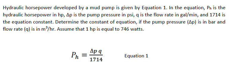
A measure of the energy per unit of time that is being expended across the bit nozzles. It is commonly calculated with the equation HHP=P*Q/1714, where P stands for pressure in pounds per square in., Q stands for flow rate in gallons per minute, and 1714 is a conversion factor necessary to yield HHP in terms of horsepower. Bit manufacturers often recommend that fluid hydraulics energy across the bit nozzles be in a particular HHP range, for example 2.0 to 7.0 HHP, to ensure adequate bit tooth and bottom-of-hole cleaning (the minimum HHP) and to avoid premature erosion of the bit itself (the maximum HHP).

A measure of the energy per unit of time that is being expended across the bit nozzles. It is commonly calculated with the equation HHP=P*Q/1714, where P stands for pressure in pounds per square in., Q stands for flow rate in gallons per minute, and 1714 is a conversion factor necessary to yield HHP in terms of horsepower. Bit manufacturers often recommend that fluid hydraulics energy across the bit nozzles be in a particular HHP range, for example 2.0 to 7.0 HHP, to ensure adequate bit tooth and bottom-of-hole cleaning (the minimum HHP) and to avoid premature erosion of the bit itself (the maximum HHP).

The purpose of this article is to present some guidelines and simplified techniques to size pumps and piping typically used in mud systems. If unusual circumstances exist such as unusually long or complicated pipe runs or if very heavy or viscous drilling muds are used, a qualified engineer should analyze the system in detail and calculate an exact solution.
To write about pumps, one must use words that are known and well understood. For example, the label on the lefthand side of any centrifugal pump curve is Total Head Feet. What does this mean?
Total Head remains constant for a particular pump operated at a constant speed regardless of the fluid being pumped. However, a pump’s pressure will increase as the fluid density (mud weight) increases according to the following relationship:
Note that the pump pressure almost doubled. It follows that the required pump horsepower has increased by the same percentage. If the pump required 50 HP for water service, it will require the following horsepower for 16 lb/gal mud:
To summarize, a pump’s Total Head remains constant for any fluid pumped, only the pump pressure and pump horsepower will change. Therefore, a pump motor must be sized according to the heaviest weight mud to be pumped.
In our example problem, the required desilter pressure head is 75 ft. for any mud weight. However, the pressure would be 30.3 PSIG for water or 43.6 PSIG for 12 lb mud or 58.1 PSIG for 16 lb mud. A good rule of thumb is that the required pressure (PSIG) equals 4 times the mud weight (12 LB/GAL x 4 = 48 PSIG).
Determine the required pressure head and flow rate. If the pump is to supply a device such as a mud mixing hopper or a desilter, consult the manufacturer’s information or sales representative to determine the optimum flow rate and pressure head required at the device. (On devices like desilters the pressure head losses downstream of the device are considered negligible and are usually disregarded.)
Select the basic pump to pump the desired flow rate. Its best to refer to a manufacturer’s pump curve for your particular pump. (See example – Figure 3).
The pump’s impeller may be machined to a smaller diameter to reduce its pressure for a given application. Refer to the manufacturer’s pump curves or manufacturer’s representative to determine the proper impeller diameter. Excessive pressure and flow should be avoided for the following reasons:
The pump must produce more than 75 FT-HD at the pump if 75 FT-HD is to be available at the desilter inlet and the pump’s capacity must be at least 800 GPM. Therefore, we should consider using one of the following pumps from the above list: 4″ x 5″ Pump 1750 RPM – 1000 GPM at 160 FT-HD; or 5″ x 6″ Pump 1750 RPM – 1200 GPM at 160 FT-HD.
The pump suction and discharge piping is generally the same diameter as the pump flange diameters. The resulting fluid velocities will then be within the recommended ranges of 4 to 10 FT/SEC for suction lines and 4 to 12 FT/
SEC for discharge lines. Circumstances may dictate that other pipe diameters be used, but remember to try to stay within the above velocity guidelines. Smaller pump discharge piping will create larger pressure drops in the piping
and the pump may not be able to pump the required amount of fluid. (For example, don’t use a 4″ discharge pipe on a 6″ x 8″ pump and expect the pump’s full fluid flow.)
6″ pipe may be used for the suction pipe since it is relatively short and straight and the pump suction is always flooded. 6″ pipe is fully acceptable for the discharge pipe and is a good choice since the desired header is probably 6″ pipe.
8″ pipe may be used for the suction pipe (V = 5.13 FT/SEC) since V is still greater than 4 FT/SEC. 8″ pipe would be preferred if the suction is long or the suction pit fluid level is low with respect to the pump.

Drilling can be looked at as system drilling fluids being just one part along with geology, equipment, and fluid flow and fluid pressure. Choosing the proper drilling fluid formulation is as easy as remembering how to use the five-finger method—treat the makeup water, create suspension, protect the borehole, protect the cuttings, and address any local issues.
One of the most widespread local issues is loss of circulation. Loss of circulation is losing whole mud to the formation, which we see as getting less volume of fluid back to the surface as compared to what was pumped down.
Second, a pressure differential must exist between the pressure exerted by the fluid in the borehole and the pressure in the formation. We intuitively know the pressure exerted by the fluid in the borehole is higher than the formation pressure if we are losing drilling fluid.
An example is when drilling through a gravel formation above the water table where the void spaces are filled with air, the hydrostatic pressure of the drilling fluid is greater than the air pressure in the formation, and fluid moves into the formation. The opposite is true if we have an artesian or flowing well; the pressure within the formation is higher than the pressure exerted by the drilling fluid, and fluid flows out of the borehole.
We seldom know exactly what the pressure from the formation is in the water well drilling business. We can calculate the hydrostatic pressure of our drilling fluid by this formula:
Hydrostatic pressure in pounds per square inch (PSI) equals mud weight (MW) in pounds per gallon times the depth (D) in feet where you want to know the pressure times a conversion factor (0.052) to connect all the units of measurement.
If this drilling fluid was present in our dry gravel example above, the only thing we know for sure is the hydrostatic pressure of 52 PSI is far greater than the formation pressure. The loss of returns in the dry gravel would be almost instantaneous. As the pressure exerted by formation fluids increases, the rate of drilling fluid losses decreases.
I have only talked so far about hydrostatic pressure, which means the drilling fluid is sitting still in the borehole and not being pumped. For the drilling fluid to circulate, additional pressure needs to be added by means of a mud pump.
As mentioned in a previous column, the pressure added is used up moving the drilling fluid from the pump to the drill pipe, down the drill pipe to the drill bit, through the bit, and up the annular space to the surface.
In the annular space, the remaining pump pressure must be added to the hydrostatic pressure to get a true fluid pressure against the formation. Most of these calculations are beyond the scope of this column, but suffice it to say a circulating fluid’s pressure against a formation is greater than the hydrostatic pressure at any given point. You may have experienced this phenomenon if you have had a borehole stand full when not circulating but start losing fluid while circulating.
One takeaway from the mathematics involved is the circulating pressure can be used to calculate an equivalent mud weight if the fluid was static. This is the drilling fluid’s equivalent circulating density.
Drilling fluid properties and drilling practices can contribute to loss of circulation. The pressure formulas use mud weight in the calculations. Water weighs 8.34 pounds per gallon (ppg), so this would be the minimum mud weight used to calculate pressures. As we add solids to water—either as beneficial drilling fluid additives to create our desired drilling fluid properties or non-beneficial solids such as drill cuttings— the mud weight increases.
As mud weight increases above 8.34 ppg, the hydrostatic pressure increases and the equivalent circulating density increases. High viscosity or thicker drilling fluids require more pump pressure to initiate circulation and maintain flow and therefore increase equivalent circulating density as well. This also holds true for drilling fluids with high gel strengths.
This would be a good time to introduce fracture gradient. Fracture gradient is the pressure gradient at which the formation breaks. If the pressure applied by the drilling fluid is higher than the formation’s fracture gradient, the formation will break and create a potential loss of returns.
How we break circulation and pull and run pipe can lead to fluid losses. If we put the mud pump immediately full on when we are ready to circulate, we send a pressure surge through the circulating system. This can have either of two effects: We could possibly exceed the formation’s fracture gradient and fracture the formation, or the pressure could be higher than the formation fluid pressure, resulting in loss of returns.
To minimize pressure surges, bring the pump on slowly until it is at your desired flow rate. Running drill pipe into the hole can have the same effect. Since the drill bit is only slightly smaller than the hole diameter, it acts as a piston in a cylinder, pressurizing the fluid in front of it. If the surge pressure is higher than the formation fracture gradient or the formation fluid pressure, we could induce loss of returns. To control this, do not let the drill pipe free-fall into the hole but run in at a rate that allows the drilling fluid to flow around the bit, minimizing the pressure surge.
There are two directions we can go. Since loss of returns is directly pressure-related, we could find a way to lower the fluid pressure exerted against the formation by the drilling fluid. This might mean changing from conventional circulation to reverse circulation, and may not be practical.
A big misconception is the plugging material needs to make a rigid plug, setting up like concrete. The plug only needs to be strong enough to redirect the direction of fluid flow. In other words, it would take more pressure to push the drilling fluid through the plug and into the formation than to flow up the annulus.
Any loss between these extremes will require varying concentrations of materials and material sizes and shapes. It is best to consult your drilling fluids supplier or local mud engineer for advice on products and concentrations.
Here are some final thoughts on lost circulation. Prevent it if possible by maintaining a good drilling fluid with low mud weight. Do not let your drilled solids concentration build up in the fluid system by utilizing effective solids control.
Follow good drilling practices and pay attention to surge pressures created by the mud pump or when running pipe. Use adequate LCM concentrations during early stages of treating the loss; the problem usually gets worse with time. When possible, combine different sizes and shapes of materials to achieve a matting effect to form a plug.

A mud motor is no more effective than the volume of fluid that is pumped through it, which generates power. If the mudflow is on the low side of specifications, the mud motor will have low bit speed and a slower penetration rate. As the pumping rate increases toward the maximum of the flow specification the motor is more powerful and efficient. This is why it is essential to match your mud motor size with the available deliverable mudflow from the pump.
Most mud pumps used in the directional boring industry run at higher speeds to operate mud motors. The draw back is that the mud pumps lose operating efficiency, particularly as mud viscosity increases and the effect of entrained air in the mud magnifies. The pumps experience incomplete filling on the suction phase of the stroke, causing a drop in the volume of fluid actually being pumped.
A properly designed, pressure-fed piston or plunger pump generally has a 96 to 97 percent volumetric efficiency. The loss is due to valves not opening and closing instantly. This efficiency goes down as mud viscosity increases and drops like a rock, if air is in the mud. Air is a hidden monster that can drop the pump efficiency to 50 percent or less. The biggest cause of entrained air in the mud is the cleaning system and its design. By the very nature of cleaning mud, agitation occurs which mixes air into the mud. Higher viscosity mud makes air entrapment worse. The design of the cleaning system must give time for the mud to expel this air before it enters the suction manifold of the pressure pump and cause cavitation damage and loss of pump efficiency. A cleaning system that eliminates sand from the mud will also reduce repair costs to mud motors and pumps.
Small internal diameters of the piping and hoses cause pressure losses as pumping rates increase. This robs available pressure away from the motor, causing a decrease in motor torque and slower boring. The smaller I.D. of the drill pipe of some rigs also tends to require a higher surface mud system pressure to off set piping losses.
Small swivel flow passages are another spot that will cause high-pressure losses and reduce efficiency of the system. A tool that eliminates the restriction of the swivel is a high-pressure, side-inlet swivel that allows the pressure hose to be hooked directly to the drill string, thereby bypassing the rig swivel and gearbox spindle.
When talking about mud pump capabilities, you have to keep in mind that when flow rates are represented by manufactures, it is usually a calculated volume based on pumping water at 100 percent efficiency. Air in the mud, the size of the restricted passages, mud viscosity and the length of the various restrictions reduce the true working efficiency of the pumps.
It almost goes without saying, but any leaks on the pressured side of the pump, including a leaking piston or plunger packing, reduce efficiency. Sonde housings that have broken windows and allow mudflow to divert out of them reduce efficiency. Leaks in the suction hoses can allow air to enter the system or allow cleaned mud to be lost. What can be done to help eliminate some of the inherent problems so that more mud can get to the motor and bit and do the best job for the work at hand?
Use larger pumps than are needed so that the mud pump does not have to be operated at 100 percent. Seventy-five percent of rated speed is a good maximum operating rpm.

On deepwater drilling, the subsea bop stack is installed at the well head (on sea bed). In kick condition, the BOP is closed and the flux is deviated to the choke at surface through the choke line. This line has a diameter normally of 3 inches and the frictional pressure losses will increase the pressure at shoe depth. This is a big problem on deepwater wells due to the formation pressure be fragile.
A method to compensate the choke line friction is to decrease the initial choke pressure of this value, monitoring the annulus pressure at the kill pressure gauge instead the choke pressure gauge when bringing the mud pump to slow circulation rate, like on a surface bop well control, and adjusting the choke to set the drill pipe pressure equal to the Initial Circulating Pressure (ICP) calculated by the formula ICP = SIDPP (Shut-in Drill Pipe Pressure) + Pump Pressure @ slow circulating rate when circulating through the drill string with return to the riser.
An option to start the circulation is monitoring the Annulus Pressure on the Choke Gauge on bringing the mud pump until the Slow Circulating Rate on reducing of the Choke Pressure the value of the Choke Line friction losses to steps of 5 spm at Pump Speed.Circulate by KILL returning to Riser to record the ΔP,cl = KILL Pressure for steps of 5 spm on Pump Speed until the SCR.


 8613371530291