
mud pump pressure formula free sample

Rig pump output, normally in volume per stroke, of mud pumps on the rig is one of important figures that we really need to know because we will use pump out put figures to calculate many parameters such as bottom up strokes, wash out depth, tracking drilling fluid, etc. In this post, you will learn how to calculate pump out put for triplex pump and duplex pump in bothOilfield and Metric Unit.

Pumps tend to be one of the biggest energy consumers in industrial operations. Pump motors, specifically, require a lot of energy. For instance, a 2500 HP triplex pump used for frac jobs can consume almost 2000 kW of power, meaning a full day of fracking can cost several thousand dollars in energy costs alone!
So, naturally, operators should want to maximize energy efficiency to get the most for their money. Even a 1% improvement in efficiency can decrease annual pumping costs by tens of thousands of dollars. The payoff is worth the effort. And if you want to remotely control your pumps, you want to keep efficiency in mind.
In this post, we’ll point you in the right direction and discuss all things related to pump efficiency. We’ll conclude with several tips for how you can maintain pumping efficiency and keep your energy costs down as much as possible.
In simple terms, pump efficiency refers to the ratio of power out to power in. It’s the mechanical power input at the pump shaft, measured in horsepower (HP), compared to the hydraulic power of the liquid output, also measured in HP. For instance, if a pump requires 1000 HP to operate and produces 800 HP of hydraulic power, it would have an efficiency of 80%.
Remember: pumps have to be driven by something, i.e., an electric or diesel motor. True pump system efficiency needs to factor in the efficiency of both the motor AND the pump.
Consequently, we need to think about how electrical power (when using electric motors) or heat power (when using combustion engines) converts into liquid power to really understand pump efficiency.
Good pump efficiency depends, of course, on pump type and size. High-quality pumps that are well-maintained can achieve efficiencies of 90% or higher, while smaller pumps tend to be less efficient. In general, if you take good care of your pumps, you should be able to achieve 70-90% pump efficiency.
Now that we have a better understanding of the pump efficiency metric, let’s talk about how to calculate it. The mechanical power of the pump, or the input power, is a property of the pump itself and will be documented during the pump setup. The output power, or hydraulic power, is calculated as the liquid flow rate multiplied by the "total head" of the system.
IMPORTANT: to calculate true head, you also need to factor in the work the pump does to move fluid from the source. For example, if the source water is below the pump, you need to account for the extra work the pump puts in to draw source water upwards.
*Note - this calculation assumes the pump inlet is not pressurized and that friction losses are minimal. If the pump experiences a non-zero suction pressure, or if there is significant friction caused by the distance or material of the pipe, these should be factored in as well.
Every foot of water creates an additional 0.434 PSI of pressure, so we"ll find the elevation head by converting the change in elevation in feet to the suction pressure created by the water.
You"ll notice that the elevation head is minimal compared to the discharge pressure, and has minimal effect on the efficiency of the pump. As the elevation change increases or the discharge pressure decreases, however, elevation change will have a greater impact on total head.
Obviously, that’s a fair amount of math to get at the pump efficiency, considering all of the units conversions that need to be done. To avoid doing these calculations manually, feel free to use our simple pump efficiency calculator.
Our calculations use static variables (pump-rated horsepower and water source elevation) and dynamic variables (discharge flow and pressure). To determine pump efficiency, we need to measure the static variables only once, unless they change.
If you want to measure the true efficiency of your pump, taking energy consumption into account, you could add an electrical meter. Your meter should consist of a current transducer and voltage monitor (if using DC) for electrical motors or a fuel gauge for combustion. This would give you a true understanding of how pump efficiency affects energy consumption, and ultimately your bank account.
Up until this point, we’ve covered the ins and outs of how to determine pump efficiency. We’re now ready for the exciting stuff - how to improve pump efficiency!
One of the easiest ways to improve pump efficiency is to actually monitor pumps for signs of efficiency loss! If you monitor flow rate and discharge (output power) along with motor current or fuel consumption, you’ll notice efficiency losses as soon as they occur. Simply having pump efficiency information on hand empowers you to take action.
Another way to increase efficiency is to keep pumps well-maintained. Efficiency losses mostly come from mechanical defects in pumps, e.g., friction, leakages, and component failures. You can mitigate these issues through regular maintenance that keeps parts in working order and reveals impending failures. Of course, if you are continuously monitoring your pumps for efficiency drops, you’ll know exactly when maintenance is due.
You can also improve pump efficiency by keeping pumps lubricated at all times. Lubrication is the enemy of friction, which is the enemy of efficiency (“the enemy of my enemy is my friend…”).
A fourth way to enhance pump efficiency is to ensure your pumps and piping are sized properly for your infrastructure. Although we’re bringing this up last, it’s really the first step in any pumping operation. If your pumps and piping don’t match, no amount of lubricant or maintenance will help.
Pipes have physical limits to how much fluid they can move at a particular pressure. If pipes aren’t sized properly, you’ll lose efficiency because your motor will have to work harder. It’s like air conditioning - if your ductwork isn’t sized appropriately for your home, you’ll end up paying more on your energy bill.
In this post, we’ve given you the full rundown when it comes to calculating and improving pump efficiency. You can now calculate, measure, and improve pump efficiency, potentially saving your business thousands of dollars annually on energy costs.
For those just getting started with pump optimization, we offer purpose-built, prepackaged solutions that will have you monitoring pump efficiency in minutes, even in hazardous environments.
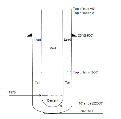
A few years ago, I received a call from a contractor asking for help mitigating a situation with a governmental transport agency in regards to monitoring downhole pressures as they were drilling under a six-lane highway crossing. They were asked to provide details on the drilling fluid they were using and the expected annular pressure while drilling. In order to do this, one must look at the functions of the drilling fluids, the properties of the drilling fluids (like viscosity and solids content), the volume of fluids being pumped, and the rate or speed of drilling.
You may be wondering what this has to do with fluid volumes and downhole pressure? The answer is quite a bit, based on the properties of the fluid being used. The contractor needs to look at the primary properties of the fluid, which are:
The higher the viscosity of the fluid, the higher the pump pressure required and the higher the downhole pressure. As the fluid is designed to suspend and transport cuttings, the amount of fresh fluid being pumped will directly affect the solids content of the fluids being displaced out of the hole. Lastly, the pressure of the drilling fluid, encapsulated by the filter cake against the formation, helps hold the hole open. The filter cake controls the fluid loss with positive pressure; however, it must be controlled in order to not exceed downhole pressure.
Therefore, looking at this example, we know that we need to move 1.02 gallons of soil per linear foot of bore. In order to do this, enough drilling fluids need to be pumped downhole in order to produce a flowable slurry. As mentioned earlier, the viscosity and solids content must be controlled in order to keep the downhole pressure manageable. In fact, a ratio of 2:1 to 3:1 of fluids per gallon of soil is needed in sand, and in clay the ratio may be up to 5:1. For example, if drilling in sand, a 2:1 ratio will be required as a minimum to produce a flowable slurry that will carry the cuttings out of the borehole. In this example, roughly 2-gallons of drilling fluid will need to be pumped per linear foot. As the diameter of the borehole increases, the amount of fluid required increased dramatically. For example, the calculation for a bore done by a 10-inch reamer is:
Without taking into account any pilot or pre-ream, the volume of soils we need to remove is 4.08 gal./ft. Therefore, in sand, we need to pump a minimum of 8.16 gal./ft. of drilling fluids to effectively displace the cuttings.
When pulling a pipe through the borehole, it is essential that the proper volume of slurry is pumped and also that there is sufficient annular space to allow for flow of the slurry. The volume of the fluid will keep the viscosity and solids content low and the slurry flowable. Without creating a flowable slurry, circulation will be lost and pressure in the borehole will increase rapidly, resulting in either a break-off or stuck pipe and/or inadvertent returns at the surface.
This now brings us to downhole pressures. The calculations of recommended downhole pressures are only as good as the geotechnical reports the contractor has. Often the engineering documents will recommend an annular pressure not to be exceeded. There is also software available that can produce this data. It is common that the available geotechnical soil reports were taken from the entry pit and the exit pit or nearby, but not necessarily along the entire planned bore path. Therefore, there can be unknown ground formations along the bore that the contractor may be unaware of unless he or she has drilled in the same area before.
In this equation, 0.052 is a unit conversion factor. It means that hydrostatic pressure (P), the result of the equation, is expressed in units of psi.
The contractor I mentioned at the beginning of this column wanted some assistance to maintain downhole pressure in order to not cause formation damage while drilling under the roadway. The reality is that, in order to do this, the contractor needs to fully understand and ensure the following: the drilling fluid’s functions and properties match the soil type; flow rate requirements are understood; and the speed of the drilling is known and monitored, all while keeping circulation constant.
A small- to medium-sized HDD driller has some options to understand the downhole pressure while drilling. On critical pullbacks, there is special instrumentation that can be installed between the reamer and the pullback string. This instrumentation can provide real-time annular pressure readings. The speed of the drilling and volume of fluids can be regulated to keep pressure consistent and below a pre-determined value. Another option is for the driller to continually measure the mud weight of the fluid returns at the exit pit. The weight of the returns can be an indicator of the downhole pressure. The higher the mud weight, the higher the annular pressure.
Spending the time to understand the fluids required, the volume and speed of drilling, and the resultant annular pressure can make the difference between success and failure. This knowledge results in bores completed on time and on budget. Keep on turning to the right!

This article will demystify the term “head” as it relates to pumps, so you should never have to worry again about what head is, how it relates to pressure or why it’s important.
It’s a concept that’s actually incredibly simple to define, but can be confusing when the concept is translated into examples involving real pumps. Imagine a pump where you have a pipe that extends straight up vertically from the discharge (see Figure 1).
Simply stated: a pump’s head is the maximum height that the pump can achieve pumping against gravity. Intuitively, if a pump can produce more pressure, it can pump water higher and produce a higher head. Also note that the higher the liquid in the tank, the higher the pump will be able to pump the water into the vertical discharge pipe, due to the head exerted by the liquid in the suction tank (see Figure 2).
A much more useful measure of head is the difference between the liquid level in the suction tank and the head in the vertical discharge pipe. This number is known as the “total head” that the pump can produce.
Increasing the level of the liquid in the suction tank will give rise to increased head, and decreasing the level will give rise to a lower head. Pump manufacturers and suppliers often won’t tell you how much head a pump can produce, because they can’t predict what the height of the liquid in your suction tank will be. Instead, they will report the pump’s total head, the difference in height between the level of liquid in the suction tank and the height of a column of water that the pump can achieve. Total head is independent of the level of liquid in the suction tank.
Where Htis the total head, Hd is the discharge head and Hs is the suction head. Also be aware that this equation holds true whether the suction head is positive (level of liquid in the suction tank is above the pump) or negative (level of the liquid in the suction tank is below the pump). See Figure 4 for an example of the latter situation. In this case, the pump will still produce the same total head, but because the suction head is negative, the discharge head will be reduced by this amount, according to our equation.
In Figure 5 a pump is transferring liquid from the suction tank into a vertical pipe where the liquid rises until it can’t overcome the force of gravity and it quits rising. In this situation, the flow of the pump is zero. The pump is working, but the force of gravity causes the water’s rise in the vertical discharge pipe to stop and the net flow stops. This is known as the “shut-off head”, it’s the amount of head a pump can produce at zero flow.
To choose your required pump, you need to know two things: the total head and what flow rate you require. As you might expect, these two quantities are related. The maximum head (shut-off head) is achieved at a flow rate of zero. Increasing flow rate introduces friction into the system as the liquid travels along the pipes from the suction tank to the pump and from the pump into the discharge pipe. This friction reduces the amount of total head that the pump can produce. In fact, as the flow increases, friction increases and the total head continues to decrease. The amount of head that is lost due to friction is called “friction head” or “friction-loss”(see Figure 5 and Figure 6).
In a system where there is flow, the total head is the difference between the discharge head and the suction head plus the friction head and this sum will be less than the shut-off head. The plot of head versus flow rate is known as the pump’s performance curve (see Figure 7 for an example of a pump performance curve).
Every centrifugal pump will be supplied with a performance curve plotting head versus flow rate. The required flow rate and total head will intersect at a certain point on the pump’s performance curve and comparing this to the pump’s curve will allow you to determine whether that particular pump will be appropriate (i.e. will it produce enough head at the required flow rate?) for your needs.
Why is head used as a measure of a pump’s ability to pump liquids rather than pressure? Historically, many pumps were used to pump water uphill to a higher level – for example into a storage tank at the top of a hill. If you have to pump water to a height of 60 metres to get it up the hill, then using head – measured in metres – is natural. You automatically know that if a pump doesn’t have 60 metres of head, it’s not appropriate for your application.
Another reason that head is used, is that as long as the liquid that is being pumped has a similar viscosity to water, the head will be identical for different liquids. This may or may not be the case when using pressure to define a pump’s characteristics. Although some pump manufacturers do use pressure to characterise their pumps, the vast majority of pumps are still characterised by the total head they produce.
We hope you found this blog post helpful. Head to our blog page to learn more about how toreduce friction in suction/discharge linesorhow to check flow and head pressure.
Global Pumps are a leading Australian industrial pump supplier for mining, government, wine, food, beverage, chemical processing, paint, print, packaging and manufacturing industries.
We provide experttechnical advice,mechanical and chemical engineering services, and maintenance services for pumps, pumping systems and complete turn-key packages.
Our pump engineers and sales consultants are available to help you to select the right pump or system to suit your specific industry application needs, to achieve efficiencies, increased productivity and reduced downtime.

Drilling can be looked at as system drilling fluids being just one part along with geology, equipment, and fluid flow and fluid pressure. Choosing the proper drilling fluid formulation is as easy as remembering how to use the five-finger method—treat the makeup water, create suspension, protect the borehole, protect the cuttings, and address any local issues.
One of the most widespread local issues is loss of circulation. Loss of circulation is losing whole mud to the formation, which we see as getting less volume of fluid back to the surface as compared to what was pumped down.
Second, a pressure differential must exist between the pressure exerted by the fluid in the borehole and the pressure in the formation. We intuitively know the pressure exerted by the fluid in the borehole is higher than the formation pressure if we are losing drilling fluid.
An example is when drilling through a gravel formation above the water table where the void spaces are filled with air, the hydrostatic pressure of the drilling fluid is greater than the air pressure in the formation, and fluid moves into the formation. The opposite is true if we have an artesian or flowing well; the pressure within the formation is higher than the pressure exerted by the drilling fluid, and fluid flows out of the borehole.
We seldom know exactly what the pressure from the formation is in the water well drilling business. We can calculate the hydrostatic pressure of our drilling fluid by this formula:
Hydrostatic pressure in pounds per square inch (PSI) equals mud weight (MW) in pounds per gallon times the depth (D) in feet where you want to know the pressure times a conversion factor (0.052) to connect all the units of measurement.
If this drilling fluid was present in our dry gravel example above, the only thing we know for sure is the hydrostatic pressure of 52 PSI is far greater than the formation pressure. The loss of returns in the dry gravel would be almost instantaneous. As the pressure exerted by formation fluids increases, the rate of drilling fluid losses decreases.
I have only talked so far about hydrostatic pressure, which means the drilling fluid is sitting still in the borehole and not being pumped. For the drilling fluid to circulate, additional pressure needs to be added by means of a mud pump.
As mentioned in a previous column, the pressure added is used up moving the drilling fluid from the pump to the drill pipe, down the drill pipe to the drill bit, through the bit, and up the annular space to the surface.
In the annular space, the remaining pump pressure must be added to the hydrostatic pressure to get a true fluid pressure against the formation. Most of these calculations are beyond the scope of this column, but suffice it to say a circulating fluid’s pressure against a formation is greater than the hydrostatic pressure at any given point. You may have experienced this phenomenon if you have had a borehole stand full when not circulating but start losing fluid while circulating.
One takeaway from the mathematics involved is the circulating pressure can be used to calculate an equivalent mud weight if the fluid was static. This is the drilling fluid’s equivalent circulating density.
Drilling fluid properties and drilling practices can contribute to loss of circulation. The pressure formulas use mud weight in the calculations. Water weighs 8.34 pounds per gallon (ppg), so this would be the minimum mud weight used to calculate pressures. As we add solids to water—either as beneficial drilling fluid additives to create our desired drilling fluid properties or non-beneficial solids such as drill cuttings— the mud weight increases.
As mud weight increases above 8.34 ppg, the hydrostatic pressure increases and the equivalent circulating density increases. High viscosity or thicker drilling fluids require more pump pressure to initiate circulation and maintain flow and therefore increase equivalent circulating density as well. This also holds true for drilling fluids with high gel strengths.
This would be a good time to introduce fracture gradient. Fracture gradient is the pressure gradient at which the formation breaks. If the pressure applied by the drilling fluid is higher than the formation’s fracture gradient, the formation will break and create a potential loss of returns.
How we break circulation and pull and run pipe can lead to fluid losses. If we put the mud pump immediately full on when we are ready to circulate, we send a pressure surge through the circulating system. This can have either of two effects: We could possibly exceed the formation’s fracture gradient and fracture the formation, or the pressure could be higher than the formation fluid pressure, resulting in loss of returns.
To minimize pressure surges, bring the pump on slowly until it is at your desired flow rate. Running drill pipe into the hole can have the same effect. Since the drill bit is only slightly smaller than the hole diameter, it acts as a piston in a cylinder, pressurizing the fluid in front of it. If the surge pressure is higher than the formation fracture gradient or the formation fluid pressure, we could induce loss of returns. To control this, do not let the drill pipe free-fall into the hole but run in at a rate that allows the drilling fluid to flow around the bit, minimizing the pressure surge.
There are two directions we can go. Since loss of returns is directly pressure-related, we could find a way to lower the fluid pressure exerted against the formation by the drilling fluid. This might mean changing from conventional circulation to reverse circulation, and may not be practical.
A big misconception is the plugging material needs to make a rigid plug, setting up like concrete. The plug only needs to be strong enough to redirect the direction of fluid flow. In other words, it would take more pressure to push the drilling fluid through the plug and into the formation than to flow up the annulus.
Any loss between these extremes will require varying concentrations of materials and material sizes and shapes. It is best to consult your drilling fluids supplier or local mud engineer for advice on products and concentrations.
Here are some final thoughts on lost circulation. Prevent it if possible by maintaining a good drilling fluid with low mud weight. Do not let your drilled solids concentration build up in the fluid system by utilizing effective solids control.
Follow good drilling practices and pay attention to surge pressures created by the mud pump or when running pipe. Use adequate LCM concentrations during early stages of treating the loss; the problem usually gets worse with time. When possible, combine different sizes and shapes of materials to achieve a matting effect to form a plug.


 8613371530291