
mud pump pressure problems factory

Mud pump is the key equipment in drilling operation. If mud is compared to blood in drilling operation, mud pump is the heart of blood supply in drilling production. Therefore, its importance in drilling production is self-evident, and the spare parts of mud pump play a certain role in this.
Mud pump is a kind of machine which can transport mud or water to drill hole in the process of drilling. It is an important part of drilling equipment. Its main function is to inject mud into the well with the bit, cool the bit, clean the drilling tool, stabilize the well wall, drive the drilling, and bring the cuttings back to the ground after drilling.
In the normal circulation drilling, the mud pump is to send the surface flushing medium - clear water, mud or polymer flushing liquid under a certain pressure through the high-pressure hose, faucet and the center hole of drill string directly to the bottom of the drill bit, so as to cool the drill bit, remove the cuttings and transport them to the surface. The mud pump is driven by the power machine to rotate the crankshaft of the pump. The crankshaft drives the piston to do reciprocating motion in the pump cylinder through the crosshead. Under the alternating action of the suction and discharge valves, the purpose of pressing and circulating the flushing fluid is realized. Different types of mud pumps are used in different cases to ensure the smooth proceeding of the drilling operation.
According to the use of the mud pump, the leakage of the valve box, the burning of the bearing and the abnormal noise are all frequent faults that affect the normal use of the mud pump. Therefore, careful study of the causes of the problem plays a key role in prolonging the service life of the mud pump. At this time, a certain amount of spare parts of the mud pump are needed.
In the process of using the mud pump, the equipment failures caused by specific reasons are different. Reasonable use and maintenance of the equipment can extend the service life of the equipment. At the same time, in strict accordance with the basic elements of normal operation of the drilling pump, "medium power, medium pump pressure, medium speed operation, tight, tight, leak tight, pump pressure does not fluctuate, temperature is normal, sound is normal", the operation can ensure the good operation of the equipment. Of course, it"s also important to find the right mud pump spare parts!

According to the use of mud pumps in the jurisdiction, valve box puncture, bearing burnout, and abnormal noise are all frequent failures that affect the normal use of mud pumps. Therefore, carefully studying the causes of the above problems plays a key role in prolonging the service life of the mud pump.
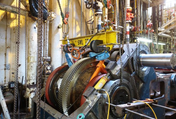
The drilling mud pump valve box is an important component of the hydraulic end of the mud pump, because the working conditions of the mud pump valve box are harsh working environments such as high pressure, high sprint, and high abrasiveness.
The main reasons for the leakage of the valve box of the mud pump are: long-term high-pressure use, the material of the valve box is fatigued, and when penetrating cracks occur, the current conditions cannot be repaired.
Because the working conditions of the drilling pump valve are very bad, the valve disc and valve seat of the discharge and suction valves have an impact in each flush. The higher the pump speed, the greater the impact and scour wear.
Because of this, the working frequency of the drilling pump is not very high. Even so, the working life of the mud pump valve is still very short, and it is one of the weakest links in the drilling pump. The valve disc and valve seat need to be replaced frequently during work.
At the same time, check the inner and outer walls of the valve box. When installing and replacing the valve disc and valve seat, the valve seat must be cleaned to ensure that the fitting surface of the mud pump valve box and the valve seat is clean and free of contamination, and there can be no anti-rust oil on the valve seat, and do not apply any oil stains.
Through correct installation and replacement of valve disc, valve seat and careful inspection of valve box, the fatigue limit of valve box can be reduced, thereby prolonging the service life of mud pump valve box.
However, penetrating cracks cannot be seen with the naked eye. Now we basically rely on experience in repairs, and it is difficult to fundamentally solve the problem. Many valve boxes are dark wounds that cannot be determined penetrating during maintenance. Its use can be determined from the integrity of the surface of the valve box of the mud pump.
Some valve boxes with good appearance will be completely punctured as long as they are exposed to high pressure during the specific use process. Therefore, many repaired valve boxes will be seriously punctured within a few days after being put into the well, causing rework and making us overhaul. The service life of the latter pump head is significantly shortened.

The fluid end of a duplex or triplex pump offers hundreds of opportunities for error. The results of an error in such a high-pressure system can mean (1) expensive downtime on the pump and maybe the entire rig, (2) expensive repair-replacement, and (3) possible injury or death of a crewman or a company man. Under the laws of nature, pump pistons and liners will wear, and there will be some corrosion and metallurgical imperfections, but the majority of pump failures are manmade. Theoretically, thorough training and retraining should avoid most mud pump problems. Realistically, a critical failure analysis during repair will be necessary to determine how to correct the failure. Telltale signs of trouble are distortion of piston rods, frayed piston polymer, discoloration, odor, hard-to-remove piston, rod cracks, pitting, total fracture, valve seat wear, and unsuitable external appearance.
Most hydraulic system failures can be classified as either a pressure problem or a volume problem. It normally is easy to tell which of these you are experiencing if you understand the difference between pressure and flow.
This critical concept was covered in my recent Machinery Lubrication article titled “Hydraulic Pressure vs. Flow: Understanding the Difference.” Armed with this knowledge, you can troubleshoot any system by simply eliminating the components that could not be causing the problem, isolating the components that could be causing the problem and then making checks of the possible culprits.
In my experience, once a pressure problem is encountered, the first component to be changed is the hydraulic pump. This frequently is a mistake. A common misconception is that pressure comes from the pump, thus making it the most likely suspect. Quite the contrary, while it is possible for the pump to be the cause of a pressure problem, it certainly isn’t the most likely cause. Usually, something else is faulty. The fastest way to determine the real cause while protecting the system from further damage is to use the following four essential steps.
You also will need to have a good understanding of the symptoms. Was the system working fine and then suddenly lost pressure, or did it happen gradually? Was it accompanied by a strange noise or an increase in temperature? If so, where in the system did the sound or heat originate?
A well-designed system typically will have some way to isolate the power supply from the rest of the machine. A manual valve is commonly used, but it may be necessary to plug a line. In the example schematic, there is a manual valve between the system relief valve and the directional valve. Close it and see what, if anything, changes. This often can cut your troubleshooting time in half. For instance, if the pressure is low and nothing moves, but when the manual valve is closed, the pressure builds and the relief valve begins to dump, you know the power supply is working fine and the problem is somewhere downstream. By the same token, if nothing changes, obviously the problem is in the power supply.
Once you have traced the flow on the schematic, identified all the components that could cause a pressure problem and isolated the power supply to determine which part of the system has the problem, start making checks. List the suspect components in order of the easiest to the most difficult to check and make the easiest checks first. I have frequently seen people make the mistake of going immediately to the worst-case scenario, spending hours and large sums of money to replace very expensive components only to find that they were not the cause of the problem.
In the previous example, let’s assume no change in pressure was observed by isolating the power supply, suggesting one of the power supply components to be at fault. In this system, there is a suction strainer, pump and relief valve. Any of these components could cause a loss of pressure. Is there a whining sound? If so, perhaps the pump is cavitating. The most common cause of cavitation is a plugged suction strainer. The suction strainer typically is inside the reservoir, below the oil level, out of sight and out of mind. It isn’t checked or cleaned as regularly as it should be.
Of course, the pump cannot deliver more oil than it can take in, which can result in reduced flow. Sometimes the flow can be drastically reduced. This often will occur gradually with the increase in sound corresponding to reduced speed, but it can also happen suddenly if a large amount of sludge is stirred up by turbulence in the reservoir. Usually, it only takes a few minutes to check by pulling the suction line and inspecting the strainer. If it is blocked, it can be cleaned with compressed air.
If there is no whining sound, check the relief valve. With the system deadheaded, try to adjust the relief valve. If it will not adjust, chances are it could be stuck open. Bleed down any residual pressure, lock out the system and pull the relief valve. Look inside for trash, bent or broken springs, excessive wear, or anything that could keep it from seating properly. Pay particular attention to orifices.
In one case, the relief valve had been pulled and checked prior to my arrival. I was told that they had found two orifices, but both were clear. I asked that they pull it again so that I could check it myself before we eliminated it as the problem. Sure enough, there was a third orifice that they had not seen, and it had a small piece of debris, perhaps the size of a grain of sand, lodged inside. We cleaned the orifice, reassembled and reinstalled the relief valve, and the pressure came back up to normal.
The final possibility in the power supply is the pump. In the example system, a fixed-displacement pump is used. The best way to check this pump is through the system relief valve. Install a flow meter in the relief valve tank line. Sometimes, this is not possible due to the machine configuration. Perhaps the relief valve is attached directly to the reservoir or mounted in a manifold that is directly attached to the reservoir. In this case, install the flow meter in the pressure line of the pump.
If the hand valve is closed, deadheading the system, you know that any flow from the pump has only the flow path through the relief valve back to the tank. Turn the relief valve adjustment counterclockwise to a very low pressure. Some relief valves do not have a stop on their adjustment, so it may back all the way out. Adjust the valve counterclockwise until no spring resistance is felt.
When the system is turned on, the pump flow should dump across the relief valve at a very low pressure. Since there is no resistance to the pump flow, it will deliver all or nearly all its flow. Gradually increase the pressure setting of the relief. If the pump can maintain flow with the relief valve set at the normal system pressure, the pump is good. If, however, the flow drops as the pressure is increased, the pump should be replaced.
Suppose pressure built in the system when the hand valve was closed to isolate the power supply. Then you know the problem is downstream. Bypassing across the directional valve or across the cylinder is causing the pressure loss. In most systems, the directional valve would be the easier component to check first. Are the solenoids firing? Notice the tandem center position. There will be no pressure in the system unless one of the solenoids is energized. Check for a magnetic field with a metal ruler or small screwdriver while each solenoid is energized.
A good way to test a directional valve for bypassing is to remove the lines from the manifold, cap off its “A” and “B” port lines and attach a hand pump with a gauge to the “P” port line. The “T” port can be run to a bucket so you can observe any oil that bypasses.
In the case of the example, notice the tandem center position. Because of the tandem center, you can only test the valve when it is in its “A” and “B” positions. Manually shift the valve to its “A” position, holding it shifted while operating the hand pump. Bring the pressure up near the normal system pressure and see if it holds. Try the same with the valve shifted to the “B” position. Pressure should hold for at least one minute with no bypassing to the tank. If pressure drops immediately, the valve is bad and must be replaced.
If the valve is good, test the cylinder. Remove any load from the cylinder. This may require disconnecting the rod from whatever it moves and may be time consuming, which is the primary reason testing the cylinder should be last. Fully extend the cylinder, then shut down the system and bleed any pressure, leaving the cylinder extended. Install a flow meter in the cylinder’s rod-side line. Power up the system and apply pressure to the full piston side of the cylinder. There should be no flow reading on the flow meter, and you should not be able to see fluid moving inside.
Use a logical progression of troubleshooting. Often, I see the “shotgun” method of simply changing parts until the problem goes away. This is wasteful not only in part costs but also downtime as well. Never remove a component unless you have good reason to believe it is bad. Whenever something is removed from the system, the lines are open to airborne contaminants. Contaminants much too small to see can do serious damage. While you may be fixing a problem today, you very well may be adding more problems later.

Insufficient NPSH AvailableSuction pressure is incorrect meaning pump is cavitating. Ensure all valves are open, check liquid temperature. To correct increase fluid in tank, check for air ingress, remove unnecessary bends, increase pipe diameter, install feed pump.
Ensure all valves are open, check liquid temperature. To correct increase fluid in tank, check for air ingress, remove unnecessary bends, increase pipe diameter, reduce fluid temperature, install feed pump.
PulsationSuction pressure is incorrect meaning pump is cavitating. Ensure all valves are open, check liquid temperature. To correct increase fluid in tank, check for air ingress, remove unnecessary bends, increase pipe diameter, reduce fluid temperature, install feed pump.
Seals or CupsScored PlungersCheck for Chemical wear, hard water, and abrasive particles. Increase service intervals as high wear to lo and high pressure seals can cause male adapter to come into contact with plunger.
Inlet pressure too HighMaximum inlet pressure for piston pumps is 40psi (2.75 bar) and plunger pumps is 60-70psi (4-4.8bar). K Style pumps can accept higher inlet pressures.
Pump Dry RunningCheck Fluid level and that NPSHR is being met. Check inlet pipework, and filters for blockage, long suction lines, and presence of air ingress
Water in CrankcaseSpraying / Air CondensationProtect pump from direct spray with ventilated enclosure if necessary. Contaminated oil will damage bearings and other components within the drive.
Worn AdaptorSplit manifold designs of pumps have adapters within the pumps. Check O rings when servicing seals and valves and replace as required.
Manifold Wear / DamageCheck chemical compatibility of fluid and any cleaning fluids used. Operation with worn seals and o rings can accelerate manifold wear. Erosion can be limited by freshwater flushing between pump use.
Manifolds can be damaged by over pressure which may be caused by high inlet pressure, relief valve or regulating valve failure or blockage within pump.

Today"s economy requires that greater attention be given to improve performance of drilling equipment. Understanding the operation of the piston (slush) pump and the associated mud system is vital to improving operations. Improved operation of the piston pump is achieved by providing a mud supply which insures proper filling of the piston pump on each stroke. Testing in a high pressure mud pump research laboratory provided the substantiation of the analytical design approach presented in this paper.Noisy or Normal Pump Operation
Unusual noise or knocks resulting from various problems. Some are mechanical; parts are loose or broken and must be repaired. One unusual knock is called valve hammer1; which is usually a result of valve and spring design and pump speed. This can also be the result of wear or broken springs. A common noise is hydraulic knock; this is a result of inadequate suction pressure at the operating speed. It results in separation of fluid and piston; this results in water hammer.2 Air intrusion may also cause sound effects where large amounts sometimes cause knocking and small amounts produce a quietening effect. Leaks causing air intrusion should be sealed throughout the piping system and air traps avoided. Air entering through pump packing or pistons on triplex pumps 3 can be eliminated by using new parts or by keeping the cylinder pressure above atmospheric pressure at all times throughout the stroke.Required Suction Pressure Fundamentals
A specific amount of pressure is necessary to force the mud from the tank through the suction piping system into the pump through the valves and against the piston in order to keep the line full of mud. If the line is not full at every point, a void will occur. These voids begin to occur at a particular pump speed. The piston speed varies throughout the stroke. If a void has developed, filling occurs in the last portion of the stroke. When the fluid catches the piston, a collision and knock occur.
The pressure needed to prevent a void is greatest at the start of the stroke. This happens because the piston velocity and the mud in the line to a cylinder is standing still; inertia is high and the mud is difficult to move or accelerate. A large amount of pressure is required to start motion at the rate at which the power end is moving the piston. Pressure is needed to overcome the piping friction and to overcome the inertia of the mud.

When choosing a size and type of mud pump for your drilling project, there are several factors to consider. These would include not only cost and size of pump that best fits your drilling rig, but also the diameter, depth and hole conditions you are drilling through. I know that this sounds like a lot to consider, but if you are set up the right way before the job starts, you will thank me later.
Recommended practice is to maintain a minimum of 100 to 150 feet per minute of uphole velocity for drill cuttings. Larger diameter wells for irrigation, agriculture or municipalities may violate this rule, because it may not be economically feasible to pump this much mud for the job. Uphole velocity is determined by the flow rate of the mud system, diameter of the borehole and the diameter of the drill pipe. There are many tools, including handbooks, rule of thumb, slide rule calculators and now apps on your handheld device, to calculate velocity. It is always good to remember the time it takes to get the cuttings off the bottom of the well. If you are drilling at 200 feet, then a 100-foot-per-minute velocity means that it would take two minutes to get the cuttings out of the hole. This is always a good reminder of what you are drilling through and how long ago it was that you drilled it. Ground conditions and rock formations are ever changing as you go deeper. Wouldn’t it be nice if they all remained the same?
Centrifugal-style mud pumps are very popular in our industry due to their size and weight, as well as flow rate capacity for an affordable price. There are many models and brands out there, and most of them are very good value. How does a centrifugal mud pump work? The rotation of the impeller accelerates the fluid into the volute or diffuser chamber. The added energy from the acceleration increases the velocity and pressure of the fluid. These pumps are known to be very inefficient. This means that it takes more energy to increase the flow and pressure of the fluid when compared to a piston-style pump. However, you have a significant advantage in flow rates from a centrifugal pump versus a piston pump. If you are drilling deeper wells with heavier cuttings, you will be forced at some point to use a piston-style mud pump. They have much higher efficiencies in transferring the input energy into flow and pressure, therefore resulting in much higher pressure capabilities.
Piston-style mud pumps utilize a piston or plunger that travels back and forth in a chamber known as a cylinder. These pumps are also called “positive displacement” pumps because they literally push the fluid forward. This fluid builds up pressure and forces a spring-loaded valve to open and allow the fluid to escape into the discharge piping of the pump and then down the borehole. Since the expansion process is much smaller (almost insignificant) compared to a centrifugal pump, there is much lower energy loss. Plunger-style pumps can develop upwards of 15,000 psi for well treatments and hydraulic fracturing. Centrifugal pumps, in comparison, usually operate below 300 psi. If you are comparing most drilling pumps, centrifugal pumps operate from 60 to 125 psi and piston pumps operate around 150 to 300 psi. There are many exceptions and special applications for drilling, but these numbers should cover 80 percent of all equipment operating out there.
The restriction of putting a piston-style mud pump onto drilling rigs has always been the physical size and weight to provide adequate flow and pressure to your drilling fluid. Because of this, the industry needed a new solution to this age-old issue.
As the senior design engineer for Ingersoll-Rand’s Deephole Drilling Business Unit, I had the distinct pleasure of working with him and incorporating his Centerline Mud Pump into our drilling rig platforms.
In the late ’90s — and perhaps even earlier — Ingersoll-Rand had tried several times to develop a hydraulic-driven mud pump that would last an acceptable life- and duty-cycle for a well drilling contractor. With all of our resources and design wisdom, we were unable to solve this problem. Not only did Miller provide a solution, thus saving the size and weight of a typical gear-driven mud pump, he also provided a new offering — a mono-cylinder mud pump. This double-acting piston pump provided as much mud flow and pressure as a standard 5 X 6 duplex pump with incredible size and weight savings.
The true innovation was providing the well driller a solution for their mud pump requirements that was the right size and weight to integrate into both existing and new drilling rigs. Regardless of drill rig manufacturer and hydraulic system design, Centerline has provided a mud pump integration on hundreds of customer’s drilling rigs. Both mono-cylinder and duplex-cylinder pumps can fit nicely on the deck, across the frame or even be configured for under-deck mounting. This would not be possible with conventional mud pump designs.
The second generation design for the Centerline Mud Pump is expected later this year, and I believe it will be a true game changer for this industry. It also will open up the application to many other industries that require a heavier-duty cycle for a piston pump application.

The problem is that the instantaneous shifting of a hydraulic cylinder from one direction to the other while under high pressure causes tremendous hydraulic hammer shock - so great that hydraulic system components could not stand up to the abuse. This shifting shock problem has been the single biggest barrier to developing a successful hydraulic drive system.
Solution: Our patented shock suppression hydraulic shifting system has tamed the hydraulic hammer shock problem. Our shifting system can shift at hydraulic oil pressures of up to 5000 psi - producing mud pressures up to 800 psi without encountering the deteriorating shock that has stumped so many other attempts at making a direct hydraulic drive.
Solution: Why overcome a problem when you can simply go around it? Our patented "Matched Displacement Ratio" technology has eliminated the need for a synchronization system. This technology allows our pumps to deliver smooth, constant discharge flow without the use of a synchronization system.
The drilling industry demands a mud pump that will operate day in and day out without continual down time maintenance. Off the shelf components that would produce such a hydraulic drive system were not to be found. A new generation of components would have to be developed to meet the demands of this service.
Solution:To make a hydraulic drive system that will stand up to the duty our industry demands, every component in our hydraulic system had to be custom engineered - developed exclusively for our pumps to stand up to a level of duty that off the shelf hydraulic components would never stand up to. Everything from the allow used in the valve castings, the design of the valve components, the hydraulic cylinder design and the type and material of the seals, were specifically engineered for use in our pumps - engineered for a 60,000,000 cycle life under high pressure reciprocating duty.
Developing new fluid end expendables that will stand up to the duty in our industry the same way that mechanical drive pump expendables hold up is a tall order. How do you improve on the one thing that has made mechanically driven mud pumps the backbone of the industry
Solution:Honestly, we couldn"t develop better fluid end expendables than those used in mechanical pumps - so we used theirs. Our fluid end expendables are the same components that have been used in mechanical pumps for decades. These expendables are proven, reliable, and available - how could we improve on that? Well, actually, by using bigger pistons and running them at half the speed of mechanical drive pumps we can get about twice the life from them!
Developing respect for a new mud pump technology doesn"t come easy. Despite their weight, size and performance limitations, the mechanical pumps that had been the standard of the industry had been getting the job done for over 50 years. How could we convince our industry to adopt our pump as the new standard for our industry?
Solution: We can claim that our pumps perform like no other pump on the market. We can claim that we use the best components and materials. But in the end, respect only comes from earning it. It doesn"t matter what we say. What matters is what our customers say. Centerline pumps are getting the job done from Canada to Australia. Are you ready for the mud pump you"ve always needed?

This service is unique from the competition because we offer unmatched timely diaphragm pump troubleshooting, installations, repairs, modifications and replacement services accompanied with exceptional customer service and after-repair-services. It’s our quality services, industry experience worth decades, an experienced team of pump experts and a pool of state-of-the-art modern equipment, machinery and parts that set us apart from our competition.
We can partner and work together long-term to ensure that your fluid flow control equipment works effectively and in case of problems, get the bad components replaced or repaired as soon as possible, or get your new plant’s diaphragm pumps working as per your specifications. We assure you of quality services to meet your needs and great outcomes to keep you happy. After all, your happiness is our happiness and so is your success.
As such, your needs and happiness comes first. Therefore, we do what’s within our powers to provide industrial pumping solutions tailored to meet your unique needs. We are here for you.
We offer full service, including troubleshooting, repair, installation, replacement and modification of your pumps. We do diaphragm pump flow rate calculation in-house, so we’re truly a one-stop-shop for all your flow control needs.

The X-series mud pump type PD X-3.004 SG HDD manufactured by PRIME DRILLING impresses with its robust and low-wear design. The 7-fold bearing mounted drive shaft, which is equipped with 3 eccentric wheels, replaces the conventional crankshaft. Due to the revolution of these shafts and their maximum 230 rotations per minute operational wear of rubbers and liners are reduced to a minimum.
The pump is driven by a 470 kW CAT engine. This type of mud pump is exclusively manufactured in our Wenden plant, i.e. „made in Germany“. Its electronic gearshift in combination with eccentric wheels used instead of a crankshaft make it a high- power but low- maintenance product. All valves and plungers also comply with API standards.


 8613371530291