
mud pump pulsation dampener function supplier
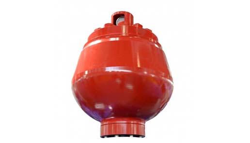
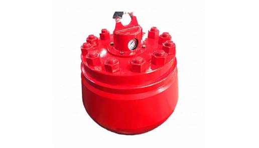
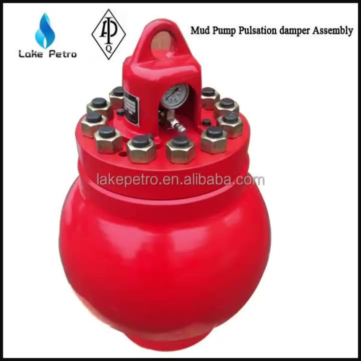
Mud Pump Pulsation Dampener is usually installed on the discharge line to reduce the fluctuation of pressure and displacement of the drilling mud pump.
Mud Pump Pulsation Dampener is a pneumatic device built into the outflow line of each UUD pump to dampen the pressure fluctuations resulting from the action of the pump. Although presented as a surge tank, this device is really a device that can be tuned to greatly diminish the output pulsations transmitted downstream from the mud pump. Unfortunately, the effectiveness of the pulsation dampener is a function of both output pump pressure and frequency of the pump pulsations.
BW Series Mud Pumps are mainly used for supplying flushing fluid to the borehole in core, geothermal, water resource, shallow oil, CBM and other drilling process. The fluid can be divided into mud, water, etc. They also can be used as transfer pumps of the above-mentioned medium. This series of mud pumps are with simple structure and easy to maintain and operate. Piston, lip-shaped and self-sealing type, is made of rubber or PTFE and nylon pads, equipped with shock-resistant pressure gauge, necessary spare parts and special tools. Bi-metal liner can be used to extend service life of pump greatly.
NBB Series Mud pumps are mainly used for the core, coal geology, metallurgy geology, hydrogeology engineering hole drilling fluid is supplied, flushing fluid can be divided into mud, water, etc., may be used as the above medium pump.
The mud pump is crank structure, horizontal triplex single acting piston pump, the piston is self-sealing lip, made of rubber or PTFE and nylon protective pads pressed, the pump adopts auto gearbox, variable five kinds of flow, the pump is compact, high efficiency, durable, safe, reliable, easy maintenance, low maintenance costs.
ZB Series grouting pumps are mainly used for kinds of weak corrosivity viscous and nonviscous liquid grouting(such as water, mud), especially for vertical shaft working face grouting, goaf filling, coal mine water inrush governance and so on.
The pump is triplex single-acting plunger high pressure pump, fitted with international first-class gearbox, which is of features like compact structure, multistage speed regulation, realizing different flow rate and pressure, meeting the grouting requirements of different formation. Electric motor drives triplex pump through transmission system. It has many advantages, like convenient adjustment for pressure and flow rate, long service life and so on.
3NB & 5NB Series Mud Pumps are mainly used for oil, water well, geothermy, CBM, shale gas, coalfield exploration, freezing well as well as well other drilling ,well cementation, work-over and other operations in industrial and mining enterprises. It is used for transferring mud, clay gum, mortar and other medium to the borehole. The pump adopts international advanced technology. It is characterized by advanced structure, reliable operation, good suction performance, long service life of wearing parts, easy for maintenance and repairing and so on.
F Series Mud Pumps are mainly used in oil field and geological prospecting for well drilling, well work-over, cementing, water shut off, water flooding and sending mud, clay, grout and so on.
A properly serviced pulsation dampener is critical for your mud pumps’ efficiency, safety, and performance. Unfortunately, there aren’t many resources available to educate personnel on executing safe and effective servicing procedures. Please review the following steps with your personnel for safe pulsation dampener maintenance.
Should you or your personnel have any questions regarding pulsation dampener maintenance, please don’t hesitate to ask. Sigma is more than happy to help you to ensure safe and proper care is being completed on your pulsation dampening equipment.
Pulsation dampeners (also called pulsation dampers) are used for stabilizing the flow and the pressure in circuits with volumetric or dosing pumps. They are used in a wide range of applications.
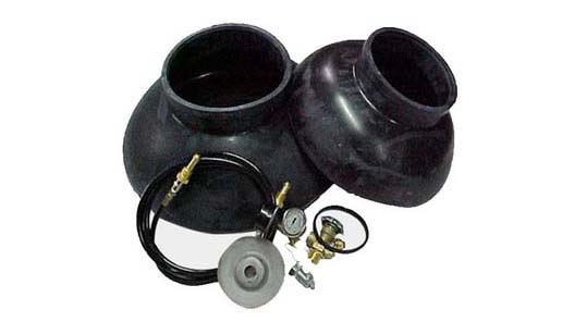
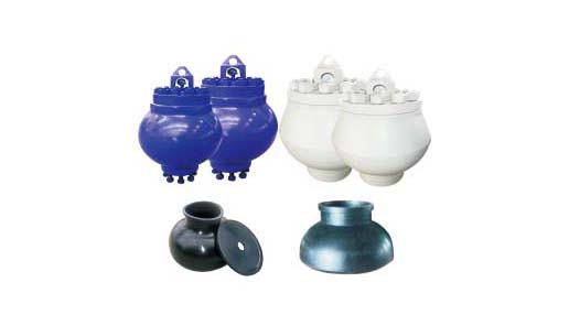
In every pulsation dampener there is a separator element between the gas it is charged with and the liquid of the circuit; its basic function being to avoid the leaking of the gas into the circuit. This separator element is basically made of two kinds of materials: Rubber (NBR, EPDM, FPM, butyl, silicone, etc…) or a thermoplastic material (normally PTFE); although it can also be made in stainless steel.
When a rubber separator element is used, the dampener is called bladder type. If the material is PTFE, we refer to membrane type and bellows type dampeners, depending on the shape of the separator element.
Choosing between different types of dampener depends on characteristics of the circuit like working pressure, temperature and chemical compatibility between the liquid and the material of the separator.
All our pulsation dampenersare made according to the European PED97/23/CE pressure vessels regulations, and their design meets the AD-2000 and ASME VIII Div.1 & 8 codes requirements (“U” stamp pending).
We can supply all of our dampeners with different circuit connection gauges as well as fitted with whatever flange, either screwed on, welded or integrated, to suit the customer’s needs.
This equipment plays an important role as an accessory to Yamada air-operated double diaphragm pumps. The pulsation dampener serves to reduce pulsation produced in operation and to assure stable discharge flow and pressure.
When pulsations occur with pump operation, it will result in the pressure in Chamber Bbeing greater than that in Chamber A. The diaphragm will act as an air cushion and automatically adjust to this pressure change and absorb the pulsations.
This operation will shift the center rod position upwards and allow more air in Chamber Athrough the air inlet, returning the diaphragm to a neutral position. If liquid pressure decreases, air pressure in Chamber Acauses the diaphragm to move downward, shifting shaft location and changing valve position, releasing excess air pressure in Chamber Awhich returns diaphragm to a neutral position. This action causes a reduction in surges and pulsation caused by a air operated double diaphragm pumps
HNA is a professional and authoritative drilling tools, mud pump, fluid end expendables and mud pump spare parts manufacturer in China. The quality of our products can be guaranteed. We also produce mud pump pulsation damper.

Positive displacement pumps effectively pump fluid at a constant average flow rate. However, because the individual pumping elements of these pumps discharge discrete quantities of fluid, the instantaneous flow rate varies in a cyclic fashion.
Pulsations are observed in the system as pressure spikes. In the positive displacement pump family, single-shoe peristaltic pumps generally create the largest pulse, followed by two-shoe peristaltic pumps. Triplex and quintuplex pumps have smooth output curves because of piston overlap. Gear pumps can have extremely small pulses, but pulsations still exist. This pulsating flow can cause operational problems and shorten equipment’s service life.
To alleviate the problem, pulsation dampeners can be added to the pumping system to absorb pressure spikes and smooth fluid flow. Figure 1 shows the undampened pressure spikes from a triplex pump in green. The dampened pressure curve from the same pump with the same system settings are indicated in blue. Six pulses per revolution occur instead of the expected three. This is a result of piston overlap.
The most common type of pulsation dampener is a hydro-pneumatic pressure vessel containing compressed air or nitrogen and a bladder—or bellows—that separate the process fluid from the gas charge. To maximize the dampening effect, pulsation dampeners should be installed as close as possible to the pump discharge with a gas charge that is slightly below the normal system pressure. More important, pulsation dampeners must be properly sized for the system.
A dampener that is undersized cannot adequately compensate for pressure and flow fluctuations. An oversized dampener will act as an accumulator, storing too much fluid. This will cause slow stabilization and a delayed response to system changes. The first step in sizing a dampener is to quantitatively define the acceptable performance.
Sizing pulsation dampeners is straightforward. However, calculating the system pressure fluctuations is more complex. Fluid discharge rates from pumps are difficult to mathematically model. For example, in Figure 1, the spikes are not even. Theoretically, they should be equal. Mathematical models must be physically tested to verify their accuracy.
Pumps with multiple heads and higher pulse frequencies can make the calculations more difficult. The distance from one output port to the next is generally not constant. This creates a shift in the piston overlap with intermittent larger and smaller pulses. Calculating the magnitude or frequency of noise pulses that can develop or resonate in a system is difficult.
Piping arrangement—such as bends, reducers and valves—combined with the opening and closing of pump discharge check valves can create noise in the fluid called pressure pulses. Because many variables must be considered, each pump type should be tested with and without a dampener. The pressure curve data can be recorded and used to find the pump’s formula constant. This constant can be used in future calculations. As long as other pump models are similar to the test unit, accurately predicting the magnitude of line pressure variation with a given size dampener is possible.
The pressure in a piping system will rise sharply when a volume of fluid is added to the line. It accelerates the mass of the fluid in the piping system. This is acceleration head, and it needs to be minimized with a dampener. The effect and its impact must be considered on both the inlets and outlets of positive displacement pumps. On the inlet side, cavitation and partial filling of pump cavities can damage pump components and make the pump much louder than normal.
System noise must be considered when taking measurements because it can give higher-than-expected results. Noise in the pumping liquid can generally be ignored, but in some situations, system noise needs to be controlled. Noise can cause pressure relief valves to leak, damage sensitive components and create occupational safety hazards. Dampeners typically reduce noise, and some are specifically designed for this purpose.
Several different styles of dampeners are available, and each has advantages and disadvantages. This article focuses on reducing the pressure pulses caused by pulsing flow. The principles and the method for calculating the appropriate size dampener for this application are the same for most dampeners.
A dampener absorbs a fluid pulse and then allows the fluid to flow back into the system between pulses. Most dampeners use a gas charge that is set slightly below the normal system pressure and is compressed by the pulse of fluid. The gas then expands when fluid is released.
In actual practice, either formula would probably work if the pressure fluctuations are small relative to the system pressure. The pump constant that is developed would cover the inaccuracies in the formula as long as the pressure variations are similar. In this article, the isentropic formula is used.
To determine the pump constant, the volume from a single pulse of the pump must first be determined. Then an initial estimate of dampener size is made, and the corresponding value of dampener volume is applied. The amount of gas in the dampener will be less than the total dampener volume, which needs to be factored into the calculation. A typical range of 80 to 90 percent of the dampener volume should be gas if the dampener is properly charged. These give an initial gas volume:
The constant reduces the pulse volume to account for flow leaving the dampener while the pulse is entering. It also accounts for piston overlap, which changes the effective size of the pulse. Adding the factor to the isentropic formula and solving for the pump factor gives us the following equation:
For example, the pressure curve from an undampened, two-shoe, 2.5-inch peristaltic hose pump shows a sharp increase in flow, followed by a “no-flow” or negative flow zone. In this instance, the line has a ball valve that is creating the flow restriction for back pressure. The blue line shows the undampened pressure spikes (see Figure 2). The red line shows the pressure changes of the same pump with the same back pressure valve setting but now using a dampener. This sample dampener has an actual gas volume of 415 cubic inches, and the dampener is 90-percent gas filled. The base pressure is 14.15 psig, and the pulse is 76.9 cubic inches. If the pressure fluctuation is calculated using the isentropic pressure formula, the result is:
It is important to remember to add 14.7 psi to convert from gauge to absolute pressure, then subtract 14.7 psi again to get the final result in gauge pressure. This pump setup was tested, and the actual pressure variation was determined to be 7.38 psi. Therefore, the result is:
If the example above is used and it is decided that a pressure fluctuation of 15 psi would be acceptable, the formula with the previously calculated pump factor can be used to determine what size of dampener is needed.
Table 1 lists some approximate pump constant factors that can be used when sizing dampeners for different pump types. These factors are approximate, and the results may vary significantly with the many variables involved.
A triplex plunger pump doses methanol, which is metered on the discharge side. Without a dampener to control pulsations and smooth out the flow, the installed flow meters were giving inaccurate readings.
When using a triplex pump, all three chambers of the pump must stay full of fluid with no voids. Any voids or pockets can cause seal leakage, pump vibration and excess pump noise.
The solution was to install a pulsation dampener at the pump discharge to smooth the flow and remove pressure pulsations. This allowed the dosing to be more accurate. An inlet stabilizer (suction dampener) was also installed on the inlet side of the pump to act as an accumulator to keep the pump chambers filled. The inlet stabilizer also removed pulsations created by the pump on its inlet stroke. Both devices were sized based on the pump type, flow rate and operating pressure.
During the filling of a drum with a flexible hose, an automatic valve would close and cause a water hammer effect. All the pipes leading into the system would shake until they broke loose from their supports. The solution was to install a pulsation dampener at the beginning of the flexible hose connection.
The pulsation dampener was sized based on the flow parameters and installed at the beginning of the flexible hose. When the automatic valve closed, the hose and pulsation dampener effectively absorbed a portion of the water hammer, eliminating pipe shake and improving operational safety.
The sizing of a pulsation dampener is critical to achieving the desired result. Finding and using the correct constant pump factor in dampener sizing is a key part of the solution. As long as the pulsation dampener is properly sized, positioned and charged, it will effectively dampen pulsations to protect equipment and keep the pressure pulses within design parameters.

A pulsation dampener reduces or eliminates the variations in pressure and flow produced by reciprocating pumps. In many applications, low frequency pressure waves cause problems within a given piping system and/or process. Eccentric, cam-driven pumps are probably the most commonly applied for services that require pulsation dampening, e.g., metering pumps and reciprocating (power) pumps.
Pulsation dampeners are found in a variety of designs, but for our purposes we will focus on only gas-charged pulsation dampeners, which rely on a calculated volume of compressed gas, usually Nitrogen, which is alternately compressed and expanded in synchronization with the pump plunger to reduce or eliminate pressure pulsations. This gas volume is normally separated from the process fluid by a flexible membrane. Common membrane designs include elastomeric bladders, PTFE diaphragms, PTFE bellows or stainless steel bellows.
Pressure waves or pulses are a consequence of the alternating acceleration and deceleration of fluid velocity corresponding to the travel of the piston or plunger. The pattern and amplitude of these pulses varies with pump configuration, specifically the number and size of pistons, as well as fluid compressibility factors.
It is precisely the fluid volume above mean on the discharge cycle of each stroke, which induces these pressure pulsations into a piping system. The number of pistons offered by the pump—given that all are of identical diameter and equally phased—displace a known peak volume above mean. These constants may be influenced by fluid compressibility, but for the purpose of this explanation we’ll assume none at this point. A pulsation dampener absorbs only that portion of piston displacement above mean flow, and then stores it momentarily before discharging it during the portion of the cycle below mean flow (on the suction stroke).
A simplex pump displaces a volume of fluid above mean that is equal to about 60 percent of total displacement. A duplex pump displaces a lower fluid volume above mean, approximately half that of a simplex pump. Pumps of three or more pistons of equal diameter, stroke length and proportionally phased will always present a very small fluid volume above mean to the piping system. A triplex pump, for example, produces about a 4 percent peak, as long as fluid compressibility factors and pump efficiencies are not at issue.
These smaller fluid volumes are accounted for by the crank angle of each of the cylinders. Triplex pumps are offset by 120-deg. Quadruplex pumps are set apart at 90-deg offsets; quintuplex pumps are offset 72-deg, and so on. It is the resulting overlap in pulses that yield the smaller fluid volumes above mean.
Fluid velocity gradients follow the same mechanical velocity gradients of the eccentric cam that drives the piston(s). Halfway through the piston’s forward travel (discharge stroke), fluid velocity between the discharge check valve and the pulsation dampener begins to decay. The corresponding drop in pressure causes the membrane inside the dampener to expand since the internal gas pre-charge pressure is now higher than the line pressure. The (stored) fluid now being displaced by the pulsation dampener maintains velocity downstream of the dampener thereby reducing, if not eliminating, any downstream pulsations.
Note: A pulsation dampener removes pulses only from the line downstream of the dampener—not upstream. That’s why it’s always recommended that discharge dampeners be installed as close to pump discharge nozzles as possible. In an application of a dampener for suction stabilization (reduction of acceleration head losses), it is the velocity gradient between the supply vessel and the suction nozzle that is minimized.
Let’s begin by defining the pump details required to properly size a pulsation dampener. We will use these values in a sample calculation to help clarify the process.
The result of the previous calculation is then divided by a constant. As noted previously, the constant is a function of pump configuration. We use a conservative 1.5 for simplex pumps, 2 for duplex pumps, and 7 for triplex pumps. Remember—if the fluid is compressible, then the constant may have to be adjusted downward.
Fluid volumes above mean are well within the range of these constants. The fluid pulse above mean flow from a simplex pump, for example, is about 60 percent. When we divide full stroke displacement by 1.5 the result is a conservative 67 percent. The divisor 7 that we use for triplex pumps allows for a nominal 14 percent fluid volume above mean. While 14 percent is far above the actual 4 percent produced by triplex pumps, the higher volume is an allowance for practical reasons, specifically size and nozzle limits. Otherwise, the result would be a very small dampener relative to pump size.
Ranges of (process) temperature and pressure must be considered in any sizing calculations for pulsation dampeners. Compensations must be made for temperature variations, which affect gas density, and dynamic variations in system pressure, since sizing is based on a set pre-charge pressure.
The objective is to select a dampener that is adequately sized to handle a range of operating pressures with a single pre-charge pressure. Remember that the gas pre-charge pressure should always be based on the minimum operating pressure as the pulsation dampener will have no effect when the system pressure is below the pre-charge pressure.
Changes in ambient temperature can also influence gas density, but they’re generally disregarded for the purposes of pulsation dampener sizing. It is usually sufficient to make seasonal adjustments to pre-charge pressures, if necessary. Temperature and pressure calculations are recommended to be done using absolute values (Kelvin for temperature and BarA or PSIA for pressure).
Some fluids are highly compressible, such as cryogenics, olefins, liquefied gases, anhydrous ammonia, etc. In these instances, the benefit of lower pulsations from multiple piston pumps may be somewhat compromised. Fluid compression occurs during the leading edge of the (eccentric) crank angle. Given sufficient pressure and a high enough compressibility factor, there may be little or no overlap of pulses at all—in which case, adjustments have to be made and pulsation dampeners with larger gas volumes should be selected.
By installing a properly-sized pulsation dampener, users can reduce or eliminate pipe shake, vibration and noise. The result is a continuous flow of product which is required in many metering, mixing and spraying applications. Reduced pressure pulsations minimize long-term damage to instrumentation and pump components while improving the accuracy of many flowmeters and increasing pump efficiency.

Alibaba.com offers 173 pulsation dampener mud pump products. About 49% % of these are mud pump, 10%% are pumps, and 2%% are other oil field equipments.
A wide variety of pulsation dampener mud pump options are available to you, such as 1 year, not available and 2 years.You can also choose from new, pulsation dampener mud pump,As well as from energy & mining, construction works , and machinery repair shops. and whether pulsation dampener mud pump is 1.5 years, 6 months, or unavailable.


 8613371530291