
mud pump stroke counter sensor made in china
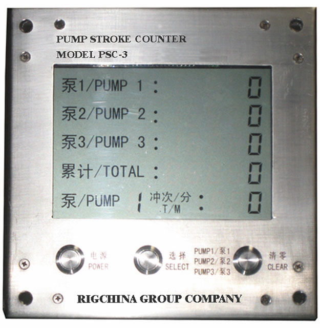
The RIGCHINA Pump Stroke Counter/Rate Meter displays both the total number of strokes and the strokes per minute for 3 mud pumps up to 1,024 strokes per minute for each pump. Push buttons conveniently located on the front of the instrument make it easy for the operator to reset each pump count

Measure and display the frequency of pump strokes of pump 1,and pump 2 and pump 3 by changing-over through the push- button of“select” on the panel.
material of the screw should be selected to use stainless steel. When a sensors installed on non-magnetic material, the material of the screw should be of iron quality.

1.The pumping sensor can be fixed to the mud pump head by the bracket, or the appropriate part of the turntable, and the closest distance between the position of the sensing surface of the measured object and the end surface of the sensor is within 30 mm. (According to the influence of the use environment, the rated working distance is generally taken. 80%), plus the working voltage, when the end of the inductive sports sensor is close, the indicator light is on; when away from the sensor, the indicator is off.
2.The turntable speed sensor can be fixed to the appropriate part of the drive shaft of the turntable with the bracket. It should be convenient to install and repair. The model of the drill is selected. A piece of iron with a length and width of 30mm is welded on the shaft of the drive shaft or the airbag clutch. The position of the end face should be close to the end face of the sensor. Adjust the fixing nut of the sensor so that the distance between the iron sensor is within the effective range of the working distance.

Our pump stroke counter systems (CPS101 Series) measure the stroke rate and number of strokes on mud pumps. The oilfield pump stroke system is user-friendly and reliable and is configurable to measure up to three mud pumps at once. Our digital pump stroke counter systems are manufactured here in the U.S. by Crown Oilfield Instrumentation, and Crown’s Pump Stroke Counter provides easy monitoring of strokes per minute on multiple mud pumps. Each mud pumps’s stroke rate can be selected individually and the display is updated regularly for accurate monitoring. LCD displays indicate both pumps strokes per minute and the total number of strokes. Located at the bottom of the panel, push buttons provide easy operation and reseting of each pump. When you need to accurately monitor and maintain the amount of mud being pumped, you can trust Crown’s oilfield stroke counters.

-Select-AfghanistanAlbaniaAlgeriaAmerican SamoaAndorraAngolaAnguillaAntigua and BarbudaArgentinaArmeniaArubaAustraliaAustriaAzerbaijan RepublicBahamasBahrainBangladeshBarbadosBelarusBelgiumBelizeBeninBermudaBhutanBoliviaBosnia and HerzegovinaBotswanaBrazilBritish Virgin IslandsBrunei DarussalamBulgariaBurkina FasoBurundiCambodiaCameroonCanadaCape Verde IslandsCayman IslandsCentral African RepublicChadChileChinaColombiaComorosCook IslandsCosta RicaCyprusCzech RepublicCôte d"Ivoire (Ivory Coast)Democratic Republic of the CongoDenmarkDjiboutiDominicaDominican RepublicEcuadorEgyptEl SalvadorEquatorial GuineaEritreaEstoniaEthiopiaFalkland Islands (Islas Malvinas)FijiFinlandFranceFrench GuianaFrench PolynesiaGabon RepublicGambiaGeorgiaGermanyGhanaGibraltarGreeceGreenlandGrenadaGuadeloupeGuamGuatemalaGuernseyGuineaGuinea-BissauGuyanaHaitiHondurasHong KongHungaryIcelandIndiaIndonesiaIraqIrelandIsraelItalyJamaicaJapanJerseyJordanKazakhstanKenyaKiribatiKuwaitKyrgyzstanLaosLatviaLebanonLesothoLiberiaLibyaLiechtensteinLithuaniaLuxembourgMacauMacedoniaMadagascarMalawiMalaysiaMaldivesMaliMaltaMarshall IslandsMartiniqueMauritaniaMauritiusMayotteMexicoMicronesiaMoldovaMonacoMongoliaMontenegroMontserratMoroccoMozambiqueNamibiaNauruNepalNetherlandsNetherlands AntillesNew CaledoniaNew ZealandNicaraguaNigerNigeriaNiueNorwayOmanPakistanPalauPanamaPapua New GuineaParaguayPeruPhilippinesPolandPortugalPuerto RicoQatarRepublic of CroatiaRepublic of the CongoReunionRomaniaRwandaSaint HelenaSaint Kitts-NevisSaint LuciaSaint Pierre and MiquelonSaint Vincent and the GrenadinesSan MarinoSaudi ArabiaSenegalSerbiaSeychellesSierra LeoneSingaporeSlovakiaSloveniaSolomon IslandsSomaliaSouth AfricaSouth KoreaSpainSri LankaSurinameSwazilandSwedenSwitzerlandTaiwanTajikistanTanzaniaThailandTogoTongaTrinidad and TobagoTunisiaTurkeyTurkmenistanTurks and Caicos IslandsTuvaluUgandaUnited Arab EmiratesUnited KingdomUnited StatesUruguayUzbekistanVanuatuVatican City StateVenezuelaVietnamVirgin Islands (U.S.)Wallis and FutunaWestern SaharaWestern SamoaYemenZambiaZimbabwe

The HDI 2100 Pump Stroke Counter is an intrinsically safe, certified, solid-state electronic stroke counter primarily used for monitoring mud pumps. Found most commonly within the HDI 9000 Choke Console System, the HDI 2100 monitors and displays the total accumulated mud pump strokes and the stroke rate of up to 4 individual mud pumps simultaneously. The stroke rate for each mud pump can be individually selected for display and is updated every second. Once installed, there is virtually no maintenance or calibration required. The quartz crystal oscillator provides high precision counts with no drift. The stainless steel case is completely sealed and features stainless steel piezo switches for long life. The entire package is constructed to operate in harsh environments and high vibration conditions encountered in land and offshore drilling. All HDI Gauges provide safety, accuracy, reliability, and low maintenance for the user.

During the drilling of an oil or gas well, backpressure control devices or “chokes” are used to impose backpressure on drilling fluid. Choke control panels may be used to monitor and/or control the imposition of backpressure by chokes. In some cases, choke control panels employ particularized and expensive gauges, which are not easily interchangeable. Additionally, some choke control panels or sensors and gauges thereof are dependent upon an external power source, such as a power source on a drilling rig. Still other choke control panels or gauges thereof do not provide sufficient incremental resolution of the values of different operation parameters, and/or are not operationally compatible with different types of chokes, such as both hydraulic and electric chokes. Therefore, what is needed is an apparatus, system or method that addresses one or more of the foregoing issues, among others.
In a first aspect, there is provided a system that includes a frame; a first digital display unit connected to the frame and capable of receiving digital information from each of a plurality of sensors, the first digital display unit including a first microcontroller to process digital information received from one or more sensors in the plurality of sensors; a first display in electrical communication with the first microcontroller; and a first switch in electrical communication with the first microcontroller so that, when the first microcontroller receives digital information from the one or more sensors in the plurality of sensors, the first microcontroller recognizes a first type of sensor from which the first microcontroller either is, or at least should be, receiving the digital information and displays a first output on the first display that is specific to the recognized first type of sensor; and a second digital display unit connected to the frame and capable of receiving digital information from each of the plurality of sensors, the second digital display unit including a second microcontroller to process digital information received from one or more other sensors in the plurality of sensors; a second display in electrical communication with the second microcontroller; and a second switch in electrical communication with the second microcontroller so that, when the second microcontroller receives the digital information from the one or more other sensors in the plurality of sensors, the second microcontroller recognizes a second type of sensor from which the second microcontroller either is, or at least should be, receiving the digital information; wherein the second type of sensor is different from the first type of sensor, the second switch is different from the first switch, and the second microcontroller displays a second output on the second display that is specific to the recognized second type of sensor and thus different from the first output.
In an exemplary embodiment, each of the first and second types of sensors is selected from the group consisting of a position sensor, a pressure sensor, and a stroke counter.
In another exemplary embodiment, the first type of sensor is a digital hydraulic choke position sensor, the second type of sensor is one of a digital pressure sensor and a digital stroke counter, and the frame and the first and second digital display units are part of a choke control panel.
In certain exemplary embodiments, the first output includes a value corresponding to the degree to which a hydraulic choke is open or closed; and wherein the second output includes one of a pressure value and a stroke rate.
In an exemplary embodiment, the system includes a digital hydraulic choke position sensor assembly adapted to determine the choke position of the hydraulic choke, the hydraulic choke including a rod, the digital hydraulic choke position sensor assembly being of the first type of sensor and including a housing adapted to be connected to the hydraulic choke, the housing defining a longitudinally-extending passage; and a digital position sensor disposed in the longitudinally-extending passage to sense movement of the rod and output digital information corresponding to the sensed movement; wherein the digital position sensor is adapted to be in electrical communication with the first microcontroller.
In another exemplary embodiment, the second type of sensor is the digital pressure sensor; and wherein the system further includes a digital pressure sensor assembly being of the second type of sensor, the digital pressure sensor assembly including a cover including first and second opposing end portions; a longitudinally-extending passage formed in the first end portion; a connector located at the second end portion and in electrical communication with the second microcontroller; and a pressure transducer adapted to be in electrical communication with the connector; and a plurality of components via which the pressure transducer is in electrical communication with the connector, wherein the components extend within the longitudinally-extending passage.
In an exemplary embodiment, the system includes the plurality of sensors; wherein first electrical power source is in electrical communication with the one or more sensors to supply electric power thereto; and wherein the second electrical power source is in electrical communication with the one or more other sensors to supply electrical power thereto.
In a second aspect, there is provided an apparatus capable of receiving digital information from each of a plurality of sensors, the apparatus including a first microcontroller to process digital information received from one or more sensors in the plurality of sensors; a first display in electrical communication with the first microcontroller; and a first switch in electrical communication with the first microcontroller so that, when the first microcontroller receives the digital information from the one or more sensors in the plurality of sensors, the first microcontroller recognizes a first type of sensor from which the first microcontroller either is, or at least should be, receiving the digital information and displays a first output on the first display that is specific to the recognized first type of sensor.
In an exemplary embodiment, the apparatus includes a first enclosure in which each of the first microcontroller and the first display are disposed; and a first electrical power source disposed in the first enclosure to supply electrical power to the first microcontroller and each of the one or more sensors.
In another exemplary embodiment, the first type of sensor is selected from the group consisting of a position sensor, a pressure sensor, and a stroke counter.
In certain exemplary embodiments, the first type of sensor is a digital hydraulic choke position sensor; and wherein the first output includes a value corresponding to the degree to which a hydraulic choke is open or closed.
In an exemplary embodiment, the first type of sensor is one of a pressure sensor and a stroke counter; and wherein the first output includes one of a pressure value and a stroke rate.
In certain exemplary embodiments, the apparatus includes a second lid assembly that is interchangeable with the first lid assembly so that, when the second lid assembly is interchanged with the first lid assembly, the second lid assembly is connected to the first enclosure instead of the first lid assembly being connected to the first enclosure; wherein the second lid assembly includes a second microcontroller to process digital information received from one or more other sensors in the plurality of sensors; a second display in electrical communication with the second microcontroller; and a second switch in electrical communication with the second microcontroller so that, when the second microcontroller receives the digital information from the one or more other sensors in the plurality of sensors, the second microcontroller recognizes a second type of sensor from which the second microcontroller either is, or at least should be, receiving the digital information and displays a second output on the second display that is specific to the recognized second type of sensor.
In a third aspect, there is provided an apparatus capable of receiving digital information from each of a plurality of sensors, the apparatus including a first enclosure; a first microcontroller disposed in the enclosure to process digital information received from one or more sensors in the plurality of sensors; a first display disposed in the enclosure and in electrical communication with the first microcontroller; and a first electrical power source disposed in the enclosure to supply electrical power to the first microcontroller and each of the one or more sensors.
In an exemplary embodiment, the apparatus includes a first switch in electrical communication with the first microcontroller so that, when the first microcontroller receives the digital information from the one or more sensors in the plurality of sensors, the first microcontroller recognizes a first type of sensor from which the first microcontroller either is, or at least should be, receiving the digital information and displays a first output on the first display that is specific to the recognized first type of sensor.
In another exemplary embodiment, the first type of sensor is selected from the group consisting of a position sensor, a pressure sensor, and a stroke counter.
In certain exemplary embodiments, the first type of sensor is a digital hydraulic choke position sensor; and wherein the first output includes a value corresponding to the degree to which a hydraulic choke is open or closed.
In an exemplary embodiment, the first type of sensor is one of a pressure sensor and a stroke counter; and wherein the first output includes one of a pressure value and a stroke rate.
In certain exemplary embodiments, the apparatus includes a second lid assembly that is interchangeable with the first lid assembly so that, when the second lid assembly is interchanged with the first lid assembly, the second lid assembly is connected to the first enclosure instead of the first lid assembly being connected to the first enclosure; wherein the second lid assembly includes a second microcontroller to process digital information received from one or more other sensors in the plurality of sensors; a second display in electrical communication with the second microcontroller; and a second switch in electrical communication with the second microcontroller so that, when the second microcontroller receives the digital information from the one or more other sensors in the plurality of sensors, the second microcontroller recognizes a second type of sensor from which the second microcontroller either is, or at least should be, receiving the digital information and displays a second output on the second display that is specific to the recognized second type of sensor.
In a fourth aspect, there is provided a kit including a plurality of enclosures; and a plurality of lid assemblies, each lid assembly in the plurality of lid assemblies being connectable to each enclosure in the plurality of enclosures; wherein each lid assembly includes a microcontroller capable of receiving and processing digital information from each sensor in a plurality of sensors; and a display in electrical communication with the microcontroller; wherein the respective microcontrollers of the lid assemblies are identical to one another; wherein each lid assembly includes a switch in electrical communication with the corresponding microcontroller of the lid assembly; and wherein each one of the switches is different from the other switches so that, when the lid assemblies are connected to the enclosures, respectively, and each of the microcontrollers receives digital information from one or more sensors in the plurality of sensors: at least one of the switches causes the corresponding microcontroller to recognize a first type of sensor from which the microcontroller either is, or at least should be, receiving the digital information and displays a first output on the corresponding display that is specific to the recognized first type of sensor; and at least one other of the switches causes the corresponding microcontroller to recognize a second type of sensor from which the microcontroller either is, or at least should be, receiving the digital information and displays a second output on the corresponding display that is specific to the recognized second type of sensor.
In an exemplary embodiment, the second type of sensor is different from the first type of sensor, the second switch is different from the first switch, and the second output is different from the first output.
In another exemplary embodiment, each of the first and second types of sensors is selected from the group consisting of a position sensor, a pressure sensor, and a stroke counter.
In certain exemplary embodiments, the first type of sensor is a digital hydraulic choke position sensor, the second type of sensor is one of a digital pressure sensor and a digital stroke counter, and the frame and the first and second digital display units are part of a choke control panel.
In an exemplary embodiment, the first output includes a value corresponding to the degree to which a hydraulic choke is open or closed; and wherein the second output includes one of a pressure value and a stroke rate.
In another exemplary embodiment, the kit includes a digital hydraulic choke position sensor assembly adapted to determine the choke position of the hydraulic choke, the hydraulic choke including a rod, the digital hydraulic choke position sensor assembly being of the first type of sensor and including: a housing adapted to be connected to the hydraulic choke, the housing defining a longitudinally-extending passage; and a digital position sensor disposed in the longitudinally-extending passage to sense movement of the rod and output digital information corresponding to the sensed movement; wherein the digital position sensor is adapted to be in electrical communication with one of the microcontrollers.
In certain exemplary embodiments, the second type of sensor is the digital pressure sensor; and wherein the kit further includes a digital pressure sensor assembly being of the second type of sensor, the digital pressure sensor assembly including a cover including first and second opposing end portions; a longitudinally-extending passage formed in the first end portion; a connector located at the second end portion and adapted to be in electrical communication with one of the microcontrollers; a pressure transducer in electrical communication with the connector; and a plurality of components via which the pressure transducer is in electrical communication with the connector, wherein the components extend within the longitudinally-extending passage.
In a fifth aspect, there is provided a digital hydraulic choke position sensor assembly adapted to determine the choke position of a hydraulic choke, the hydraulic choke including a first rod, the digital hydraulic choke position sensor assembly including a housing adapted to be connected to the hydraulic choke, the housing defining a longitudinally-extending passage; and a digital position sensor disposed in the longitudinally-extending passage to sense movement of the first rod and output digital information corresponding to the sensed movement.
In an exemplary embodiment, the digital hydraulic choke position sensor assembly includes an actuator button connected to the digital position sensor and adapted to engage the first rod of the hydraulic choke; and a connector assembly in electrical communication with the digital position sensor.
In certain exemplary embodiments, the digital position sensor includes a tubular enclosure, a second rod extending in, and movable relative to, the tubular enclosure, and a cable assembly extending between the tubular enclosure and the connector assembly; and wherein the actuator button is connected to the distal end of the second rod.
In another exemplary embodiment, the actuator button includes an external shoulder; wherein the longitudinally-extending passage defines an internal surface of the housing; wherein the digital hydraulic choke position sensor assembly further includes a compression spring through which at least the second rod extends; and wherein the compression spring extends between the external shoulder of the actuator button and the internal surface of the housing so that the compression spring is compressed when the actuator button moves towards the internal surface.
In certain exemplary embodiments, the digital hydraulic choke position sensor assembly includes a plurality of fasteners to hold the digital position sensor in place within the longitudinally-extending passage.
In a sixth aspect, there is provided a digital pressure sensor assembly that includes a cover including first and second opposing end portions; a longitudinally-extending passage formed in the first end portion; a connector located at the second end portion; a pressure transducer in electrical communication with the connector; and a plurality of components via which the pressure transducer is in electrical communication with the connector, wherein the components extend within the longitudinally-extending passage.
In another exemplary embodiment, the digital pressure sensor assembly includes a base connected to the cover at the first end portion thereof; and a first bore formed through the base and in which the pressure transducer is disposed.
In certain exemplary embodiments, the digital pressure sensor assembly includes a region formed in the second end portion of the cover and defining an axially-facing surface of the cover; and a second bore formed through the axially-facing surface of the cover so that the region is in fluid communication with the longitudinally-extending passage; wherein the connector is connected to the axially-facing surface and at least a portion of the connector is disposed in the second bore.
In another exemplary embodiment, the digital pressure sensor assembly includes a nut connected to the base; wherein the first bore defines an internal shoulder; and wherein the pressure transducer is captured between the nut and the internal shoulder.
FIG. 2 is a diagrammatic illustration of a portion of a system for drilling an oil or gas well according to an exemplary embodiment, and the system includes the choke control panel of FIG. 1 and a plurality of sensors.
FIG. 4 is a diagrammatic illustration of a portion of the digital display unit of FIGS. 1 and 4 according to an exemplary embodiment, and the portion of the digital display unit is in electrical communication with two of the sensors of FIG. 2.
In an exemplary embodiment, as illustrated in FIG. 1, a control panel, or a choke control panel, for a hydraulic choke system is generally referred to by the reference numeral 10 and includes a frame 12 to which digital display units 14, 16, 18 and 20, and hydraulic control equipment 22, are connected. The frame 12 includes a pivotally-mounted cover 12 a, which pivots between an open position (shown in FIG. 1) and a closed position in which the digital display units 14, 16, 18 and 20 are covered (not shown). The hydraulic control equipment 22 includes at least one control lever, such as a joystick 22 a. In several exemplary embodiments, the hydraulic control equipment 22 includes one or more hydraulic pumps, one or more air-operated hydraulic pumps, one or more manually-operated hydraulic pumps, one or more hydraulic reservoir assemblies, one or more hydraulic hoses, and tubing. In several exemplary embodiments, the hydraulic control equipment 22 includes conventional hydraulic control equipment used to control one or more hydraulic chokes, which may be part of a system for drilling an oil or gas well. In several exemplary embodiments, the choke control panel 10 may be characterized as either a remote operating console or a choke control console.
Referring to FIG. 2 with continuing reference to FIG. 1, illustrated is a diagrammatic view of a portion of a system 24 for drilling an oil or gas well. The system 24 includes the choke control panel 10. Hydraulic chokes 26 and 28 are operably coupled to the hydraulic control equipment 22. In several exemplary embodiments, each of the hydraulic chokes 26 and 28 is in fluid communication with one or more components of the hydraulic control equipment 22. Digital hydraulic choke position sensors 30 and 32 are operably coupled to the hydraulic chokes 26 and 28, respectively. Under conditions to be described below, the digital hydraulic choke positions sensors 30 and 32 are adapted to measure the degree to which the hydraulic chokes 26 and 28 are open or closed, respectively. In an exemplary embodiment, the digital hydraulic choke position sensor 30 is in electrical communication with the digital display unit 14 via cable assemblies 34 and 36, and the digital hydraulic choke position sensor 32 is in electrical communication with the digital display unit 14 via a cable assembly 38 and the cable assembly 36. In an exemplary embodiment, the cable assemblies 34 and 38 connect to the cable assembly 36 via a two-to-one connector or a Y connector, which connector may be mounted within, or outside of, the frame 12.
Digital stroke sensors or counters 40 and 42 are in electrical communication with the digital display unit 20. In an exemplary embodiment, the digital stroke counter 40 is in electrical communication with the digital display unit 20 unit via cable assemblies 44 and 46, and the digital stroke counter 42 is in electrical communication with the digital display unit 20 via a cable assembly 48 and the cable assembly 46. In an exemplary embodiment, the cable assemblies 44 and 48 connect to the cable assembly 46 via a two-to-one connector or a Y connector, which connector may be mounted outside of, or within, the frame 12. The digital stroke counters 40 and 42 are operably coupled to pumps 50 and 52, respectively. In an exemplary embodiment, each of the pumps 50 and 52 is a positive displacement drilling fluid (or mud) pump, which facilitates the circulation of drilling fluid or mud down through a drilling or casing string that extends within a wellbore, and up through an annular region defined between the wellbore and the drilling or casing string. Under conditions to be described below, the digital stroke counters 40 and 42 are adapted to provide an indication of fluid flow rate out of the pumps 50 and 52, respectively.
Digital pressure sensors 54 and 56 are in electrical communication with the digital display units 16 and 18, respectively. In an exemplary embodiment, the digital pressure sensors 54 and 56 are in electrical communication with the digital display units 16 and 18, respectively, via cable assemblies 58 and 60, respectively. The digital pressure sensor 54 is operably coupled to a standpipe 62, and the digital pressure sensor 56 is operably coupled to casing 64. Under conditions to be described below, the digital pressure sensors 54 and 56 are adapted to measure respective pressures at the standpipe 62 and the casing 64.
As shown in FIGS. 4 and 5, the connector assembly 78 is in electrical communication with the connector 100 via a cable assembly 104 and a connector 105. In an exemplary embodiment, the connector assembly 78 and the connector 105 may be characterized as part of the cable assembly 104. Although not shown in FIG. 3, the cable assembly 104 and the connector 105 are disposed within the enclosure 74, extending from the connector assembly 78 to the connector 100 on the printed circuit board 90. A connector 106 is connected to, and in electrical communication with, the connector assembly 78. In an exemplary embodiment, the connector 106 is coupled to a cable mounting plate (not shown), which is connected to the frame 12. In an exemplary embodiment, the connector 106, the connector assembly 78, and the cable assembly 104 are part of the cable assembly 36, which is shown in FIG. 2. Therefore, each of the digital hydraulic choke position sensors 30 and 32 is in electrical communication with the microcontroller 94 via the connector 106, the connector assembly 78, the cable assembly 104, the connector 100, and the printed circuit board 90.
As shown in FIGS. 4 and 6, the batteries 76 aand 76 bare in electrical communication with a connector 112 via the respective battery holders 70 aand 70 band a cable assembly 114. The connector 112 and the cable assembly 114 are disposed within the enclosure 74. In an exemplary embodiment, the connector 112 may be characterized as part of the cable assembly 114. As shown in FIG. 4, the connector 112 is connected to, and in electrical communication with, the connector 98. Under conditions to be described below, the batteries 76 aand 76 bare adapted to supply electrical power to the electrical components on the printed circuit board 90, including the microcontroller 94. The batteries 76 aand 76 bsupply electrical power to such components via the respective holders 70 aand 70 b, the cable assembly 114, the connector 112, the connector 98, and the printed circuit board 90. Additionally, the batteries 76 aand 76 bare adapted to supply electrical power to the digital hydraulic choke position sensors 30 and 32. The batteries 76 aand 76 bsupply electrical power to the digital hydraulic choke position sensors 30 and 32 via the respective holders 70 aand 70 b, the cable assembly 114, the connector 112, the connector 98, the printed circuit board 90, the connector 100, the cable assembly 104, the connector 78, the connector 106, the cable assembly 36, and the respective cable assemblies 34 and 38.
In an exemplary embodiment, as illustrated in FIGS. 9A and 9B with continuing reference to FIGS. 1-8, the graphic overlay 126 indicates choke position of two chokes. The connector 108 is a tail connector having a pin #1. The connector 108 extends generally horizontally through the slot 124 a. Referring to FIG. 10, illustrated is a diagrammatic view of a switch schematic 140 of the switch 110. As noted above, in an exemplary embodiment, the connector 102 is a flexible printed circuit (FPC) connector, with which the connector 108 is in electrical communication when the overlay assembly 122 is connected to the lid 120. Under conditions to be described below, the switch 110 electrically communicates with the microcontroller 94, via the connector 108, the connector 102 and the printed circuit board 90, so that the microcontroller 94 recognizes the type of sensor from which it is (or at least should be) receiving digital information (i.e., a position sensor such as the digital hydraulic choke position sensors 30 and 32) and, based on that sensor type, accordingly processes the digital information and displays relevant output specific to that sensor type on one or more of the displays 96 a, 96 b, 96 cand 96 d.
In an exemplary embodiment, the digital display unit 16 includes components that are identical to corresponding components of the digital display unit 14 described above. These identical components will be referred to by the same reference numerals, followed by the phrase “of the digital display unit 16”. The digital display unit 16 differs from the digital display unit 14 in two respects. First, instead of being in electrical communication with the digital hydraulic choke position sensors 30 and 32, the connector 78 of the digital display unit 16 is in electrical communication with the digital pressure sensor 54, as shown in FIG. 2. The second difference is that the digital display unit 16 does not include an overlay assembly that is identical to the overlay assembly 122 of the digital display unit 14. Instead, the digital display unit 16 includes an overlay assembly 142, an exemplary embodiment of which is illustrated in FIG. 11 and described in further detail below.
In an exemplary embodiment, as illustrated in FIGS. 12A and 12B with continuing reference to FIGS. 1-11, the graphic overlay 144 of the digital display unit 16 indicates a pressure measurement and thus is different from the graphic overlay of the digital unit display 14, which indicates choke position. The connector 156 is a tail connector having a pin #1. The connector 156 extends generally horizontally through the slot 162 a. Referring to FIG. 13, illustrated is a diagrammatic view of a switch schematic 164 of the switch 154. The switch 154 is different from the switch 110, as indicated by a comparison between the switch schematic 140 shown in FIG. 10 and the switch schematic 164 shown in FIG. 13. In an exemplary embodiment, the connector 102 of the digital display unit 16 is a flexible printed circuit (FPC) connector, with which the connector 156 is in electrical communication when the overlay assembly 142 is connected to the lid 120 of the digital display unit 16. Under conditions to be described below, the switch 154 electrically communicates with the microcontroller 94 of the digital display unit 16, via the connector 156, the connector 102 of the digital display unit 16, and the printed circuit board 90 of the digital display unit 16, so that the microcontroller 94 of the digital display unit 16 recognizes the type of sensor from which it is (or at least should be) receiving digital information (i.e., a pressure sensor such as the digital pressure sensor 54) and, based on that sensor type, accordingly processes the digital information and displays relevant output specific to that sensor type on one or more of the displays 96 a, 96 b, 96 cand 96 dof the digital display unit 16.
In an exemplary embodiment, the digital display unit 18 is identical to the digital display unit 16 and therefore will not be described in detail. Instead of being in electrical communication with the digital pressure sensor 54, the connector 78 of the digital display unit 18 is in electrical communication with the digital pressure sensor 56, as shown in FIG. 2. In an exemplary embodiment, the connector assembly 78 of the digital display unit 18 is in electrical communication with yet another connector (not shown) that is equivalent to the connector 106 (shown in FIG. 4), which other connector may be coupled to a cable mounting plate (not shown) that is connected to the frame 12.
In an exemplary embodiment, the digital display unit 20 includes components that are identical to corresponding components of the digital display unit 14 described above. These identical components will be referred to by the same reference numerals, followed by the phrase “of the digital display unit 20”. The digital display unit 20 differs from the digital display unit 14 in two respects. First, instead of being in electrical communication with the digital hydraulic choke position sensors 30 and 32, the connector 78 of the digital display unit 20 is in electrical communication with each of the digital stroke counters 40 and 42, as shown in FIG. 2. The second difference is that the digital display unit 20 does not include an overlay assembly that is identical to the overlay assembly 122 of the digital display unit 14. Instead, the digital display unit 16 includes an overlay assembly 166, an exemplary embodiment of which is illustrated in FIG. 14 and described in further detail below.
In an exemplary embodiment, as illustrated in FIGS. 15A and 15B with continuing reference to FIGS. 1-14, the graphic overlay 168 of the digital display unit 20 indicates stroke count and total strokes, and thus is different from the graphic overlay of the digital unit display 14, which indicates choke position. The connector 180 is a tail connector having a pin #1. The connector 180 extends generally horizontally through the slot 162 a. Referring to FIG. 16, illustrated is a diagrammatic view of a switch schematic 188 of the switch 178. The switch 178 is different from each of the switches 110 and 154, as indicated by a comparison between the switch schematic 140 shown in FIG. 10, the switch schematic 164 shown in FIG. 13, and the switch schematic 188 shown in FIG. 16. In an exemplary embodiment, the connector 102 of the digital display unit 20 is a flexible printed circuit (FPC) connector, with which the connector 180 is in electrical communication when the overlay assembly 166 is connected to the lid 120 of the digital display unit 20. Under conditions to be described below, the switch 178 electrically communicates with the microcontroller 94 of the digital display unit 20, via the connector 180, the connector 102 of the digital display unit 20, and the printed circuit board 90 of the digital display unit 20, so that the microcontroller 94 of the digital display unit 20 recognizes the type of sensor from which it is (or at least should be) receiving digital information (i.e., a stroke counter such as the digital stroke counters 40 and 42) and, based on that sensor type, accordingly processes the digital information and displays relevant output specific to that sensor type on one or more of the displays 96 a, 96 b, 96 cand 96 dof the digital display unit 20.
As indicated above, each of the digital display units 14, 16, 18 and 20 includes a respective combination of the connector assembly 78, the cable assembly 104, and the connector 105; thus, any one of the respective combinations can receive (and transmit) digital information to the corresponding printed circuit board 90 from (or to) any of the sensors, namely the digital hydraulic choke position sensors 30 and 32, the digital stroke counters 40 and 42, the digital pressure sensor 54, or the digital pressure sensor 56. However, the manner in which the corresponding microcontroller 94 processes the received digital information and displays relevant output depends upon which of the switches 110, 154 and 178 is in electrical communication with the microcontroller 94. Additionally, any one combination of the connector assembly 78, the cable assembly 104, and the connector 105 can be used to supply electrical power from the corresponding batteries 76 aand 76 bto the digital hydraulic choke position sensors 30 and 32, the digital stroke counters 40 and 42, the digital pressure sensor 54, or the digital pressure sensor 56. In an exemplary embodiment, each of the connector assembly 78 and the connector 105 may have fourteen pins, two of which are associated with the digital hydraulic choke position sensor 30, two of which are associated with the digital hydraulic choke position sensor 32, three of which are associated with the digital stroke counter 40, three of which are associated with the digital stroke counter 42, and four of which are associated with the digital pressure sensors 54 and 56.
In an exemplary embodiment, during the operation of the system 24, one or both of the pumps 50 and 52 facilitate the circulation of drilling fluid or mud down through a drilling or casing string that extends within a wellbore, and up through an annular region defined between the wellbore and the drilling or casing string. One or both of the hydraulic chokes 26 and 28 may be opened and/or closed to control the imposition of backpressure on the drilling fluid. In several exemplary embodiments, one or both of the hydraulic chokes 26 and 28 may be controlled by opening and/or closing the hydraulic chokes 26 and 28 using the hydraulic control equipment 22 of the choke control panel 10, including the joystick 22 a. This control of the hydraulic chokes 26 and 28 may be informed by monitoring, using the choke control panel 10, one or more operation parameters including, but not limited to, the respective stroke counts (and thus flow rate indications) of the pumps 50 and 52, the pressure at the standpipe 62, the pressure at the casing 64, and the respective choke positions of the hydraulic chokes 26 and 28.
In an exemplary embodiment, to monitor the respective choke positions of the hydraulic chokes 26 and 28, the digital hydraulic choke position sensors 30 and 32 sense the degree to which the hydraulic chokes 26 and 28 are open or closed, and then transmit digital readings or information corresponding to the sensed open/closed degrees to the digital display unit 14. The digital hydraulic choke position sensor 30 transmits the digital information to the digital display unit 14 via the cable assemblies 34 and 36. The digital hydraulic choke position sensor 32 transmits the digital information to the digital display unit 14 via the cable assemblies 38 and 36. At the digital display unit 14, the digital information from the digital hydraulic choke position sensors 30 and 32 is transmitted to the microcontroller 94 of the digital display unit 14 via the connector 106, and the connector assembly 78, the cable assembly 104, the connector 105, the connector 100, and the printed circuit board 90 of the digital display unit 14. The switch 110 electrically communicates with the microcontroller 94 of the digital display unit 14, via the connector 108, the connector 102 and the printed circuit board 90 of the digital display unit 14, so that the microcontroller 94 of the digital display unit 14 recognizes the type of sensor from which it is (or at least should be) receiving digital information, namely a position sensor, such as the digital hydraulic choke position sensors 30 and 32. Based on this recognition, the microcontroller 94 accordingly processes the digital information and outputs relevant digital output specific to that sensor type on one or more of the displays 96 a, 96 b, 96 cand 96 dof the digital display unit 14. In an exemplary embodiment, the microcontroller 94 of the digital display unit 14 may output one or more values corresponding to the degree to which the hydraulic chokes 26 and 28 are open or closed; such values include, for example, the percentage that the hydraulic choke 26 is open on the display 96 aof the digital display unit 14, a number indicating the degree to which the hydraulic choke 26 is open on the display 96 cof the digital display unit 14, the percentage that the hydraulic choke 28 is open on the display 96 bof the digital display unit 14, and a number indicating the degree to which the hydraulic choke 26 is open on the display 96 dof the digital display unit 14.
Before, during and/or after the transmission of digital information to the digital display unit 14, the batteries 76 aand 76 bof the digital display unit 14 supply electrical power to the electrical components on the printed circuit board 90 of the digital display unit 14, including the microcontroller 94. The batteries 76 aand 76 bof the digital display unit 14 supply electrical power to such components via the respective holders 70 aand 70 b, the cable assembly 114, the connector 112, the connector 98, and the printed circuit board 90 of the digital display unit 14. Additionally, before, during and/or after the transmission of digital information to the digital display unit 14, the batteries 76 aand 76 bof the digital display unit 14 supply electrical power to the digital hydraulic choke position sensors 30 and 32 via the respective holders 70 aand 70 b, the cable assembly 114, the connector 112, the connector 98, the printed circuit board 90, the connector 100, the cable assembly 104, and the connector 78 of the digital display unit 14, as well as the connector 106, the cable assembly 36, and the respective cable assemblies 34 and 38.
In an exemplary embodiment, to monitor the pressure at the standpipe 62, the digital pressure sensor 54 senses the pressure at the standpipe 62, and then transmits digital readings or information corresponding to the sensed pressure to the digital display unit 16. The digital pressure sensor 54 transmits the digital information to the digital display unit 16 via the cable assembly 58. At the digital display unit 16, the digital information from the digital pressure sensor 54 is transmitted to the microcontroller 94 of the digital display unit 16 via a connector that is equivalent to the connector 106, and also via the connector assembly 78, the cable assembly 104, the connector 105, the connector 100, and the printed circuit board 90 of the digital display unit 16. The switch 154 electrically communicates with the microcontroller 94 of the digital display unit 16, via the connector 108, the connector 102 and the printed circuit board 90 of the digital display unit 16, so that the microcontroller 94 of the digital display unit 16 recognizes the type of sensor from which it is (or at least should be) receiving digital information, namely a pressure sensor, such as the digital pressure sensor 54. Based on this recognition, the microcontroller 94 accordingly processes the digital information and outputs relevant digital output specific to that sensor type on one or more of the displays 96 a, 96 b, 96 cand 96 dof the digital display unit 16. In an exemplary embodiment, the microcontroller 94 of the digital display unit 16 may output, for example, the pressure value at the standpipe 62 on one or both of the displays 96 aand 96 bof the digital display unit 16.
Before, during and/or after the transmission of digital information to the digital display unit 16, the batteries 76 aand 76 bof the digital display unit 16 supply electrical power to the electrical components on the printed circuit board 90 of the digital display unit 16, including the microcontroller 94. The batteries 76 aand 76 bof the digital display unit 16 supply electrical power to such components via the respective holders 70 aand 70 b, the cable assembly 114, the connector 112, the connector 98, and the printed circuit board 90 of the digital display unit 16. Additionally, before, during and/or after the transmission of digital information to the digital display unit 16, the batteries 76 aand 76 bof the digital display unit 16 supply electrical power to the digital pressure sensor 54 via the respective holders 70 aand 70 b, the cable assembly 114, the connector 112, the connector 98, the printed circuit board 90, the connector 100, the cable assembly 104, and the connector 78 of the digital display unit 16, as well as a connector that is equivalent to the connector 106, and the cable assembly 58.
In an exemplary embodiment, to monitor the pressure at the casing 64, the digital pressure sensor 56 senses the pressure at the casing 64, and then transmits digital readings or information corresponding to the sensed pressure to the digital display unit 18. The digital pressure sensor 56 transmits the digital information to the digital display unit 18 via the cable assembly 60. At the digital display unit 18, the digital information from the digital pressure sensor 56 is transmitted to the microcontroller 94 of the digital display unit 18 via a connector that is equivalent to the connector 106, and also via the connector assembly 78, the cable assembly 104, the connector 105, the connector 100, and the printed circuit board 90 of the digital display unit 18. The switch 178 electrically communicates with the microcontroller 94 of the digital display unit 18, via the connector 108, the connector 102 and the printed circuit board 90 of the digital display unit 18, so that the microcontroller 94 of the digital display unit 16 recognizes the type of sensor from which it is (or at least should be) receiving digital information, namely a pressure sensor, such as the digital pressure sensor 56. Based on this recognition, the microcontroller 94 accordingly processes the digital information and outputs relevant digital output specific to that sensor type on one or more of the displays 96 a, 96 b, 96 cand 96 dof the digital display unit 18. In an exemplary embodiment, the microcontroller 94 of the digital display unit 18 may output, for example, a pressure value at the casing 64 on one or both of the displays 96 aand 96 bof the digital display unit 18.
Before, during and/or after the transmission of digital information to the digital display unit 18, the batteries 76 aand 76 bof the digital display unit 18 supply electrical power to the electrical components on the printed circuit board 90 of the digital display unit 18, including the microcontroller 94. The batteries 76 aand 76 bof the digital display unit 18 supply electrical power to such components via the respective holders 70 aand 70 b, the cable assembly 114, the connector 112, the connector 98, and the printed circuit board 90 of the digital display unit 18. Additionally, before, during and/or after the transmission of digital information to the digital display unit 18, the batteries 76 aand 76 bof the digital display unit 18 supply electrical power to the digital pressure sensor 56 via the respective holders 70 aand 70 b, the cable assembly 114, the connector 112, the connector 98, the printed circuit board 90, the connector 100, the cable assembly 104, and the connector 78 of the digital display unit 18, as well as a connector that is equivalent to the connector 106, and the cable assembly 60.
In an exemplary embodiment, to monitor the respective stroke counts (and thus flow rate indications) of the pumps 50 and 52, the digital stroke counters 40 and 42 sense the respective strokes of the pumps 50 and 52, and then transmit digital readings or information corresponding to the sensed strokes to the digital display unit 20. The digital stroke counter 40 transmits the digital information to the digital display unit 20 via the cable assemblies 44 and 46. The digital stroke counter 42 transmits the digital information to the digital display unit 20 via the cable assemblies 48 and 46. At the digital display unit 20, the digital information from the digital stroke counters 40 and 42 is transmitted to the microcontroller 94 of the digital display unit 20 via a connector that is equivalent to the connector 106, and the connector assembly 78, the cable assembly 104, the connector 105, the connector 100, and the printed circuit board 90 of the digital display unit 20. The switch 178 electrically communicates with the microcontroller 94 of the digital display unit 20, via the connector 108, the connector 102 and the printed circuit board 90 of the digital display unit 20, so that the microcontroller 94 of the digital display unit 20 recognizes the type of sensor from which it is (or at least should be) receiving digital information, namely a stroke counter, such as the digital stroke counters 40 and 42. Based on this recognition, the microcontroller 94 accordingly processes the digital information and outputs relevant digital output specific to that sensor type on one or more of the displays 96 a, 96 b, 96 cand 96 dof the digital display unit 20. In an exemplary embodiment, the microcontroller 94 of the digital display unit 20 may output, for example, a stroke rate such as the strokes per minute of the pump 50 on the display 96 aof the digital display unit 20, the total strokes of the pump 50 on the display 96 cof the digital display unit 20, a stroke rate such as the strokes per minute of the pump 52 on the display 96 bof the digital display unit 20, and the total strokes of the pump 52 on the display 96 dof the digital display unit 20.
Before, during and/or after the transmission of digital information to the digital display unit 20, the batteries 76 aand 76 bof the digital display unit 20 supply electrical power to the electrical components on the printed circuit board 90 of the digital display unit 20, including the microcontroller 94. The batteries 76 aand 76 bof the digital display unit 20 supply electrical power to such components via the respective holders 70 aand 70 b, the cable assembly 114, the connector 112, the connector 98, and the printed circuit board 90 of the digital display unit 20. Additionally, before, during and/or after the transmission of digital information to the digital display unit 20, the batteries 76 aand 76 bof the digital display unit 20 supply electrical power to the digital stroke counters 40 and 42 via the respective holders 70 aand 70 b, the cable assembly 114, the connector 112, the connector 98, the printed circuit board 90, the connector 100, the cable assembly 104, and the connector 78 of the digital display unit 20, as well as a connector that is equivalent to the connector 106, the cable assembly 46, and the respective cable assemblies 44 and 48.
As indicated above, each of the digital display units 14, 16, 18 and 20 includes a respective combination of the connector assembly 78, the cable assembly 104, and the connector 105; thus, any one of the respective combinations can receive and transmit digital information to the corresponding printed circuit board 90 from the digital hydraulic choke position sensors 30 and 32, the digital stroke counters 40 and 42, the digital pressure sensor 54, or the digital pressure sensor 56. However, the manner in which the corresponding microcontroller 94 processes the received digital information and displays relevant output depends upon which of the switches 110, 154 and 178 is in electrical communication with the microcontroller 94. Additionally, any one combination of the connector assembly 78, the cable assembly 104, and the connector 105 can be used to supply electrical power from the corresponding batteries 76 aand 76 bto the digital hydraulic choke position sensors 30 and 32, the digital stroke counters 40 and 42, the digital pressure sensor 54, or the digital pressure sensor 56.
In view of the foregoing, in an exemplary embodiment, the ability of each of the digital display units 14, 16, 18 or 20 to supply electrical power to the sensor(s) with which it is in electrical communication (the sensors 30 and 32, the sensor 54, the sensor 56, or the sensors or counters 40 and 42) eliminates the susceptibility of the choke control panel 10 to power losses from another source, such as a drilling rig that is part of the system 24. In other words, the choke control panel 10 may be operated without being dependent upon the supply of electrical power from the drilling rig. The choke control panel 10 operates independently of other electrical power sources. Additionally, the sensors 30 and 32, the sensor 54, the sensor 56, and the counters 40 and 42 operate with their own respective electrical power sources (i.e., the batteries 76 aand 76 bof the corresponding digital display unit 14, 16, 18 and 20), independently of the other electrical powers sources in the choke control panel 10.
In an exemplary embodiment, as illustrated in FIGS. 17, 18 and 19 with continuing reference to FIGS. 1-16, the digital hydraulic choke position sensor 30 is an assembly that includes a housing 194 and a sleeve 196 connected thereto. An end portion 194 aof the housing 194 extends within the sleeve 196, and an opposing end portion 194 bincludes a flange 194 c. A region 200 is formed in the end portion 194 a, defining an axially-facing surface 194 dof the housing 194. Radially-extending bores 202 aand 202 bare formed through the housing 194 adjacent the region 200. A longitudinally-extending passage 204 is defined by the housing 194. The passage 204 includes a reduced-diameter portion 204 aadjacent the region 200, and an enlarged-diameter portion 204 bthat extends from the reduced-diameter portion 204 ato the end portion 194 b. Radially-extending bores 206 aand 206 bare formed through the housing 194 adjacent the reduced-diameter portion 204 a.
A digital position sensor 208 extends within the longitudinally-extending passage 204 defined by the housing 194. In an exemplary embodiment, the digital position sensor 208 is, includes, or is part of, a linear potentiometer. In an exemplary embodiment, the digital position sensor 208 is, includes, or is part of, an Omega® LP803-02 linear potentiometer. In an exemplary embodiment, the digital position sensor 208 includes a tubular enclosure 208 aand a rod 208 bextending therein. The rod 208 bis movable relative to the tubular enclosure 208 a. Respective portions of the tubular enclosure 208 aand the rod 208 bextend through a compression spring 210.
An actuator button 212 is connected to the distal end of the rod 208 band includes an external shoulder 212 a. In an exemplary embodiment, the actuator button 212 is connected to the distal end portion of the rod 208 bvia a threaded engagement with an external threaded connection 208 cat the distal end portion of the rod 208 b. The compression spring 210 extends between the external shoulder 212 aand a frusto-conical transition internal surface 194 eof the housing 194, which internal surface extends between the portions 204 aand 204 bof the passage 204. As shown in FIG. 19, a connector assembly 214 is in electrical communication with the digital position sensor 208 via a cable assembly 216 (the cable assembly 16 is not shown in FIG. 18). In an exemplary embodiment, the connector assembly 214 may be characterized as part of the cable assembly 216, and/or the connector assembly 214 and the cable assembly 216 may be characterized as part of the digital position sensor 208. As shown in FIG. 18, the connector assembly 214 is connected to the axially-facing surface 194 d. Although not shown in FIG. 18, the cable assembly 216 is disposed in the reduced-diameter portion 204 aof the passage 204. The connector assembly 214 is connected to, and in electrical communication with, the cable assembly 34, as indicated in FIG. 2.
As shown in FIG. 18, the sleeve 196 includes radially-extending bores 196 aand 196 b, which are concentric with the radially-extending bores 206 aand 206 b, respectively. Set screws 218 aand 218 bare positioned in the radially-extending bores 206 aand 206 b, respectively, and engage the tubular enclosure 208 a, holding the digital position sensor 208 in place within the longitudinally-extending passage 204. Fasteners, such as cap screws 220 aand 220 b, extend through the bores 196 aand 196 b, respectively, and into the bores 206 aand 206 b, respectively. The cap screws 220 aand 220 bconnect the sleeve 196 to the housing 194 and hold in place the set screws 218 aand 218 b, respectively, thereby ensuring that the digital position sensor 208 is held in place by the set screws 218 aand 218 b.
In operation, in an exemplary embodiment, as the hydraulic choke 26 is opened using the hydraulic control equipment 22, the actuator rod 26 amoves to the right, as viewed in FIG. 18, causing the actuator button 212 to also move to the right, as viewed in FIG. 18. As a result, the spring 210 is compressed, the rod 208 bmoves relative to the tubular enclosure 208 a, and the movement of the rod 208 bis sensed by the digital position sensor 208. In response, the digital position sensor 208 transmits or outputs digital information corresponding to the sensed movement to the digital display unit 14 via the cable assembly 216, the connector assembly 214, and the cable assemblies 34 and 36, in accordance with the foregoing. As the hydraulic choke 26 is closed using the hydraulic control equipment 22, the actuator rod 26 amoves to the left, as viewed in FIG. 18. As a result, the spring 210 decompresses, pushing the actuator button 212 and thus the rod 208 b, relative to the tubular enclosure 208 aand to the left, as viewed in FIG. 18, and maintaining the engagement between the actuator button 212 and the actuator rod 26 a. In response, the digital position sensor 208 transmits or outputs digital information corresponding to the sensed movement of the rod 208 brelative to the tubular enclosure 208 a. This digital information is transmitted to the digital display unit 14 via the cable assembly 216, the connector assembly 214, and the cable assemblies 34 and 36, in accordance with the foregoing. Before, during and/or after this transmission of digital information, the digital position sensor 208 of the digital hydraulic choke position sensor 30 is electrically powered by the batteries 76 aand 76 bof the digital display unit 14 via the cable assemblies 34 and 36, the connector assembly 214, and the cable assembly 216, in accordance with the foregoing.
In view of the foregoing, in several exemplary embodiments, it is clear that the digital hydraulic choke position sensor 30 of FIGS. 17-19 permits digital sensing or measurement of the degree to which the hydraulic choke 26 is opened or closed, without requiring any modifications to the hydraulic choke 26 to accommodate the digital sensing or measurement. In several exemplary embodiments, the digital hydraulic choke position sensor 30 of FIGS. 17-19 enables the use of a digital gauge output, on the displays 96 a, 96 b, 96 cand 96 dof the digital display unit 14, to monitor the choke position of a hydraulic choke, namely the hydraulic choke 26. In several exemplary embodiments, the digital position sensor 208 is protected from the environment by the housing 194. In several exemplary embodiments, the connection between the connector assembly 214 and the cable assembly 34 is protected by the sleeve 196. In an exemplary embodiment, the sleeve 196 may be disconnected from the housing 194, and a bar (not shown) may inserted through the bores 202 aand 202 band used as a handle to carry the housing 194 as necessary.
In an exemplary embodiment, the digital hydraulic choke position sensor 32 is identical to the exemplary embodiment of the digital hydraulic choke position sensor 30 illustrated in FIGS. 17-19, and therefore neither the digital hydraulic choke position sensor 32 nor the operation thereof will be described in detail. Instead of being connected to the hydraulic choke 26, the digital hydraulic choke position sensor 32 is connected to the hydraulic choke 28, as indicated in FIG. 2. Instead of being connected to, and in electrical communication with, the cable assembly 34, the connector assembly 214 of the digital hydraulic choke position sensor 32 is connected to, and in electrical communication with, the cable assembly 38, as indicated in FIG. 2.
In an exemplary


 8613371530291