
mud pump stroke sensor supplier
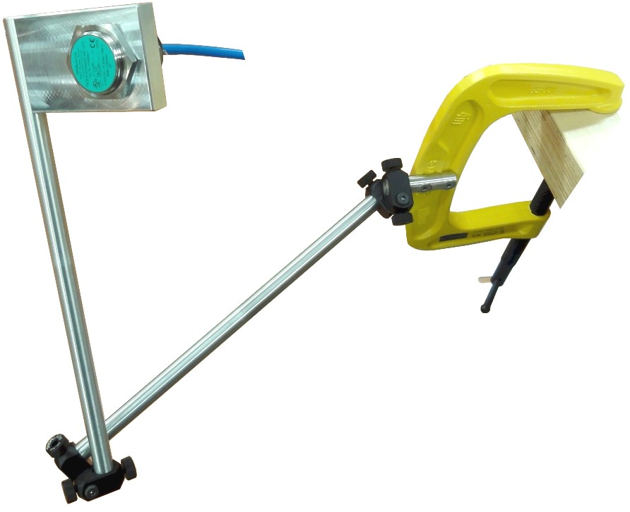
The Magneto® Pump Stroke Sensor is the latest new product from ASD Holdings (Advanced Sensor Design). ASD has successfully introduced unique products for the Oil & Gas Industry for over a decade. In this newest creation we find that the Magneto® Pump Stroke Sensor has been patented by Advanced Sensor Design. It is the world’s first pump stroke sensor that is mounted to the outside housing of the rig pump. It is mounted and stays in place by the use of a heavy duty magnet. The Magneto PSS is completely capable of detecting and counting Oil Rig “mud pump piston strokes” without having to make or be in contact with the pistons.
It is no longer a requirement to open the covers of the Oil Rig mud pumps to install a C-clamp style micro switch with a metal whisker. (Note picture below labeled C-clamp style micro switch) No longer is it necessary to bore a hole through the pump housing in order to get a proximity switch close enough to a piston to count actual strokes. (Note picture below labeled Cable going through pump housing) The Magneto® Pump Stroke Sensor is simple to install and easy to monitor!
The magnetic base of the Magneto® PSS makes it totally different than anything available in the marketplace today relative to its form and fit. However, that is not its only outstanding feature. Advanced Sensor Design is using “State of the Art” electronic circuitry that has the ability to give the end user (Oil Rig Mud Pump Operator) an On/Off switch type electrical output. Just like what the conventional mud pump sensors emit today. The obvious benefit to the oil rig is that No Special accommodations to their Data Acquisition Systems are required.

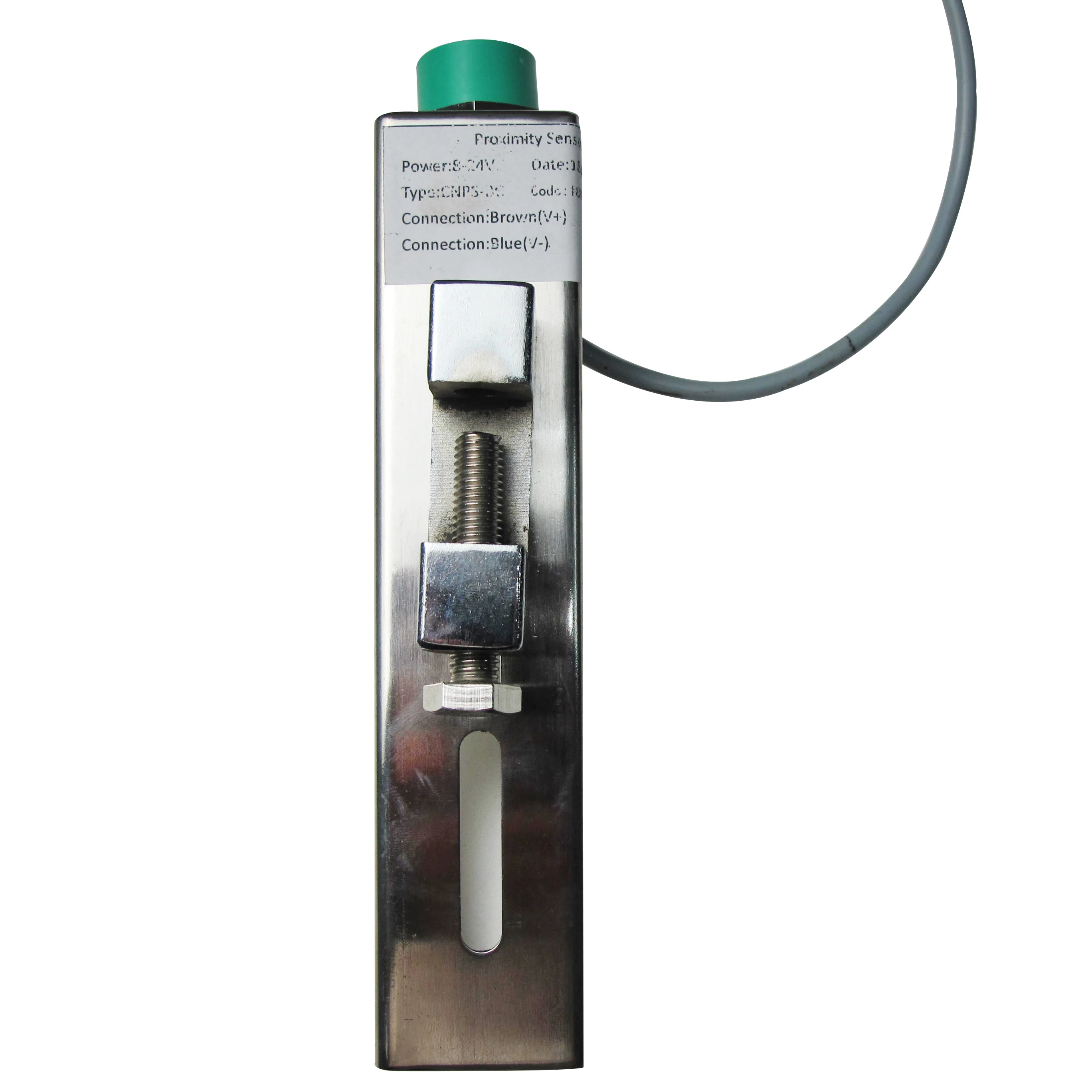
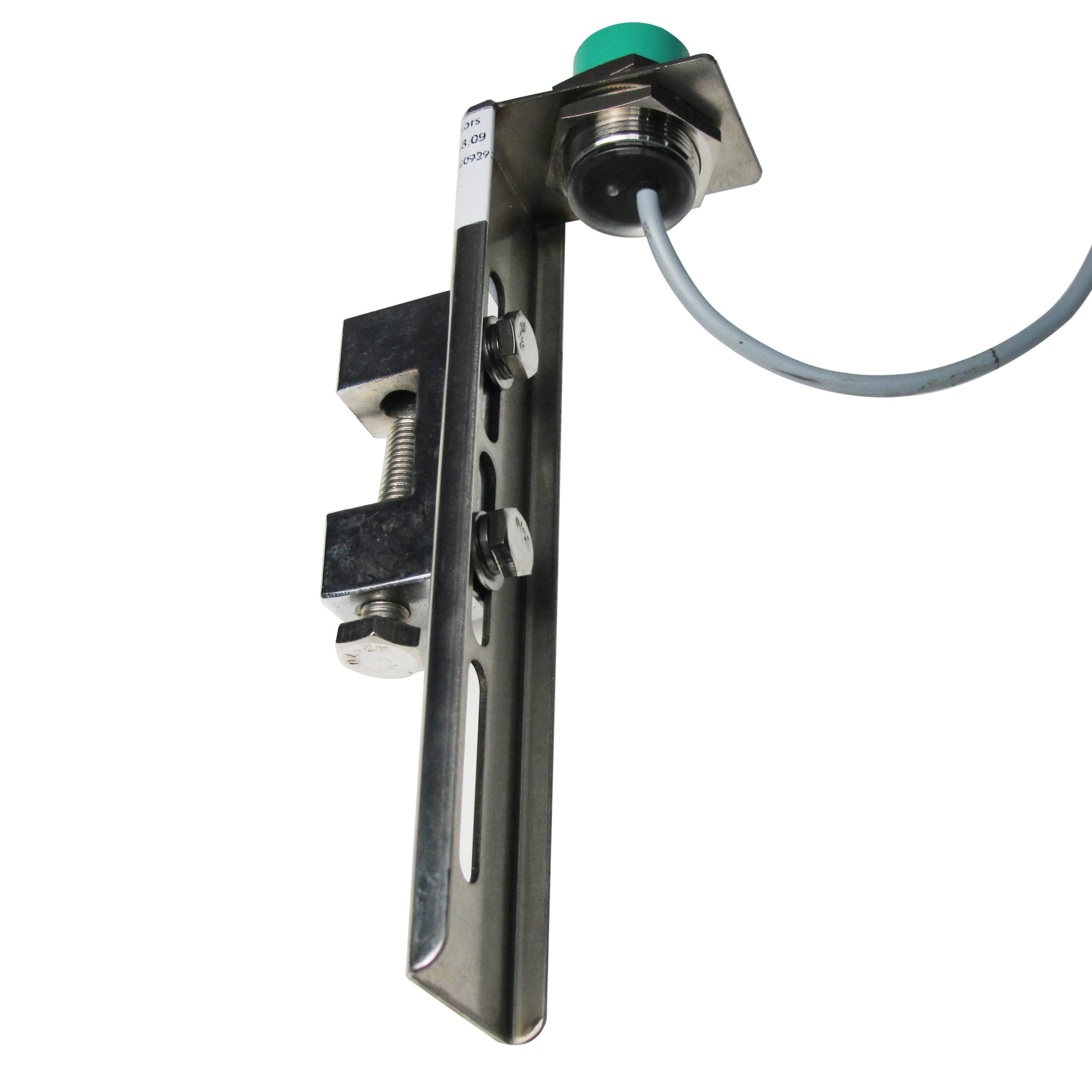
IML-BC11 pump impulse sensor is an inductive proximity switch type sensor, which is used to measure the pump impulse or rotary speed. It has the characteristics of wide voltage range, high precision of repeated positioning, fast frequency response, long service life, vibration resistance, corrosion resistance, water resistance, etc. The bracket adopts galvanizing process, the distance of sensor is easy to adjust, and the direction of change fixation can be adjusted by 90 °.
The pump impact sensor can be fixed in a proper position with a bracket, and the closest distance between the sensing surface of the tested object and the end face of the sensor can be adjusted to be within 15mm (generally 80% of the rated action distance is taken in consideration of the impact of the use environment). Turn on the working voltage, when the sensor is close to the end face of the sensor, the indicator light will be on; when it is far away from the sensor, the indicator light will be off.
1.The pumping sensor can be fixed to the mud pump head by the bracket, or the appropriate part of the turntable, and the closest distance between the position of the sensing surface of the measured object and the end surface of the sensor is within 30 mm. (According to the influence of the use environment, the rated working distance is generally taken. 80%), plus the working voltage, when the end of the inductive sports sensor is close, the indicator light is on; when away from the sensor, the indicator is off.
2.The turntable speed sensor can be fixed to the appropriate part of the drive shaft of the turntable with the bracket. It should be convenient to install and repair. The model of the drill is selected. A piece of iron with a length and width of 30mm is welded on the shaft of the drive shaft or the airbag clutch. The position of the end face should be close to the end face of the sensor. Adjust the fixing nut of the sensor so that the distance between the iron sensor is within the effective range of the working distance.

The Two-pump Digital Stroke Rate Meter monitors and displays the Rate and Total Strokes of up to two individual pumps simultaneously. The unit continually displays, on large easy to read, low power LCD displays, RPM, TOTAL ACCUMULATED STROKES (0-9999 total strokes) and STROKE RATE (8-350 strokes per minute) for each pump. The unit is internally powered by a battery source having an operational life of 3 years.
At Matherne Instrumentation, we"re proud to provide both our two-pump and three-pump stroke counters to companies and oilfield operators across the states of Texas, Louisiana, North Dakota, and Pennsylvania. While our offices are based in Odessa, TX; Lafayette, LA; and Houma, LA, we"re proud to serve those across the cities of Midland, TX; Houston, TX; Williston, ND; and Pittsburgh, PA. To learn more or for a quote, please feel free to give us a call today!
Sales and services for weight indicators, electronic weight indicators, cement recorders, six inch gauges, cylinders, torque assemblies, line pull assemblies, 1502 assemblies, wireline gauges and cylinders, depthometers, electronic depth systems, counters, diaphragms, auto drilling systems, rotary torque systems, and pump stroke counters.

Our pump stroke counter systems (CPS101 Series) measure the stroke rate and number of strokes on mud pumps. The oilfield pump stroke system is user-friendly and reliable and is configurable to measure up to three mud pumps at once. Our digital pump stroke counter systems are manufactured here in the U.S. by Crown Oilfield Instrumentation, and Crown’s Pump Stroke Counter provides easy monitoring of strokes per minute on multiple mud pumps. Each mud pumps’s stroke rate can be selected individually and the display is updated regularly for accurate monitoring. LCD displays indicate both pumps strokes per minute and the total number of strokes. Located at the bottom of the panel, push buttons provide easy operation and reseting of each pump. When you need to accurately monitor and maintain the amount of mud being pumped, you can trust Crown’s oilfield stroke counters.

Poor Boy"s Instrument, Inc."s Digital Pump Stroke Counter System monitors and displays the number of strokes and stroke rate for mud pumps. The system is available in (1) pump, (2) pump or (3) pump configurations. The digital counter uses LCD displays to indicate, both the total number of strokes on each pump and the strokes per minute on each pump. Push buttons located on the front of the head make it easy for the operator to reset each pump count. A stainless steel enclosure ensures reliable service even in the most severe operating environments. Complete system includes Digital stroke counter, head mounted in stainless steel enclosure, cable assemblies with connectors, and stroke counter switch with mounting clamp.
Poor Boy�s Instrument, Inc.�s Proximity Detection System eliminates the need for belt-driven generators on RPM and SPM systems. The system uses reliable and durable proximity sensors which are mounted permanently on the mud pump for the SPM and near the rotary table for the RPM. The signal received from the sensor is processed into an output signal in the form of a pulse signal or analog signal for operation of electric meters, digital pump stroke counters, recorders, etc. Standard configuration can supply signal for (2) SPM functions, and (1) RPM function (other configurations available). The system includes a tough NEMA 4 enclosure which houses the modules and processors, cable assemblies with connectors for (3) functions, and (3) proximity detection sensors. Output cables and meters are optional with system.
To request a quote for one of our Digital Pump Stroke Counter Systems please click here or send an email which includes the options that meet the needs for you installation to sales@poorboysinstrument.com. Please do not send any non-public personal information. Please allow two business days for a response.

The SK-8Y2X series alloy film sensor consists of an ion-beam sputtering alloy film sensor and a signal modulation circuit and is applicable to detection of fluid pressure, differential pressure or liquid level. The Sensor is made using the modern film equipment and etching technique. The sensor has unique technique and excellent performance and can stably run in severe environment. The liquid medium pressure/differential pressure acts on the corrosion resistant stainless steel elastic film to deform the film, as shown in the strain schematic diagram. An alloy film strain resistance comprising Wheatstone bridge has been made on the film. Film deformation changes the geometry and value of the resistance, and the bridge outputs corresponding electrical signals. The electronic circuit amplifies the bridge output signals and converts them into standard 4~20mA current signals for output.
![]()
We usually think and practice corresponding for the change of circumstance, and grow up. We aim at the achievement of a richer mind and body as well as the living for Mud Pump Stroke Counter Sensor, , , , Sincere cooperation with you, altogether will create happy tomorrow!

Acadiana Pump Stroke Counter or Rate Meter Displaying both the total number of strokes and the strokes per minute for two or three mud pumps (up to 1,024 strokes per min per pump), the Acadiana Oilfield Instruments’ pump stroke counter has easy to use push buttons for resetting the pump count. Built-in a stainless steel design, this indicator will last in any environment.
The present invention relates in general to oilfield equipment and in particular to the measurement of a recurring event. A preferred embodiment of the invention relates to equipment for the oil and gas drilling and production industry and particularly to an event sensor for rotary or reciprocal oilfield machinery.
In the art of drilling oil and gas wells, it is well known to count certain reoccuring events, such as the revolutions of the drill pipe, the number of strokes of a mud pump or the like. For example, during oil and gas drilling and production operations it is necessary to monitor various events to provide adequate control and safety. The pump stroke of the drilling mud slush pump is continuously monitored during an oil and gas well drilling operation to monitor the mud being pumped into the well. In the prior art, mechanical contact switching systems have been used to count the pump strokes. These mechanical connections have disadvantages and in order to advance the state of the art of oil and gas drilling and production, it is desirable to improve the systems for transmitting pump stroke information. The prior art systems have encountered the problems of poor access to the reciprocating or rotary element due to its motion and location, and vulnerability of pick-ups due to routine machine maintenance and wear of contacting parts. The present invention will result in fewer service problems due to failure or misalignment and will provide consistent accuracy.
Prior art systems have used limit switches activated by the rotating element or the reciprocating rod. Usually access to this element or rod was at a service entrance where routine mechanical maintenance resulted in physical displacement of the sensor. The present invention can be attached to the machinery element in a position that is more accessible but less likely to be tampered with. An understanding of the uses of such a system in oil well drilling and production operations can be obtained from a review of U.S. Pat. No. 3,614,716; U.S. Pat. No. 3,608,653 and U.S. Pat. No. 3,740,739. These systems disclose various monitoring systems for monitoring potential blowouts and lost circulation in an oil well drilling operation.
In U.S. Pat. No. 3,716,707 to M. J. Sharki et al, patented Feb. 13, 1973 and U.S. Pat. No. 3,929,014 to M. J. Sharki, patented Dec. 30, 1975, pneumatic ratemeters and counters are shown. A sensor valve receives a mechanical force from a pump rod and operates to pressurize an air tank from a regulated air supply.
Pump stroke counting or the determination of other recurring events is determined by providing a force sensor, such as an accelerometer, and a transmitter arranged in a housing adapted to be affixed to a pump piston rod or drive train of the equipment to be monitored. A receiver is positioned at a distance from the force sensor/transmitter and receives the signal from the transmitter. The absence of moving parts or contacts improves the reliability and performance of the present invention. The foregoing and other features and advantages of the present invention will become apparent from a consideration of the following detailed description of the invention when taken in conjunction with the accompanying drawings.
Referring now to the drawings, and in particular to FIG. 1, an embodiment of the present invention is illustrated in conjunction with a slush pump 12 used for pumping drilling mud during an oil well drilling operation. A well bore 13 is shown having the usual casing 18. The well bore 13 contains the rotary drill string 17. The rotary drill string 17 is provided with a bit 14 at its lower end. The drill string 17 is turned by a rotary table 15 mounted in the derrick 16. Drilling mud is pumped from a mud pit 21 through line 23 by pump 12 through a mud delivery line 20 into the drill string 17 and is discharged out of the bit 14 into the well bore 13 and returned from the top of the casing 18 by a mud flowline 22 to the mud pit 21. An openable and closable blowout preventer or rotary drill head 19 of any suitable conventional type is provided at the upper end of the casing 18.
It is necessary to monitor various parameters during the drilling of the well. For example, one of the parameters is the stroke rate of the mud pump that circulates the drilling mud. An example of the need for monitoring this parameter is the danger of blowout in a well. High pressure gas from the underground reservoir pierced by the borehole may enter the borehole and displace mud out of the borehole into the mud pits. The removal of the mud from the borehole decreases the pressure opposite the underground reservoir and allows more gas to enter the borehole. This is a cycle that can lead to a blowout of the well if action is not taken to correct it. By monitoring the volume of mud going into the borehole and the volume of mud returning to the mud pits, it is possible to obtain a warning of an impending blowout. It will therefore be seen that reliable and constant measurement of the pump stroke of the mud pumps is a necessary part of such a monitoring system because this allows an accurate determination of the volume of mud being pumped into the well.
The present invention comprises a force sensor, transmitter, receiver and signal conditioning components. The force sensor and transmitter are in one package. As shown in FIG. 1, the force sensor and transmitter package 10 is mounted in a fixed position on the rotating element 11 of the equipment to be measured. The force sensor and transmitter package 10 is mounted on the bull wheel 11 of the oilfield slush pump 12. This element rotates in a vertical plane. The force sensor measures the force between a weight and the bull wheel in one degree of freedom lying in the plane of the wheel 11. The force sensor and transmitter package 11 comprises a force sensor, such as an accelerometer, and a transmitter arranged in a housing adapted to be affixed to the machine element 11 which rotates in a vertical plane. As the element 11 rotates, the sensor measures gravitational and centrifugal forces, the former providing a sinousoidally varying sensor output having a period equal to the rotational period of the machine element 11. The transmitter is a battery-powered R.F. device which is activated once each revolution by an amplifier-detector A.C.-coupled to the output of the force sensor. A one-shot multivibrator is used to transmit a short burst during the on-time and such burst may be modulated for better noise rejection by the receiver. The receiver 24 is located remotely from the sensor/transmitter package 10 and comprises an R.F., detector, amplifier and, if required, a demodulator. Each output pulse from the receiver circuit represents one rotation of the machine element and division circuits are employed if it is desired to determine events of machine components other than the rotating element and having gear ratios with respect to the rotating element which differ from 1:1. The outputs are typically used for totalization of events and event rate determinations.
The alignment of the sensor/transmitter package 10 in relation to the bull wheel 11 is shown in FIG. 2. As the wheel 11 rotates at a constant angular velocity, the sensor/transmitter 10 will measure two components of force, one due to gravitational forces and one due to centrifugal forces of the wheel 11. The former is sinousoidally varying with a period equal to the rotation period and the latter is a constant force due to the rotation of the wheel. The transmitter is a low power R.F. device 31, switched on once each rotation by an amplifier-detector 29 which is A.C.-coupled to the output of the accelerometer 25. The on period may be brief provided by one-shot control 30, and the transmitted burst may be modulated for better noise rejection by the receiver. Since the transmitter is switched on for a short period compared to the rotating period, it may be operated by batteries 26 or some internal generator, giving it long, useful life and little maintenance.
FIG. 3 is a graph illustrating the output of the force sensor for various positions of the wheel/sensor combination when rotating at a constant angular velocity "ω". The output for a complete cycle of the wheel 11 due to the gravitational vector is represented by the sinousoidal portion of the waveform. The centrifugal force is represented by the constant part of the output, and is proportional to 4πω2 R2.
In order to provide an output representative of the reciprocating action initially desired to be monitored it is necessary to divide the pulses by the gearing ratio between the bull wheel 11 and the pump piston rod. In the system shown in FIG. 1, the event being monitored is the pump stroke of the slush pump 12. The stroke of the pump piston rod will be related to the rotation of the bull wheel 11 by a fixed ratio dependent upon the gearing involved.
The phase-locked frequency multiplier 41 comprises a phase detector 35, low pass filter (L.P.F.) 36, voltage controlled oscillator (V.C.O.) 37 and feedback frequency divider (of one hundred) 40 as illustrated. The output of the multiplier 41 is 100 pulses per bull wheel revolution. Part three of the receiver 24 is a divide by N circuit 38 where N is an integer set into the circuit externally by the N select unit 39. The divide by N circuit, for example, may be a CD 4018 manufactured by RCA or other manufactures" 4018 circuits. The pulse output of the receiver 24 is the pulse output of the divide by N circuit 38 which corresponds directly to each linear reciprocating action. In the slush pump example of FIG. 1, this corresponds to pump stroke, when N is properly set. For oilfield type slush pumps, the gear ratio ranges from about 2.50 to 8.00 and the actual ratio determines N.
The market is evolving to better and smarter sensors, which can gather more detailed data in order to improve safety, efficiency and geological precision of the well. A big issue now, is that companies have difficulty in measuring the exact amount of drilling fluids (mud) going into and out of the well.
Hohner Automation is based in Wrexham and since 1980, has been making optical encoders to automate general machinery but over the years, have specialised in encoders for the oil and gas industry. Their main customer base now is mud logging companies where they manufacture fully certified rig instrumentation and sensors for mud logging.
The aim of this project is to develop an innovative new sensor for counting mud pump strokes and also monitoring position, speed and efficiency of individual strokes.
This project would see a significant increase in R&D activity for the business and if successful, could result in increased sales and new jobs. Hohner Automation already has an existing route to market/client base and potential of successful commercialisation is high. The market is very large with around 2,000 drilling rigs active in the world and each of these, has several mud pumps.

Monitors and displays the total accumulated mud pump strokes and the stroke rate of up to 4 individual mud pumps simultaneously. Constructed to operate in harsh environments and high vibration, conditions encountered in land and offshore drilling.
Monitors and displays the total accumulated mud pump strokes and the stroke rate of up to 4 individual mud pumps simultaneously. Constructed to operate ...
IRIS RMS is an on-board integrated riser instrumentation system for drilling risers. IRIS RMS integrates sensors with finite element software as well as providing measured data used to predict ...
Monitors and displays the total accumulated mud pump strokes and the stroke rate of up to 4 individual mud pumps simultaneously. Constructed to operate ...


 8613371530291