
mud pump stroke sensor factory

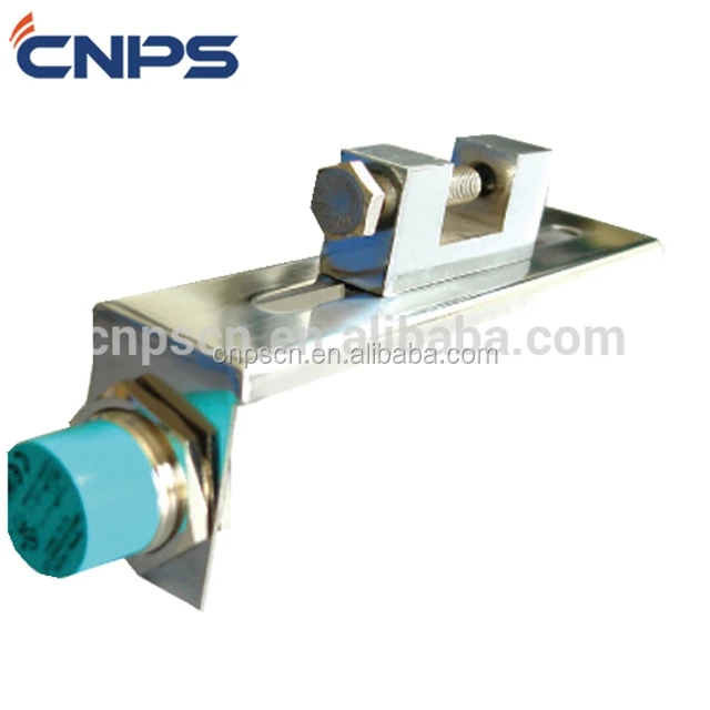
The Magneto® Pump Stroke Sensor is the latest new product from ASD Holdings (Advanced Sensor Design). ASD has successfully introduced unique products for the Oil & Gas Industry for over a decade. In this newest creation we find that the Magneto® Pump Stroke Sensor has been patented by Advanced Sensor Design. It is the world’s first pump stroke sensor that is mounted to the outside housing of the rig pump. It is mounted and stays in place by the use of a heavy duty magnet. The Magneto PSS is completely capable of detecting and counting Oil Rig “mud pump piston strokes” without having to make or be in contact with the pistons.
It is no longer a requirement to open the covers of the Oil Rig mud pumps to install a C-clamp style micro switch with a metal whisker. (Note picture below labeled C-clamp style micro switch) No longer is it necessary to bore a hole through the pump housing in order to get a proximity switch close enough to a piston to count actual strokes. (Note picture below labeled Cable going through pump housing) The Magneto® Pump Stroke Sensor is simple to install and easy to monitor!
The magnetic base of the Magneto® PSS makes it totally different than anything available in the marketplace today relative to its form and fit. However, that is not its only outstanding feature. Advanced Sensor Design is using “State of the Art” electronic circuitry that has the ability to give the end user (Oil Rig Mud Pump Operator) an On/Off switch type electrical output. Just like what the conventional mud pump sensors emit today. The obvious benefit to the oil rig is that No Special accommodations to their Data Acquisition Systems are required.

1.The pumping sensor can be fixed to the mud pump head by the bracket, or the appropriate part of the turntable, and the closest distance between the position of the sensing surface of the measured object and the end surface of the sensor is within 30 mm. (According to the influence of the use environment, the rated working distance is generally taken. 80%), plus the working voltage, when the end of the inductive sports sensor is close, the indicator light is on; when away from the sensor, the indicator is off.
2.The turntable speed sensor can be fixed to the appropriate part of the drive shaft of the turntable with the bracket. It should be convenient to install and repair. The model of the drill is selected. A piece of iron with a length and width of 30mm is welded on the shaft of the drive shaft or the airbag clutch. The position of the end face should be close to the end face of the sensor. Adjust the fixing nut of the sensor so that the distance between the iron sensor is within the effective range of the working distance.

We know that we only thrive if we will guarantee our combined cost competiveness and high-quality advantageous at the same time for Mud Pump Stroke Counter Sensor, , , , Now we have experienced manufacturing facilities with extra than 100 employees. So we could guarantee short lead time and high quality assurance.

Our pump stroke counter systems (CPS101 Series) measure the stroke rate and number of strokes on mud pumps. The oilfield pump stroke system is user-friendly and reliable and is configurable to measure up to three mud pumps at once. Our digital pump stroke counter systems are manufactured here in the U.S. by Crown Oilfield Instrumentation, and Crown’s Pump Stroke Counter provides easy monitoring of strokes per minute on multiple mud pumps. Each mud pumps’s stroke rate can be selected individually and the display is updated regularly for accurate monitoring. LCD displays indicate both pumps strokes per minute and the total number of strokes. Located at the bottom of the panel, push buttons provide easy operation and reseting of each pump. When you need to accurately monitor and maintain the amount of mud being pumped, you can trust Crown’s oilfield stroke counters.

Acadiana Pump Stroke Counter or Rate Meter Displaying both the total number of strokes and the strokes per minute for two or three mud pumps (up to 1,024 strokes per min per pump), the Acadiana Oilfield Instruments’ pump stroke counter has easy to use push buttons for resetting the pump count. Built-in a stainless steel design, this indicator will last in any environment.
Monitors and displays the total accumulated mud pump strokes and the stroke rate of up to 4 individual mud pumps simultaneously. Constructed to operate in harsh environments and high vibration, conditions encountered in land and offshore drilling.
Monitors and displays the total accumulated mud pump strokes and the stroke rate of up to 4 individual mud pumps simultaneously. Constructed to operate ...
IRIS RMS is an on-board integrated riser instrumentation system for drilling risers. IRIS RMS integrates sensors with finite element software as well as providing measured data used to predict ...
Monitors and displays the total accumulated mud pump strokes and the stroke rate of up to 4 individual mud pumps simultaneously. Constructed to operate ...

Today many tools have been developed that make the task of operating the rig more automated and centralized, especially on the newer automated rigs with fully integrated control systems, where a significant set of the tools are integrated. But on traditional rigs these varied systems, developed by disparate companies, have created a complex operation area, jumbled with output displays and controls. Among other things, the systems and methods of the present disclosure helps this complexity issue by reducing the total number of individual systems, sensors, controls and display installations, by rationalizing, integrating systems and hence simplifying the operational areas and system installations for a traditional rig.
Space in the doghouse is at a premium. The knowledge box made sense when the driller was tasked with keeping the IADC report current and clean, and when the freestanding mechanical drilling recorder was positioned nearby. A driller is now required to complete his reports on a computer and utilize an electronic drilling recorder, so the reporting functions and mechanical drilling recorder are now replaced by data acquisition and computer systems. Other equipment is becoming computerized, such as the pneumatic autodriller and directional steering controls, and with each new system a new set of sensors, controls is added to the rig equipment and another interface is added to the doghouse and drillers station
It would be a valuable addition to the field of art to provide a method of augmenting a traditional rig with automated systems. In order to simplify the retrofitting process, and to take advantage of automated technology, among other advantages, it would be valuable to the field of art to provide a system that may flexibly and dynamically provide such advantages as to integrate multiple automated systems, reduce sensor duplication, reduce the number of controls and control boxes, reduce the number of displays, reduce the space required over discrete automated system installations, reduce time to rig up and rig down, improve overall reliability, improve efficiency, provide more capability for less investment, reduce the controls and interface complexity, and improve standardization of interfaces for the end user. BRIEF DESCRIPTION OF THE DRAWINGS
The mud system assembly 112 is shown to have mud pits and mud pumps, and further extends onto the derrick 102 in order to supply the mud into the drill string 106. Mud pumps push the mud all the way through the drill string 106 to the drill bit 110, where the mud lubricates the bit and flushes cuttings away. As more mud is pushed through the drill string 106, the mud fills the annulus around the drill string 106, inside the drill hole 108, and is pushed to the surface. At the surface the mud system assembly 112 recovers the mud and separates out the cuttings. The condition of the mud is assessed and additives are replenished as needed to achieve the necessary mud characteristics. Also at the surface a rig has a blow out prevention system to close in the well bore and protect the well site in the event of a kick as well, and a choke manifold and control system to manage pressurized well bore fluid returns and discharges.
On traditional rig 10, the systems described above are controlled through experience and human perceptions. In this disclosure, a workover rig will in most cases be included in the term traditional rig. Automated systems are available to substantially augment the skill of the operators for many of the systems on the rig 10. Sensors and monitors required for the operation of each automated system may be added to the drill string 106, drill bit 110, mud system assembly 112, pipe handler assembly 114, drawworks, rotary table 118, top drive assembly 116, automated tubular racking system 120, casing running system, floor wrench assembly 118, blow out preventors and choke manifold systems and any other drilling equipment/system on site and in use, with the data collected by the sensors and monitors directed to the doghouse 102 for the driller to review. The separate systems generate a substantial volume of data.
The present device and system offers the driller a unitary, integrated system that has an integrated control center that fits in a convenient space within the dog house. Additional displays and interfaces may be provisioned around the rig site as necessary. Typically the convenient space within the dog house is the knowledge box. In the present system, redundant sensors and monitors are eliminated, the automated controllers are consolidated into a single computer system, and outputs are standardized, for either or both transmission locally and remotely from the rig 10. Automated controllers may include such devices as programmable logic controllers (“PLCs”), programmable automation controllers, personal computers and micro controllers. The present device offers integrated assessment, documentation and control of the systems listed above as examples, as well as other systems involved in the operation of an automated drilling rig 10.
Referring now to FIG. 2, the exemplary automated knowledge box, or “K-Box,” automation system 20 is comprised of an integrated control engine 200 that is operably coupled to elements, including an integrated sensor engine 202, an integrated equipment engine 204, and an integrated report engine 206. Junction boxes may be employed to facilitate coupling intermediate the control engine 200 and a particular element or grouping of elements. The control engine 200 manages and coordinates the interaction of the components encompassing the automation system 20. The control engine 200 is integrated because it may contain the automated controller function for all the devices within the automation system 20, and has the capacity to incorporate more operational systems.
The sensor engine 202 may include devices such as sensors, meters, and detectors, which can detect activity, conditions and circumstances in an area to which the device has access. Components of the sensor engine 202 are deployed at any and all operational areas where information on the conditions in that area may be desired by an operator. Areas for deployment of components include at or near the drill bit 110, the drill string 106, the mud system assembly 112, the pipe handler assembly 114, the top drive assembly 116, and the floor wrench assembly 118, for examples, to detect physical properties that are used by systems to assess the drilling operations. Any other operational system that may be added to the automated system 20 may require unique sensor engine 202 components that may need to be place in positions essential to that particular added system. Readings from the sensor engine 202 is fed back to the control engine 200. The control engine 200 may send signals to the sensor engine 202 to adjust the calibration or operational parameters. The sensor engine 202 is integrated because it contains sensing function for all the systems within the automation system 20, and has the capacity to incorporate more operational systems.
The operational equipment engine 204 may include devices that function to facilitate the drilling operation. The equipment engine 204 may include hydraulic rams, rotary drives, valves, and pumps, just to name a few examples. The equipment engine 204 may be designed to exchange communication with control engine 200, so as to not only receive instructions, but to provide information on the operation of equipment engine 204 apart from any associated sensor engine 202. The equipment engine 204 is integrated because it contains operational equipment functions for all the systems within the automation system 20, and had the capacity to incorporate more operational systems.
Centralizing the coordination of data with the integrated automation system 20 may reduce redundancy of various components of individual systems, including automated controller"s and operational sensors, as well simplifying and organizing operational interfaces, while at the same time locating the automated systems in the same place from where the manual operations were coordinated. The integrated automation system 20 may be installed in a traditional rig that does not currently have automated systems. The integrated automation system 20 may also be installed in a traditional rig has an automated system. In the latter situation the current disclosure may be used to integrate the existing system with additional systems, or may replace some or all of the existing components with different components to accomplish the same systemic objectives.
Referring now to FIG. 3, the exemplary automation system 20 is comprised of a variety of operational, monitoring and reporting systems. A typical exemplary operational system may comprise a user interface, operational equipment, sensors, actuators, and control software, as needed for a particular system, which are incorporated in the respective engines shown in FIG. 2. In this way the operational system may be elementally embodied in two or more of the integrated control engine 200, the integrated sensor engine 202, the integrated equipment engine 204, and the integrated report engine 206. Systems may be dynamically selected to be active at any moment in an automation system 20, and when active may share the operably coupled resource components. Dynamic selection allows the automation system 20 to possess the potential to comprise a wide assortment of operating systems, while at the same time permitting convenient management of the actual operating functionality of the automation system 20. Exemplary resource components may include a common user interface 22, processor 24 and memory 26, of control engine 200, as well as the sensor engine 202, the equipment engine 204, and the report engine 206, as appropriate.
The exemplary automation system 20 includes an equipment condition system 302, a directional steering system 304, an electronic choke system 306, a drilling pressure system 308, a mud pump control system 310, a kill sheet system 312, a daily reporting system 314, a safety analysis and report system 316, a traveling equipment position system 318, a top drive position system 320, a pipe handler system 322, a floor wrench system 324, a remote access system 326, an autodriller system 328, a rig drilling data system 330, a pit volume totalizer system 332, a mud gas system 334, a mud flow system 336, a mud density system 338, a rig video system 340, automated tubular racking system 342, a casing running system 344, a BOP (“blowout preventer”) control system 346, a pipe centralizing arm system 348, a drawworks system 350, a coiled tubing unit system 352, a slips system 354, and a measurement-while-drilling (“MWD”) system 356. Many of these systems are available from multiple suppliers. Though the current system provides for integrating the varied systems, it may still be more desirable to obtain as many systems as possible from the same manufacture. Nabors Industries Ltd. may provide a number of the various systems through their affiliated companies.
The exemplary drilling pressure system 308 includes components of a pressure control system that maintains constant bottomhole pressure (“BHP”) while drilling. Drilling operations in challenging environments can benefit from being able to overcome the pressure limitations of conventional drilling and expand prospective drillable areas. Constant bottomhole pressure is achieved through rapid, dynamic and consistent backpressure control without interruption, with or without rig pumps. A potentially acceptable system that may be modified and incorporated into the drilling pressure system 308 includes the Dynamic Annular Pressure Control (“DAPC”) System, available from At Balance Americas L.L.C. The DAPC System can achieve constant BHP using a control system integrated with real-time hydraulics modeling, and an auxiliary pump to provide backpressure when the rig pumps are off.
The exemplary mud pump control system 310 includes components of a mud supply and circulation system that may be modified and incorporated into the mud pump control system 310. Mud pumps are typically large, high-pressure reciprocating pumps used to circulate the mud on a drilling rig 10. A typical mud pump is a two or three-cylinder piston pump with replaceable pistons that travel in replaceable liners, and are driven by a crankshaft actuated by an engine or a motor. Mud pumps keep the critical supply of mud moving to the bottom of the drill string 106 and back up the drill hole 108 to the surface for reclamation. The flow of mud must be maintained at an appropriate level as dictated by the situation being experienced. A control system switches the pumps on and off, and adjusts the pumps speed of operations, in order to adjust the rate of mud flow. A potentially acceptable system that may be modified and incorporated into the mud pump control system 310 includes an electric motor control system provided by National Oilwell Varco, of Houston, Tex.
The exemplary pit volume totalizer system 332 includes components of an integrated system for the management of mud volumes throughout the mud system. Such systems take into consideration intermittent power and the potential for a critical situation to arise quickly, and manage the positioning of mud to be able to address unfavorable situations. A potentially acceptable system that may be modified and incorporated into the pit volume totalizer system 332 includes the Pason Pit-Bull™ Pit Volume Totalizer & Flow Show, available from Pason Systems Corporation.
The exemplary mud gas system 334 includes components of a system to detect changes in relative volumes of hydrocarbon gases at the surface without complex offline analysis, delicate instrumentation, or expensive gas chromatographs. The system may send data via remote access system 326 to relevant observers wherever they may be located. Alarms can be set to notify the geologist if the gas level in the mud reaches or falls below a desired percent setting. A potentially acceptable system that may be modified and incorporated into the mud gas system 334 includes the Pason Total Gas System, available from Pason Systems Corporation.
The exemplary mud flow system 336 includes components of a system to monitor mud flow rate and velocity sensor, which has proven to be effective for early gas kick detection through recognizing changes in the flow rate. Early detection permits rig personnel extra time to mitigate an upcoming gas bubble. A potentially acceptable system that may be modified and incorporated into the mud flow system 336 includes the Rolling Float Meter, available from Epoch Well Services, Inc.
The exemplary mud density system 338 includes components of a system to monitor and maintain the density of the drilling mud. Automated sensors and the digital electronics are immersed in the mud pit in order to maintain continual monitoring. A potentially acceptable system that may be modified and incorporated into the mud density system 338 includes the Mud Density Sensor, available from Epoch Well Services, Inc.
The exemplary BOP control system 346 includes components of a blowout preventer system at the top of a well permits the drill hole 108 to be closed if the drilling crew loses control of formation fluids. By closing the BOP, the drilling crew may regain control of the reservoir, typically by increasing the mud density until it is possible to open the BOP and retain pressure control of the formation. A potentially acceptable system that may be modified and incorporated into the BOP control system 346 includes the U-BOP™ blowout preventer, by Cameron International Corporation, of Houston, Tex.
The manual equipment engine controls 414 may be considered operational systems controls, since they permit the user of the automation system 200 to affirmatively affect the operation of particular pieces of the equipment engine 204 (shown in FIG. 2). The exemplary manual equipment engine controls 414 include a power button, a stop button, a start button, an emergency stop button, an alarm indicator, autodriller controls for ROP, WOB and delta pressure, an on/off switch for the audible alarm, an on/off switch for the directional steering control system, a crown/floor saver on light, a mud pump stop button, choke opening and closing switches, and buttons to modify the image on the video displays 412. Additional manual equipment engine controls 414, may be remotely located from the cabinet 404, and positioned at various locations around the rig 10 to meet a user interface requirement in a specific location.
In an exemplary embodiment, the operational system control circuitry 416 facilitates the communication of control engine 200 with the integrated sensor engine 202, the integrated equipment engine 204, and the integrated report engine 206 through electrical wiring, either wired directly or through any of a variety of bus configurations. The electronic signals may activate horn, lights for alarms, the recording of information in memory to act as a chart recorder. The electronic signals may travel through the user interface 22 to other computer systems, where additional processing and archival operations may occur. In an exemplary embodiment, the control engine 200 sends controlling outputs from its processor 24 to external devices and equipment for control purposes via electronic signals that may operate within the configurations of 4-20 mA, 0-24 V DC and 0-10 V DC.
Referring to FIG. 4B, the exemplary set of manual equipment engine controls 414 includes autodriller controls 418 for an autodriller system 328, a console alarm control 420, a directional steering control system control 422 for a directional steering system 304, choke controls 424 for an electronic choke system 306, a crown/floor saver control 426, a mudpump control 428 for a mud pump control system 310, a keyboard control 430, and power controls 432.
In the exemplary embodiment, autodriller controls 418 include a ROP control knob, a WOB control knob, delta pressure control knob, an E-Stop button, a start button, a stop button, and an alarm ack button. The ROP control knob, which is similar to a potentiometer, allows for setting of the ROP set point or target, and the ROP limit or shutdown. The WOB control knob, which is similar to a potentiometer, allows for setting of the WOB set point or target, and the WOB limit or shutdown. A delta pressure control knob, which is similar to a potentiometer, allows for setting of a differential pressure set point or target, a differential pressure limit or shutdown, and a mud pump high pressure alarm point. An E-Stop or emergency stop mushroom maintained pushbutton to stop automatic driller. A start illuminated momentary pushbutton to start automatic driller and provide indication when running. A stop momentary pushbutton to stop the automatic driller. An Alarm Ack or alarm acknowledgement illuminated momentary pushbutton to provide visual indication of autodriller alarms, and a method for acknowledgement and horn silencing.
In the exemplary embodiment, choke controls 424 include two Open/Close spring return-to-center three-position selectors used to open and close chokes 1 and 2, respectively, and a display momentary pushbutton used to immediately select the choke display on video display 412. In the exemplary embodiment, crown/floor saver control 426 include a Saver On indicator that provides visual indication that the crown/floor saver is active. In the exemplary embodiment, mudpump control 428 includes a Stop mushroom maintained pushbutton to stop the mud pumps. In the exemplary embodiment, keyboard control 430 includes a Left/Right maintained two-position switch that allows one keyboard to be used with two displays as video display 412.
Referring to FIG. 5, an exemplary method 50 for incorporating automated systems into a drilling rig 10 comprises removing an existing driller"s desk, if such a desk exists, at 502, installing an integrated control engine system at 504, installing communication link capacity for the components of the automation system at 506, installing a sensor engine at 508, installing an equipment engine at 510, and dynamically activating selected engines at 512. The optional preliminary step of removing an existing driller"s desk at 502, depicted with dotted lines, may be necessary before installing the integrated control engine system at 504. The control engine 200 is an example of an integrated control engine system that can be installed at 504. The exemplary control engine 200 may be designed to fit into the same space as the traditional knowledge box, such as in the form of a K-Box device 40. The traditional knowledge box can be cut from the doghouse 104 and the control engine 200, which may be in the form of the K-box device 40, may be welded in its place in a short period of time.
The communication links installed at 506 permits the coupled elements and engines to transfer and exchange data, and may include conventional wiring, and may incorporate wireless communication methods, such as infrared, Wi-Fi® and BlueTooth®, which are provided merely as examples. The link capacity established at 506 may connect the control engine 200 with any element of the sensor engine 202, the operational equipment engine 204, and the report engine 206. Additionally, the link capacity established at 506 may be installed in anticipation of future elements, so that, for example, a particular sensor may not be available, but the communication is put in place in anticipation of the sensor.
The sensors and equipment controls installed at 508 include the various sensors and meters to provide necessary input to the control engine 200, as well as hydraulic rams, valves, pumps and other pieces of equipment that are operable by the automated systems 20.
In the exemplary embodiment, the display area 606 includes information regarding drilling operations and the rig drilling system 330, including the ROP, gas units, hook load, WOB, pump pressure, RPM"s, total pit volume, and total pump operation time. A rig drilling data system 330 may obtain information to display in display are 606 from a variety of sources, including a hookload sensor, a pump pressure sensor, a pump stroke sensor, a casing pressure sensor, a return flow sensor, a block position or ROP sensor, a pit levels sensor, a bit torque sensor, a bit RPM sensor, a top drive elevator position sensor, a MWD sensor, and an alarm system. The sensors within rig drilling system 330 may provide analog or digital signals to the automation system 200, wherein the processor 24 uses the information to render a representative image of what the data means through the user interface 22, which in this example is the display screen 600. The connection between the sensors and the automation system 200 may be made with dedicated connections or may be connected through any of a variety of shared bus configurations. An exemplary embodiment may display other information than that shown, pertaining to the rig drilling system 330.
In the exemplary embodiment, the system display area 608 includes information regarding the electronic choke system 306, and includes operational buttons to open or close the choke, as well as a button to render information regarding choke position on the video display 412. A choke control system 306 may obtain information to display in display area 608 from a variety of sources, including a pump pressure sensor, a pump stroke sensor, a casing pressure sensor, a return flow sensor, a pit levels sensor, and an alarm system. The sensors within electronic choke system 306 may provide analog or digital signals to the automation system 200, wherein the processor 24 uses the information to render a representative image of what the data means through the user interface 22, which in this example is the display screen 600. The connection between the sensors and the automation system 200 may be made with dedicated connections or may be connected through any of a variety of shared bus configurations. An exemplary embodiment may display other information obtainable than that shown pertaining to the electronic choke system 306.
In the exemplary embodiment, the paired analog and digital displays area 610 includes information regarding the drilling pressure system 308, and includes the pump pressure, the casing pressure, the strokes per minute total, and the block position. A managed pressure drilling system 308 may obtain information to display in display area 610 from a variety of sources, including a hookload sensor, a pump pressure sensor, a pump stroke sensor, a casing pressure sensor, a return flow sensor, a block position or ROP sensor, and an alarm system. The sensors within drilling pressure system 308 may provide analog or digital signals to the automation system 200, wherein the processor 24 uses the information to render a representative image of what the data means through the user interface 22, which in this example is the display screen 600. The connection between the sensors and the automation system 200 may be made with dedicated connections or may be connected through any of a variety of shared bus configurations. An exemplary embodiment may display other information than that shown pertaining to the drilling pressure system 308.
In the exemplary embodiment, the historical data display area 612 includes additional information regarding the drilling pressure system 308, and includes a historical graph that is developed in realtime of the pump pressure, the casing pressure, the strokes per minute total, and the fullup volume. The sensors within drilling pressure system 308 may provide analog or digital signals to the automation system 200, wherein the processor 24 uses the information to render a representative image of what the data means through the user interface 22, which in this example is the display screen 600. An exemplary embodiment may display other historical information pertaining to the drilling pressure system 308 that the processor 24 can render from the information obtained by various sensors.
In an exemplary embodiment, the system display area 614 includes information regarding the drilling operations and the rig drilling data system 330, including total strokes, fill up volume, gain/loss and circulating hours. An exemplary embodiment may display other information pertaining to the rig drilling data system 330.
The present device permits a substantial reduction in redundancy created by the prior approach of installing individual, disparate systems. A prior art auto driller system 328 may have a hookload sensor, a pump pressure sensor, a pump stroke sensor, a casing pressure sensor, a block position or ROP sensor, a bit torque sensor, a bit RPM sensor, a top drive elevator position sensor, a MWD sensor, an alarm system, a visual display, and a set of operational controls. A prior rig drilling data system 330 may have a hookload sensor, a pump pressure sensor, a pump stroke sensor, a casing pressure sensor, a return flow sensor, a block position or ROP sensor, a pit levels sensor, a bit torque sensor, a bit RPM sensor, a top drive elevator position sensor, a MWD sensor, an alarm system, and four visual displays. A prior mud logging system may have a hookload sensor, a pump pressure sensor, a pump stroke sensor, a casing pressure sensor, a return flow sensor, a block position or ROP sensor, a pit levels sensor, a MWD sensor, an alarm system, and two visual displays. A prior MWD system 356 may have a pump pressure sensor, a return flow sensor, a block position or ROP sensor, a MWD sensor, an alarm system, and two visual displays. A prior directional drilling system may have a hookload sensor, a pump pressure sensor, a pump stroke sensor, a casing pressure sensor, a return flow sensor, a block position or ROP sensor, a bit torque sensor, a bit RPM sensor, a MWD sensor, an alarm system, and a visual display. A prior directional steering control system 304 may have a bit torque sensor, a bit RPM sensor, a MWD sensor, an alarm system, a visual display, and a set of operational controls. A prior top drive position system 320 may have a block position or ROP sensor, a bit torque sensor, a bit RPM sensor, a top drive elevator position sensor, an alarm system, a visual display, and a set of operational controls. A prior equipment condition monitoring (“ECM”) system 302 may have a hookload sensor, a pump pressure sensor, a pump stroke sensor, a casing pressure sensor, a return flow sensor, a block position or ROP sensor, a pit levels sensor, a bit torque sensor, a bit RPM sensor, a top drive elevator position sensor, a MWD sensor, an alarm system, and a visual display. A prior mud pump synchronizer (“MP Sync”) may have pump stroke sensor, an alarm system, a visual display, and a set of operational controls. A prior soft torque system may have a hookload sensor, a bit torque sensor, a bit RPM sensor, an alarm system, a visual display, and a set of operational controls. A prior crown floor saver system may have a block position or ROP sensor, a top drive elevator position sensor, an alarm system, a visual display, and a set of operational controls. A prior choke control system 306 may have a pump pressure sensor, a pump stroke sensor, a casing pressure sensor, a return flow sensor, a pit levels sensor, an alarm system, a visual display, and a set of operational controls. A prior managed pressure drilling system 308 may have a hookload sensor, a pump pressure sensor, a pump stroke sensor, a casing pressure sensor, a return flow sensor, a block position or ROP sensor, an alarm system, two visual displays, and a set of operational controls. If all of these systems were to be combined in a single automation system 20, according to the current disclosure, the exemplary automation system 20 could result in a reduction of five hookload sensors, six pump pressure sensors, seven pump stroke sensors, five casing pressure sensors, five return flow sensors, seven block position or ROP sensors, three pit levels sensors, six bit torque sensors, six bit RPM sensors, four top drive elevator position sensors, six MWD sensors, twelve alarm systems, seventeen visual displays, and seven sets of operational controls.

Centerline Manufacturing is committed to the highest level of customer service quality. Every Centerline pump is comprehensively and repeatedly tested at diverse pressure levels to assure that it goes to our customer in perfect operational order. Centerline technicians work to ensure that our customers fully understand the operation of the model being delivered. If a customer"s pump is down, we understand the importance of timely response and parts availability. Centerline technicians will assess the problem and make repairs to bring the pump back into new specification. The Centerline mud pump technicians are well versed and qualified to operate and repair any product that is provided to the customer.

n108_BITDI n11_MWD Pressure Loss Mud Plastic
LCD AZI Field Strength Buoyancy Mud Pump 1
n19_BDIPC measured and n24_MWD n18_LBDI Local Magnetic Mud Motor Diameter of Liner –
ALCD calculated Magnetic MD P Dip Angle Torque Mud Pump 2
n22_GZCAL n21_GZCA n46_LSTROKE Length of Stroke –
CD LC 2 Mud Pump 2
n96_HKL_C Mud Weight – n31_SIGM Min. Horizontal Calculated BHA Inner
n111_ROPC Difference between Mud Weight – n32_SIGM Vertical Frictional Casing Inner
Real-Time Data (Blue) Mass Flow n101_MMRP Mud Motor BHA Outer

Deploying an embedded system with that could be retrofitted onto existing pumps, to monitor and analyze mud pump vibrations. helped reduce human exposure to hazardous environments.
As an integral part of onshore and offshore drilling, mud pumps circulate drilling fluids to facilitate drilling oil and natural gas wells. Mud pumps stabilize pressure and support the well during the drilling process and drilling fluids provide friction reduction and a means to remove cuttings. We created a leak detection system for hex pumps. The hex mud pump (see Figure 1) has six pistons, six suction valves, and six discharge valves. The six pistons are driven by a rotating, asymmetric cam. We designed a patented leakage system based on CompactRIO in house. The system monitors the suction and discharge valves using accelerometers.
The Case for an Automated Monitoring SystemValve leaks in piston pumps are often discovered at a late stage when the leaks are so severe that they induce large discharge pressure fluctuations and create washout damages. When a severe leak is detected, we localize it manually by listening to the fluid modules while the pump is running, but it is difficult to uniquely localize the leak and distinguish between a suction valve leak and a discharge valve leak.
Human exposure to hazards is the main disadvantage of manual detection, verification, and localization. Mud pumps convert large amounts of power and often output high pressures up to 350 Bar discharge. Additional equipment in pump rooms also generates high acoustic noise pressure levels that can exceed 100 dBA and cause health and hearing damage if humans are not correctly protected (see Figure 2).
Discovering the Vibration MethodDuring a vibration monitoring project for hex pumps, we discovered the possibility of detecting leaks using accelerometers. We recorded vibrations at different locations, both on the pump and on the discharge line, along with suction pressure, discharge pressure, and pump speeds for different pump conditions. We used a 20 kHz sampling frequency and recorded 5-second snapshots with intervals of a few minutes. On one occasion, the vibration signature significantly changed during a 15 minute period. We soon realized the spot was a growing valve leak.
After the initial discovery, we performed more tests to further explore the leak detection possibility. Figure 3 shows vibrations of all six valve blocks when discharge valve 2 (D2 valve) has a severe leak. The trace numbers indicate the accelerometer/valve block number. The high intervals of the dashed help curves represent the theoretical suction phases that happen when the suction valves are closed. These curves offer easy interpretation of the vibration signals and are derived from the proximity of the sensor signal (not shown). The low values of the help curves represent the theoretical closing of the discharge valves, which happens when the respective pistons retract. The leak intervals have a lag time shift relative to the theoretical intervals. This time shift is on the order of 25 ms and comes from 1) valve inertia causing delayed valve closing, and 2) fluid compressibility causing a finite piston stroke to compress and decompress the fluid.
Leak Detection SystemBased on that encouraging experience, we wanted to include this condition-based maintenance system as a standard feature on all hex pumps. We developed the system as a stand-alone module to add to the existing hex pump control system (see Figure 4). Slightly simplified, it consists of the following components: accelerometers (one per valve block), a proximity sensor picking up pump speed and phase, a discharge pressure sensor, an embedded monitoring system (CompactRIO with NI 9234 acquisition modules for powering the accelerometers and acquiring high frequency data), signal processing software and alarm logics implemented using LabVIEW software running on the CompactRIO monitoring system, and an HMI user interface developed in LabVIEW.
The default sampling frequency of the signals is 25 kHz, but the system can handle higher rates if necessary. The bandpass filter is optional, but experience shows that it improves contrast and detection sensitivity. Signal strength normalization by the median vibration level makes the detection nearly independent of the inherent ambient vibrations, which increase rapidly with increasing pump speed and discharge pressure. The last requirement, that the detected leaks last for a set time, eliminates erratic alarms caused by debris or large particles that can cause temporary seal malfunction.
Figure 5 shows a 1.5 second snapshot of the vibration signatures after a severe leak developed in the D3 valve. It shows the filtered vibration signals from all six accelerometers during a 1.5 second snapshot. Acceleration signal 3 has enhanced noise amplitude during the D3 phase. A closer look at the other signals reveals that the leak induced vibrations are transferred to the other accelerometers during the same time intervals. However, the vibration transfer is relatively low, actually less that -20 dB for neighboring valve blocks and even less for the other blocks, so vibration transfer is not a serious problem in hex pumps.
CompactRIO and LabVIEW proved to be fast tools for prototyping our system and gave us an embedded deployment system that we can reliably retrofit to existing pumps. In comparison to other leak detection methods, which are based on analyzing discharge pressure, we found our vibration-based methods to be more robust and reliable, especially when it comes to localizing a leak. Our studies show that an alternative method can be applied for shaft-driven piston pumps having either an integrated valve block or split blocks with a high vibration transfer. Leak localization for this kind of pump is mainly based on the phase of the pulsating vibration level. We can use it to localize one dominating leaky valve at a time.
Monitors and displays the total accumulated mud pump strokes and the stroke rate of up to 4 individual mud pumps simultaneously. Constructed to operate in harsh environments and high vibration, conditions encountered in land and offshore drilling.
Monitors and displays the total accumulated mud pump strokes and the stroke rate of up to 4 individual mud pumps simultaneously. Constructed to operate ...
IRIS RMS is an on-board integrated riser instrumentation system for drilling risers. IRIS RMS integrates sensors with finite element software as well as providing measured data used to predict ...
Monitors and displays the total accumulated mud pump strokes and the stroke rate of up to 4 individual mud pumps simultaneously. Constructed to operate ...


 8613371530291