
mud pump stroke sensor in stock

Our pump stroke counter systems (CPS101 Series) measure the stroke rate and number of strokes on mud pumps. The oilfield pump stroke system is user-friendly and reliable and is configurable to measure up to three mud pumps at once. Our digital pump stroke counter systems are manufactured here in the U.S. by Crown Oilfield Instrumentation, and Crown’s Pump Stroke Counter provides easy monitoring of strokes per minute on multiple mud pumps. Each mud pumps’s stroke rate can be selected individually and the display is updated regularly for accurate monitoring. LCD displays indicate both pumps strokes per minute and the total number of strokes. Located at the bottom of the panel, push buttons provide easy operation and reseting of each pump. When you need to accurately monitor and maintain the amount of mud being pumped, you can trust Crown’s oilfield stroke counters.

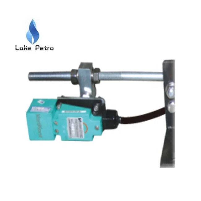
The Magneto® Pump Stroke Sensor is the latest new product from ASD Holdings (Advanced Sensor Design). ASD has successfully introduced unique products for the Oil & Gas Industry for over a decade. In this newest creation we find that the Magneto® Pump Stroke Sensor has been patented by Advanced Sensor Design. It is the world’s first pump stroke sensor that is mounted to the outside housing of the rig pump. It is mounted and stays in place by the use of a heavy duty magnet. The Magneto PSS is completely capable of detecting and counting Oil Rig “mud pump piston strokes” without having to make or be in contact with the pistons.
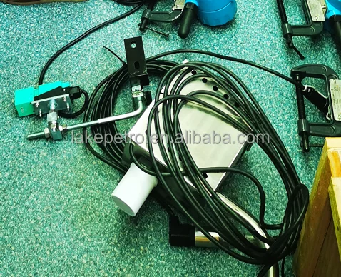
It is no longer a requirement to open the covers of the Oil Rig mud pumps to install a C-clamp style micro switch with a metal whisker. (Note picture below labeled C-clamp style micro switch) No longer is it necessary to bore a hole through the pump housing in order to get a proximity switch close enough to a piston to count actual strokes. (Note picture below labeled Cable going through pump housing) The Magneto® Pump Stroke Sensor is simple to install and easy to monitor!
The magnetic base of the Magneto® PSS makes it totally different than anything available in the marketplace today relative to its form and fit. However, that is not its only outstanding feature. Advanced Sensor Design is using “State of the Art” electronic circuitry that has the ability to give the end user (Oil Rig Mud Pump Operator) an On/Off switch type electrical output. Just like what the conventional mud pump sensors emit today. The obvious benefit to the oil rig is that No Special accommodations to their Data Acquisition Systems are required.

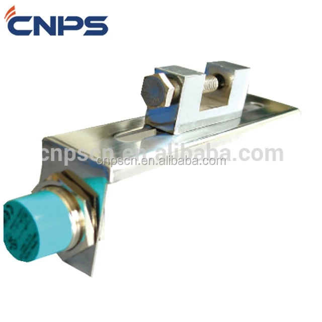
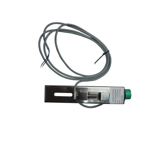
1.The pumping sensor can be fixed to the mud pump head by the bracket, or the appropriate part of the turntable, and the closest distance between the position of the sensing surface of the measured object and the end surface of the sensor is within 30 mm. (According to the influence of the use environment, the rated working distance is generally taken. 80%), plus the working voltage, when the end of the inductive sports sensor is close, the indicator light is on; when away from the sensor, the indicator is off.
2.The turntable speed sensor can be fixed to the appropriate part of the drive shaft of the turntable with the bracket. It should be convenient to install and repair. The model of the drill is selected. A piece of iron with a length and width of 30mm is welded on the shaft of the drive shaft or the airbag clutch. The position of the end face should be close to the end face of the sensor. Adjust the fixing nut of the sensor so that the distance between the iron sensor is within the effective range of the working distance.

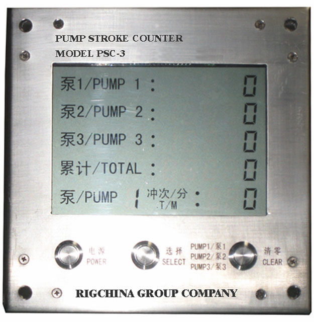
The RIGCHINA Pump Stroke Counter/Rate Meter displays both the total number of strokes and the strokes per minute for 3 mud pumps up to 1,024 strokes per minute for each pump. Push buttons conveniently located on the front of the instrument make it easy for the operator to reset each pump count

The SK-8Y2X series alloy film sensor consists of an ion-beam sputtering alloy film sensor and a signal modulation circuit and is applicable to detection of fluid pressure, differential pressure or liquid level. The Sensor is made using the modern film equipment and etching technique. The sensor has unique technique and excellent performance and can stably run in severe environment. The liquid medium pressure/differential pressure acts on the corrosion resistant stainless steel elastic film to deform the film, as shown in the strain schematic diagram. An alloy film strain resistance comprising Wheatstone bridge has been made on the film. Film deformation changes the geometry and value of the resistance, and the bridge outputs corresponding electrical signals. The electronic circuit amplifies the bridge output signals and converts them into standard 4~20mA current signals for output.
The pump stroke counter is used for measuring the number of pump strokes and per minute number of pump strokes (i.e. the frequency of pump strokes) of a reciprocation mud pump so to provide for the drill operators an accurate adding amount and speed of the mud to be grouted into a well shaft. It is a necessary meter in drilling process. Model BC-200A pump stroke counter comes out from improving the model BC 100 pump stroke counter, being a kind of updating and upgrading product of BC-100 pump stroke counter. Compared with BC-100, it increases a signal input channel and increases the functions of the count and accumulation of the pump strokes of a single channel, the total accumulation of the number of pump strokes, data memory when the machine is turned off, etc. Also its operation is even more convenient, simple and reliable. The totally enclosed structure, water-proof signal connectors and keys endow the BC-200A pump stroke counter with good moisture-proof and water-proof performance. After being subjected to a water-proof test for 12 hours under water with a depth of 1m, the BC-200A pump stroke counter shows so good water-proof performance that no water is found entering in. furthermore, with its overall power consumption being around 150uA, its sensor signal current around 5uA, the BC-200A pump stroke counter is actually explosion-proof, that is, it is intrinsically safe.

Conventional primary well control involves ensuring the column of mud filling the wellbore can exert a pressure that exceeds the highest pore pressure in any of the exposed formations below the last cemented casing shoe. The mud column then forms an effective primary well control barrier.
However, it may not be obvious that the mud column pressure is insufficient when drilling a very tight, low permeability shale formation. Hence, since pre-drill formation pore pressure predictions can only provide an estimate of the pore pressure profile along the planned well path, the planned mud weight may prove to be too low to prevent a kick from the next porous and permeable formation drilled below the shale.
During well operations the rig team focuses on maintaining the required primary well control barrier. This means following the mud weight plan and keeping the hole full of drilling mud.
If there are any problems with maintaining the primary barrier, the rig team has the authority to stop operations and address any problems with the primary barrier. For example, to stop downhole mud losses as quickly as possible that could compromise the ability of the rig team to keep the hole full of mud.
During tripping operations, the drillstring volume removed from the wellbore must be continuously replaced by the corresponding volume of weighted mud in order to keep the hole full. To facilitate this, most drilling rigs now pump mud through a fill line into the top of the well at a rate that always keeps the hole full. The excess mud returns are routed to a trip tank that feeds the fill pump, thus allowing the change in trip tank volume to be periodically compared to the drillstring volume removed from the hole.
This simplified illustration of the surface mud system and trip tank arrangement found on most conventional land, jack-up or platform rigs will help me explain what rig teams monitor in order to detect a fluid influx or kick.
During Drilling & Circulating drillers are taught that a kick will first of all increase the flow out before it will also cause an increasing level in the active mud pits.
During Tripping in or Out drillers are taught that a kick will result in an excess volume of mud in the trip tank compared to the calculated drillstring volume removed from the well.
Beyond kick detection, the time it takes to shut-in the well will allow more influx to flow from the formation into the wellbore . The intensity of the kick is one of the key factors that will increase the kick volume during the shut-in process. Kick intensity is the equiv. incremental mud weight, above the current mud weight, required to balance the pore pressure of the kicking formation.
Plotting the current Kick Tolerance limit on this same plot for a worst case gas influx when pumps stopped for a connection, shows that this example shut-in influx volume could be large enough to rupture the formation close to the last casing shoe.
For kick detection the driller will have a flow-out gauge and a pit volume gauge. For each of these gauges he will be able to set deviation alarms for an increase (or a decrease) from the stable values he sees when he is drilling ahead with pumps running.
Unfortunately, this style of basic kick (and loss) detection instrumentation results in multiple alarms being triggered each time the pumps are shut-down to make a connection. As a result, the annoyingly loud audible alarm triggered by this type of kick (and loss) detection instrumentation is often disabled by the driller.
This example shows how an adaptive alarm scheme does not generate any alarms due to normal operations (including 3 connections and a change in pump rate) and has no trouble initiating an influx alarm.
The results of the fault tree sensitivity analysis are reported here in terms of the performance improvement vs. the Base case. From this table it is clear that the biggest improvement in kick detection and shut-in performance (16.9%) was predicted to be from including Best Sensors. Adding Smart Alarms resulted in a smaller, but still significant, additional performance improvement of 9.1%. Perhaps the most surprising result of the analysis was that the predicted incremental performance improvement from adding Automated Shut-in was only 1.3%. However, this may be attributable to the Driller’s high degree of kick detection and well shut-in competency assumed in the Base Case analysis.
For mud flow-in sensors, “best practical” sensor technology might look like this. With duplication provided by pump strokes and coriolis meters for each pump.
Note that in some installation configurations the mud can drain out of the coriolis meter when the corresponding mud pump is stopped. To avoid transmitting spurious coriolis flow-in data for a stopped mud pump, one operator had to add an on/off filter to the coriolis data stream based on pump strokes. Hence, demonstrating the value of having two sensors to measure flow-in that use different technology.
For mud flow-out sensors, “best practical” sensor today is a coriolis meter for rigs that can accommodate the return flowline modifications required, in this case a jack-up rig. However, I’m not aware of any field implementations where a second flow-out sensor has been installed with a coriolis meter to help mitigate the sensitivity of corioils meters to small amounts of entrained gas. Note that most deepwater drillships and many semi-submersible rigs cannot accommodate a coriolis meter in the return flowline due to the available fluid head from the diverter to the gumbo box being too small to drive fluid through a correctly sized coriolis flow meter.
The typical flow sensor configuration on most rigs (land or offshore) is stroke counters for flow-in and a paddle flow sensor for %flow-out. A radar flow-out sensor to measure fluid height in the mud return flowline is typically installed by the mud logging service company on deepwater rigs when they are providing real-time drilling data services. Since accurate flow-in vs. flow-out measurements are important for early kick detection, during both drilling and making connections, there is obviously plenty of scope for further development of “best practical” flow-in and flow-out sensor technology for implementation on the majority of drilling rigs.
Ultrasound technology based flow sensors are already being used successfully for low density fluid flow measurement and the technology is now being investigated for developing weighted mud flow sensors, both for flow-in and flow-out applications.
To better eliminate pitch and roll effects, two pairs of level sensors are typically required for each pit mounted in opposite corners diagonally across from each other. Non-contacting (open path) radar sensors are the most practical level sensors to use for this application as they only require access to the top of the mud pit for installation.
One of the challenges of retro-fitting all the pits on any floating rig with four sensors is that the level measurement sensors must be placed at a minimum separation distance from mud guns, walls, pipes and agitators inside the pit while also considering the location of piping and walkways on top of the pit. Overall this may not allow optimal placement of all four level sensors close to each corner, as shown here for this example level sensor upgrade for Active pits 1 & 2 on a deepwater semi-submersible.
For this example level sensor upgrade, averaging the output from all four pit level sensors was effective in de-coupling natural rig motions (such as pitch and roll) from the measured total active pit volume. Before the upgrade any crane usage had to be suspended when drilling ahead (to prevent spurious pit level fluctuations). After the upgrade, the added sensors not only neutralized normal rig motions but also permitted free use of all cranes without any interference to accurate active pit volume monitoring.
CLICK For kicks detected during a connection (after rig pumps are turned off) the pop-up gives the crew a tool to compare the flow out “finger print” signature for the current connection (shown in red on the RH plot) with the last five connections. Based on the displayed “finger print” information, the driller can make a better informed decision.
In summary at about 07.47 am the driller began to decrease the mud pump strokes to zero in preparation for another connection. A flow check was then conducted by the drill crew. From previous connections, the average pumps-off time for return flow to decrease to zero had been 90 seconds. The Driller waited the normal 90 seconds and then asked a member of the drill crew to perform a visual flow check. The crew member reported continuous flow and the Driller reacted by shutting-in the well. A few minutes later the Driller successfully completed the well shut-in operation.
The first positive indication of an influx occurred just seconds before the pumps were shut-down, based on the small detected increase in return flow that triggered the new audible kick alarm and the corresponding new pop-up Kick Monitor Display. However, since the Driller was ready to make a connection, the Driller simply acknowledged the “Flow Increase while drilling” alarm and proceeded with the planned flow check that was part of the routine connection procedure he was using.
Therefore it was felt that a separate internal development to create robust kick detection software for influx detection at pumps stopped (or IDAPS) was needed. The resulting IDAPS monitoring display is shown here.
To date all verified influxes that occurred after a pump shut-down have been detected by IDAPS. Hence, PD has been demonstrated to be 100% and fully satisfied the target value.
The Two-pump Digital Stroke Rate Meter monitors and displays the Rate and Total Strokes of up to two individual pumps simultaneously. The unit continually displays, on large easy to read, low power LCD displays, RPM, TOTAL ACCUMULATED STROKES (0-9999 total strokes) and STROKE RATE (8-350 strokes per minute) for each pump. The unit is internally powered by a battery source having an operational life of 3 years.
At Matherne Instrumentation, we"re proud to provide both our two-pump and three-pump stroke counters to companies and oilfield operators across the states of Texas, Louisiana, North Dakota, and Pennsylvania. While our offices are based in Odessa, TX; Lafayette, LA; and Houma, LA, we"re proud to serve those across the cities of Midland, TX; Houston, TX; Williston, ND; and Pittsburgh, PA. To learn more or for a quote, please feel free to give us a call today!
Coriolis mass flow sensors are increasingly being used by drilling operators to measure drilling fluid density and flow-rate parameters in real time, whether on sixth-generation drillships or 30-year-old land rigs. Collecting density and flow-rate data in real time is helping to lower drilling costs by reducing nonproductive time (NPT) and identifying leading indicators to potential operational problems, which contributes to real-time drilling optimization.
The real-time data can be aggregated into the rig control system to display graphics with built-in alarm functionality, providing the driller and mud engineer with advanced notice of major changes to drilling parameters.
Until recently, density and flow rate were not parameters that the rig control system measured in real time. Traditionally the mud pump stroke count was used to calculate flow rate entering the well, and density was measured by the derrickman or mud engineer – often only twice an hour. Flow rate exiting the well was normally measured using a paddle wheel-type of device that generally indicated only a percentage of flow in the flow line. Density was measured every 30 minutes from a sample point downstream of the shakers.
A Coriolis meter can be mounted in-line between the active mud tank and the mud pumps to measure fluid going into the well. A second Coriolis meter can be installed at the flow line to measure the fluid exiting the well. The cumulative mass of cuttings can be metered coming out of the hole to provide an electronic means of doing what has traditionally been referred to as “keeping an eye on the shakers.”
Integrating the data accuracy and reliability of these two sensors into a real-time wellbore monitoring system process can provide drillers and mud engineers with a “live” tool to help mitigate problems in:
This data can be graphed on the same plot as the mass flow of rock generated at the bit. The real-time stream of data could provide the drillers and mud engineers with accurate information to help mitigate a potential drilling problem before it happens.
Common problems that could be more effectively managed through this concept include stuck pipe, excessive torque and drag, annular packoff, increased equivalent circulation density, loss circulation, excessive viscosity and gel strengths, poor casing and cement jobs, high mud dilution costs and slower drilling rates.
Uncertainty in identifying the oil/water interface during a synthetic-based mud (SBM) wellbore displacement can result in unnecessary volumes of fluid being generated for treatment and disposal.
Coriolis meters can aid in environmental compliance monitoring by helping the mud engineer minimize the volume of “slops” generated during SBM displacement operations. Normally a weighted brine pill or spacer is pumped ahead of the SBM. Once the brine pill is displaced back to surface, the SBM/water interface will be monitored and can help the mud engineer to identify the optimum time to close in the system (Figure 7).
Real-time, accurate and reliable fluid volume measurements are required to recognize and mitigate fluid losses and kicks. Comparing pump strokes for downhole flow rates to paddle meters on the return side or mud pit level presents several challenges to the accuracy, reliability and lag times in recognizing barrels in barrels out volume changes.
Comparing the return flow out of the well to either pumps stroke volumes or to another Coriolis meter on the suction side of the mud pump can provide an effective means to monitor formation losses.
The same in and out Coriolis flow data can be used for enhanced kick detection. Current practices involve comparing pump stroke-based volume to returns flow and is commonly used in managed pressure drilling systems. The same application is being applied to conventional and rotary head rigs where hydrostatic pressure in the returns line is used to maintain flow in the meter.
Coriolis meters can also help to monitor ballooning. The deepwater phenomenon of ballooning has been identified as the slow loss of mud while drilling ahead, followed by a more rapid mud return after the pumps have been turned off.
Researchers have shown that mud pulse telemetry technologies have gained exploration and drilling application advantages by providing cost-effective real-time data transmission in closed-loop drilling operations. Given the inherited mud pulse operation difficulties, there have been numerous communication channel efforts to improve data rate speed and transmission distance in LWD operations. As discussed in “MPT systems signal impairments”, mud pulse signal pulse transmissions are subjected to mud pump noise signals, signal attenuation and dispersion, downhole random (electrical) noises, signal echoes and reflections, drillstring rock formation and gas effects, that demand complex surface signal detection and extraction processes. A number of enhanced signal processing techniques and methods to signal coding and decoding, data compression, noise cancellation and channel equalization have led to improved MPT performance in tests and field applications. This section discusses signal-processing techniques to minimize or eliminate signal impairments on mud pulse telemetry system.
At early stages of mud pulse telemetry applications, matched filter demonstrated the ability to detect mud pulse signals in the presence of simulated or real noise. Matched filter method eliminated the mud noise effects by calculating the self-correlation coefficients of received signal mixed with noise (Marsh et al. 1988). Sharp cutoff low-pass filter was proposed to remove mud pump high frequencies and improve surface signal detection. However, matched filter method was appropriate only for limited single frequency signal modulated by frequency-shift keying (FSK) with low transmission efficiency and could not work for frequency band signals modulated by phase shift keying (PSK) (Shen et al. 2013a).
In processing noise-contaminated mud pulse signals, longer vanishing moments are used, but takes longer time for wavelet transform. The main wavelet transform method challenges include effective selection of wavelet base, scale parameters and vanishing moment; the key determinants of signal correlation coefficients used to evaluate similarities between original and processed signals. Chen et al. (2010) researched on wavelet transform and de-noising technique to obtain mud pulse signals waveform shaping and signal extraction based on the pulse-code information processing to restore pulse signal and improve SNR. Simulated discrete wavelet transform showed effective de-noise technique, downhole signal was recovered and decoded with low error rate. Namuq et al. (2013) studied mud pulse signal detection and characterization technique of non-stationary continuous pressure pulses generated by the mud siren based on the continuous Morlet wavelet transformation. In this method, generated non-stationary sinusoidal pressure pulses with varying amplitudes and frequencies used ASK and FSK modulation schemes. Simulated wavelet technique showed appropriate results for dynamic signal characteristics analysis.
As discussed in “MPT mud pump noises”, the often overlap of the mud pulses frequency spectra with the mud pump noise frequency components adds complexity to mud pulse signal detection and extraction. Real-time monitoring requirement and the non-stationary frequency characteristics made the utilization of traditional noise filtering techniques very difficult (Brandon et al. 1999). The MPT operations practical problem contains spurious frequency peaks or outliers that the standard filter design cannot effectively eliminate without the possibility of destroying some data. Therefore, to separate noise components from signal components, new filtering algorithms are compulsory.
Early development Brandon et al. (1999) proposed adaptive compensation method that use non-linear digital gain and signal averaging in the reference channel to eliminate the noise components in the primary channel. In this method, synthesized mud pulse signal and mud pump noise were generated and tested to examine the real-time digital adaptive compensation applicability. However, the method was not successfully applied due to complex noise signals where the power and the phases of the pump noises are not the same.
Jianhui et al. (2007) researched the use of two-step filtering algorithms to eliminate mud pulse signal direct current (DC) noise components and attenuate the high frequency noises. In the study, the low-pass finite impulse response (FIR) filter design was used as the DC estimator to get a zero mean signal from the received pressure waveforms while the band-pass filter was used to eliminate out-of-band mud pump frequency components. This method used center-of-gravity technique to obtain mud pulse positions of downhole signal modulated by pulse positioning modulation (PPM) scheme. Later Zhao et al. (2009) used the average filtering algorithm to decay DC noise components and a windowed limited impulse response (FIR) algorithm deployed to filter high frequency noise. Yuan and Gong (2011) studied the use of directional difference filter and band-pass filter methods to remove noise on the continuous mud pulse differential binary phase shift keying (DBPSK) modulated downhole signal. In this technique, the directional difference filter was used to eliminate mud pump and reflection noise signals in time domain while band-pass filter isolated out-of-band noise frequencies in frequency domain.
Other researchers implemented adaptive FIR digital filter using least mean square (LMS) evaluation criterion to realize the filter performances to eliminate random noise frequencies and reconstruct mud pulse signals. This technique was adopted to reduce mud pump noise and improve surface received telemetry signal detection and reliability. However, the quality of reconstructed signal depends on the signal distortion factor, which relates to the filter step-size factor. Reasonably, chosen filter step-size factor reduces the signal distortion quality. Li and Reckmann (2009) research used the reference signal fundamental frequencies and simulated mud pump harmonic frequencies passed through the LMS filter design to adaptively track pump noises. This method reduced the pump noise signals by subtracting the pump noise approximation from the received telemetry signal. Shen et al. (2013a) studied the impacts of filter step-size on signal-to-noise ratio (SNR) distortions. The study used the LMS control algorithm to adjust the adaptive filter weight coefficients on mud pulse signal modulated by differential phase shift keying (DPSK). In this technique, the same filter step-size factor numerical calculations showed that the distortion factor of reconstructed mud pressure QPSK signal is smaller than that of the mud pressure DPSK signal.
Study on electromagnetic LWD receiver’s ability to extract weak signals from large amounts of well site noise using the adaptive LMS iterative algorithm was done by (Liu 2016). Though the method is complex and not straightforward to implement, successive LMS adaptive iterations produced the LMS filter output that converges to an acceptable harmonic pump noise approximation. Researchers’ experimental and simulated results show that the modified LMS algorithm has faster convergence speed, smaller steady state and lower excess mean square error. Studies have shown that adaptive FIR LMS noise cancellation algorithm is a feasible effective technique to recover useful surface-decoded signal with reasonable information quantity and low error rate.
Different techniques which utilize two pressure sensors have been proposed to reduce or eliminate mud pump noises and recover downhole telemetry signals. During mud pressure signal generation, activated pulsar provides an uplink signal at the downhole location and the at least two sensor measurements are used to estimate the mud channel transfer function (Reckmann 2008). The telemetry signal and the first signal (pressure signal or flow rate signal) are used to activate the pulsar and provide an uplink signal at the downhole location; second signal received at the surface detectors is processed to estimate the telemetry signal; a third signal responsive to the uplink signal at a location near the downhole location is measured (Brackel 2016; Brooks 2015; Reckmann 2008, 2014). The filtering process uses the time delay between first and third signals to estimate the two signal cross-correlation (Reckmann 2014). In this method, the derived filter estimates the transfer function of the communication channel between the pressure sensor locations proximate to the mud pump noise source signals. The digital pump stroke is used to generate pump noise signal source at a sampling rate that is less than the selected receiver signal (Brackel 2016). This technique is complex as it is difficult to estimate accurately the phase difference required to give quantifiable time delay between the pump sensor and pressure sensor signals.
As mud pulse frequencies coincide with pump noise frequency in the MPT 1–20 Hz frequency operations, applications of narrow-band filter cannot effectively eliminate pump noises. Shao et al. (2017) proposed continuous mud pulse signal extraction method using dual sensor differential signal algorithm; the signal was modulated by the binary frequency-shift keying (BFSK). Based on opposite propagation direction between the downhole mud pulses and pump noises, analysis of signal convolution and Fourier transform theory signal processing methods can cancel pump noise signals using Eqs. 3 and 4. The extracted mud pulse telemetry signal in frequency domain is given by Eqs. 3 and 4 and its inverse Fourier transformation by Eq. 4. The method is feasible to solve the problem of signal extraction from pump noise,
\(H(\omega )={f^{ - 1}}h(t)=G(\omega ){e^{ - j\omega \tau }}\) is the Fourier transformed impulse response, \(h(t)\), data transmission between sensor A and sensor B.
These researches provide a novel mud pulse signal detection and extraction techniques submerged into mud pump noise, attenuation, reflections, and other noise signals as it moves through the drilling mud.
Forum Compound Pointer Pressure Gauge systems accurately measure and display pump pressures for downhole cementing, high-pressure hydraulic fracturing, or acidizing oil pay operations.


 8613371530291