
mud pump suction stabilizer factory
The reciprocating pump’s cylinders pull its fluids from the suction manifold. When the suction manifold has trouble refilling with fluid, the cylinders will take in vapor and create a void in the cylinder. This is called cavitation, and it produces a very adverse reaction that is transferred into the fluids.
When you install a suction stabilizer off the suction manifold port, this gives the manifold extra capacity to pull fluid from and eliminates the manifold’s opportunity to lack fluids, thus eliminating cavitation.
The second benefit the suction stabilizer offers is eliminating negative forces in the fluids produced by the pump’s valves opening and closing rapidly, creating a water hammer effect. The suction stabilizer’s compressible element is designed to absorb these energies and smooth out the fluid flow. This causes pump isolation or, in other words, the reciprocating pump is now isolated from the charge pump, and vice versa. The negative energies produced by the reciprocating pump never make it back to the charge pump, which extends the life of the pump expendables.
This invention relates to an improved suction stabilizer for reciprocating pumps and to an improved method of stabilizing the inflow of liquid to the suction side of a reciprocating pump.
A reciprocating pump alternately undergoes suction strokes and discharge strokes which draw liquid into its cylinders and force the liquid therefrom. Hence the pump is a variable demand mechanism, but usually it is fed from a source of liquid under a constant head. Ideally a reciprocating pump is fed from a large head located immediately adjacent its suction side, but most layouts do not provide this. Long lines or small diameter lines leading from the source to the suction side of the pump, or turns or fittings in the line, or low head or volatile liquids, for example, create poor suction conditions. One result of poor suction conditions is that the pump cylinders do not fill completely, and the pump operates less efficiently.
To improve poor suction conditions, it is known to install a stabilizer at the suction side of a reciprocating pump. For exemplary showings of suction stabilizers used heretofore, reference can be made to Day U.S. Pat. No. 2,712,831, Wilson U.S. Pat. No. 2,934,025, Cornelsen U.S. Pat. No. 3,146,724 or Zahid U.S. Pat. No. 3,782,418. Accumulators which comprise a tank and a gas filled bladder within the tank are well known for use on the discharge side of reciprocating pumps. Reference can be made to any of several patents to E. M. Greer, for example U.S. Pat. Nos. 3,211,348, 3,494,378 or 3,593,746, for showings. Accumulators of such construction have been installed as stabilizers on the suction side, but have not proved effective.
An object of my invention is to provide an improved suction stabilizer and stabilizing method which are more effective in stabilizing inflow of liquid to a reciprocating pump than stabilizers and stabilizing methods used heretofore.
A further object is to provide an improved bladder-type stabilizer and stabilizing method in which the ratio of tank volume to pump displacement per revolution is at least ten to one, and the ratio of tank volume to bladder volume is at least four to one, values which I have found to be critical for obtaining optimum stabilization of liquid flow from a source into a pump.
A further object to provide an improved stabilizer and stabilizing method which enable gas entrained in the liquid from the source to be removed before the liquid enters the pump.
FIG. 1 is a diagrammatic end elevational view of a quintuplex reciprocating pump equipped with one form of suction stabilizer constructed in accordance with my invention;
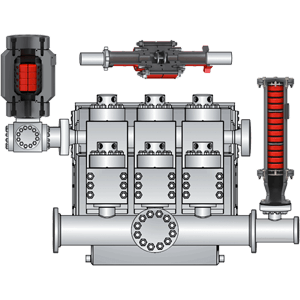
FIG. 1 shows a conventional reciprocating pump, for example, a slurry pump, a mud pump used in well drilling, or pipe-line pump, or other type. The pump illustrated is a quintuplex which comprises a plurality of cylinders 10, a suction manifold 12 and a discharge manifold 13. The reciprocating elements of the pump are driven through a crankshaft and connecting rods or the like of any standard or desired constuction, and they draw liquid into each cylinder in turn from the suction manifold, and force the liquid from each cylinder in turn into the discharge manifold. The pump of course has the usual inlet and discharge valves which open and close between strokes. In the interest of simplicity, the drive and valves are not shown. An inlet line 14 extends from a source of liquid, and is connected to the suction manifold 12 through a suction stabilizer 15 constructed in accordance with my invention.
FIG. 2 shows a form of stabilizer 15 which I prefer for clean liquids and which includes a cylindrical tank 18, a cage 19 within the tank fixed to its upper end wall, a bladder 20 of flexible resilient material (for example rubber) within the cage, and a transverse baffle 21 within the tank spaced beneath the cage. In this form the tank is positioned with its longitudinal axis vertical. The bladder is suspended from a removable cover 22 for the cage. The cage walls are perforate to permit liquid to contact the outside of the bladder, but prevent the bladder from wobbling. The tank has an inlet 23 and a diametrically opposed outlet 24 in its side walls. Baffle 21 extends vertically diametrically of the tank from adjacent the bottom thereof to a height substantially above the inlet and outlet, whereby liquid passing through the tank passes over the top of the baffle. The inlet and outlet have pressure taps 25 and 26 respectively. The tank has a vent 27 in its top and a drain 28 in its bottom.
FIG. 3 shows a modified form of stabilizer which I prefer for liquids containing an appreciable content of solid particles, such as muds or slurries. In this form I eliminate the baffle, since a baffle may act as a dam or it may wear rapidly on being struck by solid particles. Instead I locate the inlet 23 and outlet 24 in some relation other than in direct alignment, whereby the direction of flow of the liquid changes as the liquid passes through the tank. The effect is much the same as that obtained with a baffle, as hereinafter explained. In other respects, this stabilizer is constructed similarly to the form shown in FIG. 2; hence I do not repeat the showing or description.
FIG. 4 shows a modification in which the stabilizer 31 itself serves as a suction manifold. The stabilizer is positioned beneath the pump with the longitudinal axis of its tank extending horizontally. The side walls of the tank have an inlet 32 and a plurality of outlets 33 leading the respective cylinders of the pump. The outlets are out of alignment with the inlet, as in the form shown in FIG. 3. The cage and bladder are similar to those used in the form shown in FIG. 2, except that they are mounted on an end wall of the tank.
FIG. 5 shows another modification in which the stabilizer 34 is positioned above the pump. In all other respects the form shown in FIG. 5 is similar to that shown in FIG. 4.
The present invention involves several novel and critical relations. The ratio of the tank volume to the pump displacement per revolution should be at least about ten to one. The pump of course has a given displacement per revolution of its drive. The ratio of the tank volume to the bladder volume should be at least about four to one when the bladder is inflated to its normal operating pressure. In referring to the "tank volume", I mean the volume of liquid which the tank may contain. In both instances there is no harm if the foregoing ratios are exceeded, but little advantage. The bladder is inflated with gas, preferably nitrogen, to an initial pressure in the range of about 40 to 60% of the suction pressure as can be determined at the pressure tap 26 (FIG. 2).
In operation, (with reference to FIGS. 1 and 2) the tank 18 fills with liquid introduced via inlet 23. As the liquid passes through the tank, its direction of flow changes as it passes over the baffle 21. The liquid passes from the tank via the outlet 24 into the suction manifold 12. Between suction strokes of the pump, liquid entering the tank compresses the gas within the bladder 20. During each suction stroke pressure of gas within the bladder adds to the head on the liquid entering the pump and assures a smooth flow of liquid into the pump, whereby each cylinder in turn fills completely. Liquid moves continuously from the source, not merely when the pump undergoes suction strokes. As the direction of flow changes, any gas entrained in the liquid tends to separate out and collect in the upper portion of the tank. When an appreciable volume of gas has accumulated, I open vent 27 to release the accumulation. The vent can be opened either manually or periodically open automatically.
FIG. 6 shows graphically the way in which both the pressure in one cylinder and the pressure in the suction manifold vary during one cycle of one cylinder in a quintuplex pump constructed as shown in FIG. 1 operating with good suction conditions but without a stabilizer. The upper graph shows the cylinder pressure, which is atmospheric or zero gauge during the suction stroke and rises to a slightly uneven plateau during the discharge stroke, as indicated at A and B respectively. The sloping portions of the curve represent the periods during which the valves are opening and closing. The lower graph resolves the suction manifold pressure into two component curves C and D. Curve C, shown in solid lines, represents the pressure waveform generated by the closing of each suction valve. Ideally this curve is in the form of a series of smoothly diminishing sine waves, the amplitude of which reach a maximum at the instant each suction valves closes. This pressure variation results from a "ringing" effect as the valve closes. Curve D shown in dotted lines, represents the wave form generated by pump displacement. If suction conditions are poor, both curves become highly irregular.
Addition of a properly designed suction stabilizer assures that curve C takes the form illustrated in FIG. 6. The stabilizer does not improve the shape of this curve when compared with a pump which operates under good suction conditions without a stabilizer, but assures that suction conditions become good if they are not already. Addition of a properly designed suction stabilizer eliminates curve D. The pump displacement pressure becomes constant, or nearly so.
From the foregoing description, it is seen that my invention affords a simple suction stabilizer and stabilizing method which assure good suction conditions at the suction side of a reciprocating pump. The various ratios and the pressure relation listed hereinbefore are novel and critical to achieving optimum results. The arrangement of FIGS. 1, 2 and 3 offers the advantage of providing a greater head on the liquid entering the suction manifold than the arrangement of FIGS. 4 and 5.
Performance Pulsation Control is meeting the suction stabilizer needs of clients across the country. We can tailor a suction stabilizer and suction pulsation dampener to fit the specific output requirements of any commercial industry that relies on consistent and precise pump solutions. Some of the customization possibilities you’ll find for your business applications include:
Buy high-capacity pump suction stabilizer that are guaranteed to keep your appliances up and running in perfect condition from Alibaba.com. These pump suction stabilizer are offered from the best and most energy-efficient brands and provides users with an elevated experience. These pump suction stabilizer are designed to ensure safety and stability and are available in a number of variants.
pump suction stabilizer offered on Alibaba.com have many necessary and interesting features such as fail-safe circuit protection and cut-off points. These pump suction stabilizer have a high range and are likely to fit most home and commercial purposes. These pump suction stabilizer have finely crafted exteriors to ensure that there is no risk of shock or accidents. Some of these items even have LED displays for a smoother experience and greater transparency.
pump suction stabilizer are suitable for all sorts of large appliances and do not malfunction easily. They require very limited maintenance and not much has to be spent on their upkeep. pump suction stabilizer ensure that your expensive appliances and machines do not get damaged due to fluctuations and are inevitable for any home or commercial enterprise that engages multiple electronic items. pump suction stabilizer on the site offer optimal performance at economical prices.
Choose the pump suction stabilizer that best suit your needs, whether for home, office or industry. pump suction stabilizer suppliers are sure to want to snap up this attractive chance to buy quality items at discounted prices. Grab these amazing deals today.
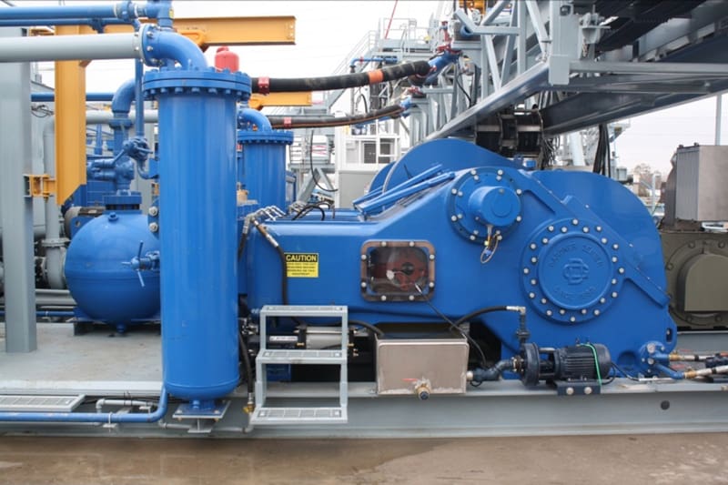
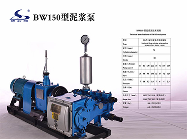
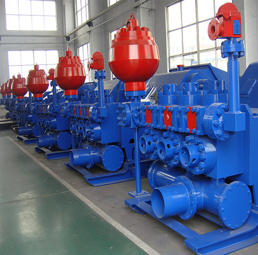
F2000 triplex piston mud pumps are firm and compact in structure and small in size, with good functional performances, which can adapt to drilling technological requirements such as oilfield high pump pressure and large displacement etc. The F series mud pumps can be maintained at lower stroke rate for their long stroke, which effectively improves the feeding water performance of mud pumps and prolongs the service life of the fluid end. The suction stabilizer, with advanced structure and reliable service, can achieve the best buffering effect. Power ends of the F series mud pumps adopt the reliable combination of forced lubrication and splash lubrication to increase the service life of power ends.
Pulsation problems often start on the suction side. Pulsation or cavitation is caused by the variation of fluid movement within a contained system. Since fluid is non-compressible, the energy produced by this pulsation or cavitation must be compensated for. With the introduction of pulsation equipment into a system this energy now has a place to expend itself. Without the pulsation equipment involved in your pumping system, the pulsation or cavitation that is present can lead to the following:

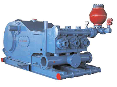
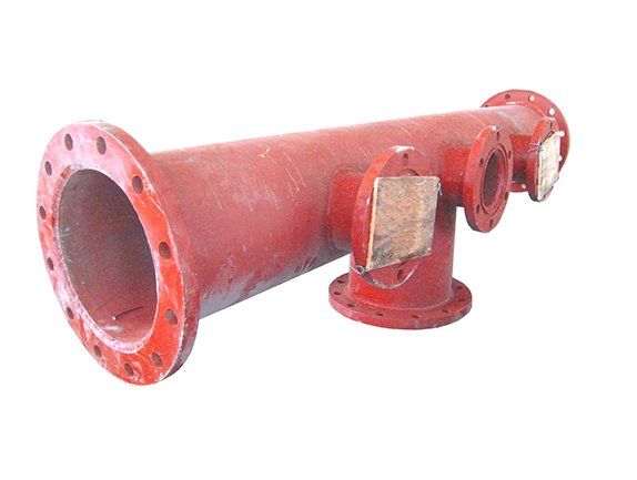
In order to reduce the fluctuation of pressure and displacement of the drilling mud pump, air bag are usually installed on the discharge line. The air bag manufactured by our company has advanced structure and reliable performance, which can make the mud pump achieve the best inhalation effect and is widely used in petroleum, high-pressure pipeline of chemical transportation. This product can also be used as a stabilizer and shock absorber for air extractors.
The pulsation dampener can be divided into discharge pulsation dampener and Suction Dampener.Discharge pulsation dampener- reduces displacement of pump and fluctuation of pressure.
In order to reduce the pressure and displacement of drilling mud pumps, air bags are usually installed on the discharge pipeline. The suction air bags produced by our company have advanced structure and reliable performance, which can make the mud pump achieve the best suction. The effect is widely used in high-pressure pipelines for petroleum and chemical transportation. It can balance the peak pressure of high-pressure fluid in mud pumps, stabilize the pressure, and reduce losses. This product can also be used as a stabilizer and shock absorber for air extractors.
The mud pump is installed on the discharge line, which can balance the peak pressure of the high pressure fluid of the mud pump, play a role in stabilizing the pressure, reducing losses and ensuring safety, so that the mud pump can achieve the best suction effect.
Drain buffer: Installed at the drain end of pumps and compressors, it can avoid fatigue damage of cylinder pistons, valves, bases and pipelines due to pressure fluctuations, thereby extending the service life of the equipment.
Absorption of oscillation: The opening of the valve in the fluid system and the sudden closing of the valve for various other reasons will cause a huge impact pressure to form a water hammer phenomenon, causing the rupture of the pipe and the pipe seat and the damage to the downstream equipment. After installing the suction air bag, it can act as a buffer to avoid this phenomenon.
Reverse Oscillation: When the head of the water pump reaches a certain height, the reverse oscillation caused by the impact of the fluid into the pump valve will cause the pump to suddenly shut down. A suction air bag is installed to absorb part of the vibration.
For a petrochemical plant, customer ordered an Air Operated Double Diaphragm pump to lift water from an underground pit for intermittent application. The pit was 5 meter deep and customer had to mount the pump on the ground level. The flow required was 5 m3/hr and they were draining the water to close by pipeline with 10 meter head. 1” Aluminum pump with Buna diaphragm was selected.
During detail engineering, one of the pump expert remarked, “Pump may be able to lift the material but will not deliver the required flow.” What did everyone else seems to miss that the expert got?
Positive displacement pumps- few rotary and all reciprocating type- create pulsating flow. These flow pulses occur because the pump’s liquid chamber/s are repeatedly filled with liquid on the suction stroke and then pushed out on the discharge stroke. This pulsating flow results in damaging vibration, pressure surges, and increased noise.
Flow from a piston or diaphragm pump is not linear- it accelerates at the start of the pump stroke, reaches maximum velocity at the mid point, and decelerates to zero flow at the end of the stroke. While the flow is accelerating and decelerating, the fluid pressure at the pump’s discharge is increasing and decreasing. Peak flow from the pump can be as much as three time the average or mean flow, creating an acceleration head phenomenon.
The design and construction of a liquid pumping system is often concentrated on ensuring that the desired pressure and flow are achieved at the downstream of the pump. Frequently, pump inlet conditions are not given proper consideration in the system design. Given the acceleration head loss phenomenon, it is even more critical to include complete design analysis of pump inlet conditions for reciprocating pumps.
Net positive suction head available (NPSHA) is the pressure in the feet of liquid absolute measure at the pump suction port, less the vapor pressure. Hydraulic Institute specifies a measurement of procedure for NPSHR, which is at the point that a reciprocating pump loses 3.0% in volumetric efficiency relative to a stable efficiency at a high suction head. NPSHR must be supplied by the pump manufacturer. If the NPSHA is less than NPSHR, the pressure at some point in the suction area will be less than the vapor pressure of the liquid, cavitation will take place in the pump.
Acceleration head loss is frequently forgotten in calculating NPSHA. The liquid mass in the suction line to the pump must be started and stopped with every pump stroke. The pump must expend energy to accelerate the liquid into the pump during the suction stroke and then stop the inlet flow on the discharge stroke. This is acceleration head component of NPSHA for reciprocating pumps and can be calculated using below formula:
K = A factor representing the reciprocal of the fraction of the theoretical acceleration head which must be provided to avoid a noticeable disturbance in the suction line
NPSHA is more than NPSHR- so it should be acceptable. However, let’s calculate acceleration head loss- it’s more than 8 MWC- of course the pump will not deliver the required flow.
Move the pump as close as possible to the source of the supply to reduce the mass that must be reaccelerated on every stroke and to reduce friction loss
Standpipes provide an area of accumulation and release of pumped liquid as the pump’s inlet valve alternatively opens and closes. Typically, the stand pipe needs to be 1.5 times the diameter of the suction pipe line, as tall as the supply tank height, and mounted within 25 (preferably 10) pipe diameters from the pump’s suction. The standpipe must also be capped and typically vented to the supply tank. Therefore, it can’t be used on suction lift applications. The other problem with standpipes is that they can become waterlogged and rendered ineffective when trapped air at the top becomes entrained in the liquid accumulated in the standpipe.
Essentially a pulsation dampener, an inlet stabilizer has a flexible internal diaphragm or bladder to prevent mixing of the system liquid with the stabilizer’s gas charge. Properly sized and installed in a tee 10 pipe diameter of the pump inlet, it can usually reduce acceleration head loss to less than 3 to 4 psi. It does this by accumulating liquid during the pump’s discharge stroke and releasing the liquid back into the suction line during the pump’s inlet stroke. In effect, the inlet stabilizer uses the stored energy of the compressed gas to reaccelerate the liquid back into the suction line. It will only have an effect on the liquid between it and the pump inlet so proper location is critical. Special inlet stabilizers are available for suction lift applications
In conclusion, it is important to consider several factors related to inlet piping for positive displacement pumps, specifically reciprocating pumps and peristaltic (or hose) pumps. Acceleration head loss is very important element when calculating NPSHA. Since acceleration head loss depends on both system parameters (pipe diameter, length, liquid details etc) and pump sizing (stroke rate, pump type- single acting or double acting, no of heads), acceleration head loss calculations are often overlooked and misunderstood. With suitable system design at the pump inlet, which may include standpipe or inlet stabilizer, improved pump performance will be obtained by reducing acceleration head loss.


 8613371530291