
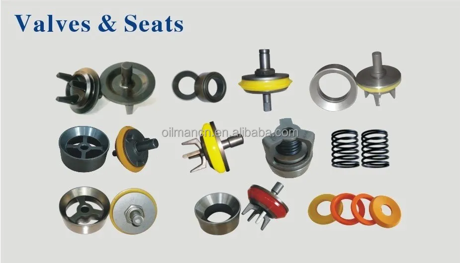
mud pump valve body free sample

My invention relates to valves of the character employed in mud pumps or other pumps adapted to pump fluid mixtures containing abrasive materials, and relates particularly to an improved form of such valve capable of longer periods of uninterrupted use than valves which are at present employed in pumps of this character.
Mud pump valves of the character to which my invention relates are subject to very rapid wear owing to the presence of abrasive materials, such -as fine particles of rocks, quartz, or sand contained in the drilling fluid or mud, and therefore must be replaced after comparatively short periods of use. Such valves ordinarily include a seat member consisting of an annular ring with a sealing seat near the upper end thereof and a spider structure across the lower portion thereof, and a valve element including a body of metal adapted to strike against the spider when the valve element is in lowered or relatively closed position and a sealing member on the metal body adapted to engage the sealing face of the seat member and prevent leakage of fluid through the valve when the valve is in its closed position. It is an object of my invention to provide a valve of the above character of simple construction yet being capable of giving a greater period of service than valves of complex structure.
It is an object of the invention to provide a valve having a seat member including an annular sealing face or seat and a valve closure member having a circular or annular sealing member of rubber material adapted to enter the space enclosed by the annular sealing seat or face of the seat member and to be deformed by fluid pressure so as to expand against the sealing face of the seat member.
It is a further object of the invention to provide a valve of the above character in which the cooperative parts are so formed that the sealing member preferably wipes the sealing face clean as it moves into closed position, thereby reducing to a minimum the particles of abrasive material which may rest between the sealing member and the sealing face, the result thereof being that the wear between these parts is minimized and the useful life of the valve materially extended.
It is a further object of the invention to provide a valve which may be used for abrasive subo5 stances and which may be also employed in pumps for circulating other fluids, such as crude oils.
It is a still further object of the invention to seal the valve by a sealing member on the valve body having a peripheral annular engagement surface adapted to be received within an annular inwardly faced sealing wall surface of the valve seat, whereby the engagement surface is adapted to be deformed radially outwardly for sealing engagement with the sealing wall surface, the seating movement of the valve body being limited by its engagement with a supporting surface of the seat member, and said supporting surface being at an angle to the direction of opening and closing movement of the valve appreciably greater than the angle of the sealing surface with relation to the direction of opening and closing movement of the valve. The supporting surface thus takes the blow and relieves the sealing member of excessive wear as the valve closes, and by its appreciable angle to the axis of the valve prevents radial distortion of the seat member or *swedging action such as might deform the seat or the valve body, while the smaller angle of the sealing surface with relation to the axis of the valve, insures a tight sealing engagement by radially deforming and confining the sealing member within the inwardly faced annular sealing wall surfade, rather than by merely pressing the sealing member against a cooperating surface lying at an appreciable angle to the axis of the valve.
Further objects and advantages of the invention will be made evident throughout the following part of the specification. Referring to the drawings, which are for illustrative purposes only, Fig. 1 is a partly sectioned elevational view showing a mud pump equipped with valves embodying my invention. Fig. 2 is an enlarged fragmentary cross section showing one of the valves in closed position.
Fig. 3 is an enlarged fragmentary sectional view similar to Fig. 2 showing the valve in relatively open position. Fig. 4 is a fragmentary sectional view showing an alternative manner in which clearance may be provided within the periphery of the sealing member of the valve.
Fig. 6 is a fragmentary sectional view showing a form of my invention adapted for use in other types of pumps, such as oil pumps. Fig. 7 is a section on a plane represented by the line 7-7 of Fg. 2.
In Fig. 1 I show a reciprocating pump 10 having a pumping cylinder I in which a piston 12 is reciprocated by a steam powered engine 13. The rightward portion of the pump 10 is sectioned so as to show discharge valves 14 which are connected with the opposite ends of the cylinder II so that as the piston 12 is reciprocated, fluid will be forced upwardly from the respective ends of the cylinder into an outlet chamber 15 which in mud pumps is connected through a rotary hose to the rotary drilling string.
As shown in Fig. 2, the preferred embodiment of my improved valve 14 includes a seat member 16 and a valve body or closure member IT which moves relative to the seat member 16. The seat member 16 includes an annular wall 18 and a support or spider 20 which extends across the lower portion of the annular wall 18, this spider 20 comprising a number of radial arms 21 extending inwardly from the annular wall 18 and a central hub 22 having an axial opening 23 therein.
Above the spider 20 the annular wall 18 is formed with an annular sealing surface 24. This sealing surface is shown as preferably flaring outwardly and upwardly at a comparatively steep angle; or the sealing surface may have no taper but be cylindrical as will be later described with reference to Fig. 5, it being the steep angle of the sealing surface that greatly contributes to the improved operation and wear resisting qualities of my new valve. The valve body I1 is in the form of a metal enlargement 25 having a lower abutment area which includes abutment surfaces adjacent both"the axis and the periphery of said enlargement and adapted, when the valve is closed, to engage the upper face of the hub 22 and the radial arms 21 which constitute the spider. The abutment surface of the enlargement 25 which is adjacent the periphery thereof engages the abutment formed by the arms 21 adjacent and extending inwardly from the annular wall 18, and the abutment surface of the enlargement 25 which is adjacent the axis thereof engages the abutment formed by the hub 22 adjacent the axis of the valve. The enlargement is equipped with guide means in the form of upwardly and downwardly projecting axial stems 26 and 27 of Sthe character commonly employed in mud pump valves. On the upper face of the body IT is a sealing member 30 consisting essentially of a flat disc of yieldable material, such as rubber or rubber compound, having an opening 31 therein through which the stem 26 projects, the sealing member 30 being held in place on the body 1I by a flange member 32 which is held down against the upper face of the sealing member 30 by means of a pin 33 extended through the stem 26. The sealing member 30 is of such external diameter that it will enter the space enclosed by the surface 24 as the closure member T1 moves from the open position in which it is shown in Fig. 3 to the closed position in which it is shown in Fig. 2. As the member I7 moves to closed position fluid pressure within the chamber 15 is exerted downwardly against the annular upwardly directed surface 34 of the sealing member 30 exposed around the flange 32, such pressure compressing the rubber or yieldable material of the peripheralportion of the sealing member 30 against the upper face of the body 17 and causing the periphery of the sealing member 30 to be expanded or deformed radially outwardly so as to be confined within and radially contact the surrounding annular wall surface 24. The sealing member 30 is shown with a shallow peripheral groove 35 so as to form the semblance 7 of a lip 36, but for some uses satisfactory results may be obtained where the upper face of the sealing member 30 is left flat.
A feature of the invention is to make the diameter of the sealing member 30 of such measure relative to the diameter of the sealing surface 24 that not later than when the body 17 engages the spider 20 the fluid pressure in the chamber 15 will have caused the peripheral face 37 of the sealing member to engage the sealing surface 24, with the peripheral face 37 sealing against the sealingsurface 24 when the valve is closed.
Another feature of the invention which may be employed, is to make the diameter of the sealing member 30 of such measure relative to the diameter of the sealing surface 24 that the fluid pressure in the chamber 15 will cause the peripheral face 37 of the sealing member to make wiping contact with the -surface 24 as the closure member 17 moves toward closed position. The sealing member 30 may be of such size that when the body IT, during its downward movement, reaches the position indicated by the dotted lines in Fig. 3, the fluid pressure in the chamber 15 will cause the lower edge of the peripheral face 37 of the sealing member 30 to engage the upper edge of the wall surface 24. As the closure member 14 then continues downwardly toward fully closed position, such as shown in Fig. 2, the surfaces 24 and 37 wipe across one another and remove from each other much of the collected material. It may be that fine abrasive materials will remain on the surfaces 24 and 37, but the condition of the valve after it has been in use for a considerable period of time indicates that this wiping action at least removes the larger partides of material which would prevent a sealing action between the periphery of the sealing member 30 and the wall surface 24. For illustration, as the closure member 17 moves to closed position, the lower peripheral corner 37" of the sealing member may wipe materials from the wall surface 24, and the upper annular corer 38 of the wall surface 24 may wipe materials from the face 37 of the sealing member 30, leaving these surfaces in such condition that a practical seal will, result. .For example, the seal formed is of such practical efficiency that I have been able to employ a single valve structure continuously for a period of over ninety days, replacing the sealing member but once during this period. At the time of signing this application this valve is still in use with the second rubber or sealing member 30.
Another feature of the invention is to yieldably urge the sealing member 30 into sealing engagement with wall surface 24, so that the sealing member may accommodate itself to wear of the metal parts of the valve structure without excessive wear of the resilient sealing member.
For this purpose the flange member 32 is of such restricted diameter that the enlargement 25 as well as the sealing member 30 project appreciably radially beyond the flange member. An appreciable area of the upper surface of the sealing member is thus exposed to the fluid pressure in chamber 15 for tightly seating the sealing member against wall surface 24, and in the event of the metal parts of the assembly being excessively worn so that the sealing member 30 is forced further down into the annular seat 24 before tightly closing the valve, the restricted diameter of the flange member 32 permits such flexing of the outer peripheral portion of the sealing member 30 as will readily adapt it to its new seating position, with said flexing of the outer peripheral portion of the sealing member avoiding cutting through and destruction of the sealing member.
A further feature of my new construction is that the parts are so. formed as to provide an annular space 40 within or below the peripheral edge 37" of the sealing member in which material dislodged from the surface 24 as the valve body moves into closed position may collect. As shown in Fig. 2, the space 40 is a continuous annular space formed by reducing the diameter of tAe body 17 immediately below the sealing member 30. In Fig. 4 I show a space 40a having the same purpose which is formed by chamfering the upper peripheral edge of a body 17a which closely fits the lower portion of the wall surface 24.
In Fig. 5 I show a form of my invention which is exactly the same as the valve shown in Figs. 2 and 3 with the exception that the sealing face or inwardly directed wall surface 24a is cylindrical for a greater part of its length and is slightly chamfered at the corner 38a. Corresponding to the surface 24a, the peripheral surface 37a of the sealing member 30a is cylindrical and may be of such diameter that responsive to fluid pressure, wiping engagement between the surfaces 24a and 37a will be accomplished as the closure member 17a moves into the closed position shown in Fig. 5, it being understood that upon reaching such closed position, fluid pressure against the sealing member causes radial expansion of its annular face 34a into tight sealing engagement with the surface 24a.
In Fig. 5 the wall surface 24a is shown cylindrical for a portion of its length and slightly flared at its upper end. In Figs. 2, 3, and 4, the wall surface 24 is shown comparatively steeply upwardly flared for the purpose of self-adjustment of the parts as the upper face of the support or spider wears down due to the repeated hammering of the body 17 thereagainst during the operation of the pump. Accordingly, in the preferred practice of my invention the wall surface 24 may have such a comparatively steep angle that the annular peripheral engagement surface of the sealing member is adapted to be radially expanded and confined within the annular wall surface 24, and moves relative to surface 24 in the direction of closing movement of the valve so as to permit ready dislodgement of abrasives rather than trapping the same between the surfaces 24-37; and the wall 24 may be flared at such a steep angle as to compensate for the wear between the surfaces 24 and 37 and between the bottom of the body 17 and the upper face of the support 20. As the stopping position of the body 17 moves downwardly as the result of the last named wear, the sealing member, which has worn slightly, assumes a stopping position relative to a lower portion of the wall surface 24 of slightly reduced diameter.
In Fig. 6 I show an alternative form of my valve having a seat member 16 of a form identical with the illustration thereof in Figs. 2, 3, and 4. In this form of the invention, however, the sealing member 30 is replaced by a dished or cupshaped sealing member 50 having a circular wall 51 and an upturned, slightly upwardly flared lip or wall 52 which provides an outer surface 53 adapted to enter the annular wall surface 24 and to be forced outwardly by fluid pressure against the upper and inner faces of the lip 52. The sealing member 50 may be made of leather and may be held in place on the body 17 by use of a flat metal disc 54 of a size to fit under the holddown flange 32. This alternative form of my invention isespecially designed for use in high pressure oil pumps or high pressure pumps for transferring other liquids. The same wiping action between the surfaces 24 and 53 of the members 16 and 50 may be accomplished, and the pounding effect due to the high pressure on the upper face of the movable valve part is received by the spider or support 20.
Another feature of the invention is that the supporting of the seat member which takes the blow when the valve closes, is at an appreciable angle to the direction of opening and closing movement of the valve, while the sealing engagement between surfaces 24-37 is at a slight angle to the direction of opening and closing movement. For example, as shown at Fig. 2, the surface 24 flares upwardly and radially outwardly at a steep angle, and the engagement surface 37 of the sealing member flares upwardly and radially outwardly at substantially the same steep angle; while the upper surface of- pider 20 which provides the abutment surface which takes the blow when the valve closes, is at an angle which is not nearly as steep.
Consequently the hammering blow of the closing valve is directed against the cooperating support of the seat member, at an angle which is at least a near approach to a right angle, so as to avoid swedging action or radial distortion of the seat member; and the sealing engagement at surfaces 24-37 is in a plane which is either parallel or close to parallel to the direction of movement of the valve, whereby material will readily dislodge from between the surfaces 24-37, and the sealing engagement is made by radially outwardly deforming and confirming the sealing member within the annular wall 24. The arresting abutment and the sealing engagement at different angles to the axis of the valve, with the arresting abutment at the greater angle, thus cooperate to define a construction wherein the valve is seated without undue wear of the sealing member and without distortion of either the valve seat or the valve body, and with foreign material dislodged from between the body and seat, and the sealing engagement resulting from radial expansion and confinement of the sealing member within an annular sealing wall of the valve seat.
I claim as my invention: 1. A valve of the character described, including: a seat member comprising an annular wall of short tubular form and a support consisting of an open-work structure extending across one end of said annular wall, the other end of said annular wall providing an outwardly flared, inwardly faced sealing wall surface; a valve body adapted to move to and from said support, said valve body comprising a guide means and an enlargement adapted to engage said support; and an annular sealing member on the upper face of said enlargement having an outwardly flared resilient peripheral portion providing an annular engagement surface adapted to engage said wall surface as said valve body moves into engagement with said support and being of such diameter relative to said wall surface as to engage said wall surface at a point b3fore said enlargement engages said support and to have a wiping movement relative to said wall surface as said enlargement moves from said point into engagement with said support, there being a space below said annular engagement surface to receive the wipings removed from said wall surface by said annular engagement surface, and the peripheral portion of the upper face of said sealing member being exposed to fluid pressure whereby such fluid pressure may deform the periphery of said sealing member outwardly to increase the pressure of the sealing engagement of said sealing member with said wall surface.
2. A valve of the character described, including: a seat member comprising an annular wall of short tubular form and a support consisting of an open-work structure extending across one end of said annular wall, the other end of said annular wall providing an outwardly flared, inwardly faced sealing wall surface; a valve body adapted to move to and from said support, said valve body comprising a guide means and an enlargement adapted to engage said support; and an annular sealing member on the upper face of said enlargement having an outwardly flared resilient peripheral portion providing an annular engagement surface adapted to engage said wall surface as said valve body moves into engagement with said support and being of such diameter relative to said wall surface as to engage said wall surface at a point before said enlargement engages said support and to have a wiping movement relative to said wall surface as said enlargement moves from said point into engagement with said support.
3. A valve of the character described including: a seat member comprising an annular wall and a support below the upper end of the annular wall, the upper end of the annular wall providing an outwardly flaring annular sealing surface; a valve body adapted to move to and from the support, said valve body comprising a guide means and an enlargement adapted to engage the support; and an annular sealing member on the upper face of said enlargement having a resilient peripheral portion providing an annular engagement surface adapted to engage 5o said annular sealing surface as the valve body moves into engagement with the support and being of such diameter relative to the annular sealing surface as to engage said annular sealing surface at a point before said enlargement en5. gages the support and to have wiping movement relative to the annular sealing surface as said enlargement"moves from said point into engagement with the support, there being a space below the annular engagement surface of suffi(; cient size to receive materials wiped from the annular sealing surface by the sealing member as said sealing member moves into closed position relative to the seat member.
4. A valve of the character described includ5, ing: a seat member comprising an annular wall and a support below the upper end of the annular wall, the upper end of the annular wall providing an outwardly flaring annular sealing surface; a valve body adapted to move to and fronh 7o the support; and an annular sealing member on the upper face of the body having an outwardly flared resilient peripheral portion providing an annular engagement surface adapted to engage said annular sealing surface as the valve body moves into engagement with the support and being of such diameter relative to the annular sealing surface as to engage said annular sealing surface at a point before the body engages the support and to have wiping movement relative to the annular sealing surface as the body moves from said point into" engagement with the support, the peripheral portion of the upper face of the sealing member being exposed to fluid pressure whereby such fluid pressure may deform the periphery of the sealing member to increase the pressure of the sealing engagement of the sealing member with the annular sealing surface.
5. A valve of the character described, including: a seat member comprising an annular wall and a support below the upper end of the annular wall, the upper end of the annular wall providing an outwardly flaring annular sealing surface; a valve body adapted to move to and from the support; an annular sealing member on the upper face of the body having a resilient peripheral portion providing an annular engagement surface adapted to engage said annular sealing surface as the valve body moves into engagement with the support and being of such diameter relative to the annular sealing surface as to engage said annular sealing surface at a point before the body engages the support and to have wiping movement relative to the annular sealing surface as the body moves from said point into engagement with the support; and a retaining member overlying the sealing member and of a diameter whereby the sealing member and the valve body project radially beyond the retaining member, so that the peripheral" portion of the sealing member may be flexed to accommodate it to the annular sealing surface and the upper face of said peripheral portion of the sealing member is exposed to fluid pressure whereby such fluid pressure may deform the periphery of the sealing member to increase the pressure of the sealing engagement of the sealing member with the annular sealing surface.
6. In a valve; a seat member comprising an annular wall and an abutment surface below the upper end of and in the bore defined by the annular wall, the abutment surface being adjacent the axis of the annular wall, the upper end of the annular wall providing an outwardly flaring annular sealing surface; a valve body adapted to move to and from the abutment surface parallel to the axis of the annular wall, the abutment surface being adapted for engagement by the valve body at an angle to the axis of the annular wall appreciably greater than the angle of the annular sealing surface to said axis; and an annular sealing member on the valve body having a resilient peripheral portion providing a peripheral engagement surface normally, flaring at substantially the same angle as that of the an- go nular sealing surface and of such diameter as to engage said annular sealing surface before the valve body engages the abutment surface, the peripheral portion of the sealing"member being exposed to fluid pressure for deforming its flar- g6 ing peripheral engagement surface for sealing contact with the annular sealing surface.
7. In a valve; a seat member comprising an annular wall and an abutment surface below the upper end of and in the bore defined by the annular wall, the upper end of the annular wall providing an outwardly flaring annular sealing surface; a valve body adapted to move to and from the abutment surface parallel to the axis of the annular wall, the abutment surface being adapted for engagement by the valve body at an angle to the axis of the annular wall appreciably greater than the angle of the annular sealing surface to said axis; and an annular sealing member on the valve body having a resilient peripheral portion providing a peripheral engagement surface normally flaring at substantially the same angle as that of the annular sealing surface, said peripheral portion of.the sealing member being of such diameter and exposed to fluid pressure so that its flaring peripheral engagement surface engages the annular sealing surface before the valve body engages the abutment surface, and seals against the annular sealing surface when the valve is closed.
8. In a valve; a seat member comprising an annular wall and an abutment surface below the upper end of and in the bore defined by the annular wall, the upper end of the annular wall providing an outwardly flaring annular sealing surface; a valve body adapted to move to and from the abutment surface parallel to the axis of the annular wall, the abutment surface being adapted for engagement by the valve body at an angle to the axis of the annular wall appreciably greater than the angle of the annular sealing surface to said axis; and an annular sealing member on the valve body having a resilient peripheral portion providing a peripheral engagement surface normally flaring at substantially the same angle as that of the annular sealing surface, said peripheral portion of the sealing member being of such diameter and exposed to fluid pressure so that its flaring peripheral engagement surface engages the annular sealing surface before the valve body engages the abutment surface, and seals against the annular sealing surface when the valve is closed; and there being space below said flaring peripheral engagement surface when the valve is closed, adapted to receive material dislodged from the annular sealing surface.
9. In combination; a valve body adapted to move to and from a cooperating annular valve seat parallel to the axis of the valve body; and an annular sealing member on the valve body having, a resilient peripheral portion providing a peripheral engagement surface normally flaring upwardly and outwardly, the valve body having an abutment surface adapted to engage the valve seat, said abutment surface being at an angle to the axis of the valve body appreciably greater than the angle of said flaring peripheral engagement surface to said axis, the flaring peripheral engagement, surface being of such diameter as to engage the valve seat before the abutment surface of the valve body engages the valve seat, and the peripheral portion of the sealing member being exposed to fluid pressure for deforming its flaring peripheral engagement surface for sealing contact with the valve seat.
10. In combination; a valve body adapted to move to and from a cooperating annular valve seat parallel to the axis of the valve body; and an annular sealing member on the upper face of the valve body having a resilient peripheral portion including an upstanding lip providing a peripheral engagement surface normally flaring upwardly and outwardly, the valve body having abutment surfaces adjacent both the periphery and the axis thereof adapted to engage the valve seat, said abutment surface being at angles to the axis of the valve body appreciably greater than the angle of said flaring peripheral engagement surface to said axis, the flaring peripheral engagement surface being of such diameter as to engage the valve seat by the time the abutment surfaces of the valve body engage the valve seat, and the lip of the sealing member being exposed to fluid pressure for deforming the flaring peripheral engagement surface of the sealing member for sealing contact with the Valve seat.
11. In combination; a valve body adapted to move to and from a cooperating annular valve seat parallel to the axis of the valve body; and an annular sealing member on the valve body having a resilient peripheral portion providing a peripheral engagement surface normally flaring upwardly and outwardly, the valve body having an abutment surface adjacent the periphery thereof adapted to engage the valve seat,"said abutment surface being at an angle to the axis of the valve body appreciably greater than the angle of said flaring peripheral engagement surface to said axis, the flaring peripheral engagement surface being of such diameter as to engage the valve seat by the time the abutment surface of the valve body engages the valve seat, and the peripheral portion of the sealing member being exposed to fluid pressure for deforming its flaring peripheral engagement surface for sealing contact with the valve seat.
12. In combination; a valve body adapted to move to and from a cooperating annular valve seat parallel to the axis of the valve body; and an annular sealing member on the valve body having a resilient peripheral portion providing a peripheral engagement surface normally flaring upwardly and outwardly, the valve body having an abutment surface adjacent the axis thereof adapted to engage the valve seat, said abutment surface being at an angle to the axis of the valve body appreciably greater than the angle of said flaring peripheral engagement surface to said axis, the abutment surface being rigid throughout its area, the flaring peripheral engagement surface being of such diameter as to engage the valve seat by the time the abutment surface of the valve body engages the valve seat, and the peripheral portion of the sealing member being exposed to fluid pressure for deforming its flaring peripheral engagement surface for sealing contact with the valve seat.
13. In combination; a valve body adapted to move to and from a cooperating annular valve seat parallel to the axis of the valve body; and an annular sealing member on the valve body having a resilient peripheral portion providing a peripheral engagement surface normally flaring upwardly and outwardly, the valve body having an abutment surface adapted to engage the valve seat, said abutment surface being at an angle to the axis of the valve body appreciably greater than the angle of said flaring peripheral engagement surface to said axis, the abutment surface being rigid throughout its area, the flaring peripheral engagement surface being of such diameter as to engage the valve seat by the time the abutment surface of the valve body engages the valve seat, and the peripheral portion of the sealing member being exposed to fluid pressure for deforming its flaring peripheral engagement surface for sealing contact with the valve seat.
14. In a valve; a seat member comprising an annular wall and an abutment surface below the upper end of and in the bore defined by the annular wall, the abutment surface being adjacent the axis of the annular wall, the upper end of the annular wall providing an outwardly flaring annular sealing surface; a valve body adapted to move to and from the abutment surface parallel to the axis of the annular wall, the abutment surface being" adapted for engagement by the valve body at an angle to the axis of the annular wall appreciably greater than the angle of the annular sealing surface to said axis; an annular sealing member on the upper face of the valve body having a resilient peripheral portion including an upstanding lip providing a peripheral engagement surface normally flaring at substantially the same angle as that of the annular sealing surface and of such diameter as to engage the annular sealing surface by the time the valve body engages the abutment surface; and a retaining member overlying the sealing member and of a diameter less than that of the upstanding lip whereby said lip is exposed to fluid pressure for deforming its flaring peripheral engagement surface for sealing contact with the annular sealing surface; there being space below said flaring peripheral engagement surface when the valve is closed, for reception of material dislodged from the annular sealing surface. 15. In a valve; a seat member comprising an annular wall and an abutment surface below the upper end of and in the bore defined by the annular wall, the upper end of the annular wall providing an outwardly flaring annular sealing surface; a valve body adapted to move to and from the abutment surface parallel to the axis of the annular wall, the abutment surface being adapted for engagement by the valve body at an angle to the axis of the annular wall appreciably 85 greater than the angle of the annular sealing surface to said axis; an annular sealing member on the upper face of the valve body having a resilient peripheral portion providing a peripheral engagement surface normally flaring at substantially the same angle as that.of the annular sealing surface; and a retaining member overlying the sealing member and of a diameter less than that of said peripheral portion of the sealing member, said"peripheral portion of the sealing member being of such diameter and exposed to fluid pressure so that its flaring peripheral engagement surface engages the annular sealing surface by the time the valve body engages the abutment surface, and seals against the annular sealing surface when the valve is closed; the valve body and the sealing member when moved to closed position cooperating with the seat member to define a space for reception of material dislodged from the annular sealing surface.
16. In a valve; a seat member comprising an annular wall and an abutment surface below the upper end of and in the bore defined by the annular wall, the upper end of the annular wall providing an outwardly flaring annular sealing surface; a valve body adapted to move to and from the abutment surface parallel to the axis of the annular wall, the abutment surface being adapted for engagement by the valve body at an angle to the axis of the annular wall appreciably greater than the angle of the annular sealing surface to said axis; an annular sealing member on the upper face of the valve body having a resilient peripheral portion providing a peripheral engagement surface normally flaring at substantially the same angle as that of the annular sealing surface; and a retaining member overlying the sealing member and of a diameter less than that of said peripheral portion of the sealing member, said peripheral portion of the sealing member being of such diameter and exposed to fluid pressure so that its flaring peripheral engagement surface engages the annular sealing surface by the time the valve body engages the abutment surface, and seals against the annular sealing surface when the valve is closed. 17. In combination; a valve body adapted to move to and from a cooperating annular valve seat parallel to the axis of the valve body; and an annular sealing member on the valve body having a resilient peripheral portion providing a peripheral engagement surface normally flaring upwardly and outwardly, the valve body having an abutment surface adjacent the axis thereof adapted to engage the valve seat, said abutment surface being at an angle to the axis of the valve body appreciably greater than the angle of said flaring peripheral engagement surface to said axis, the flaring peripheral engagement surface being of such diameter as to engage the valve seat before the abutment surface of the valve body engages the valve seat; and there being space below said flaring peripheral engagement surface when the valve is closed, adapted to receive material dislodged from the valve seat.

This invention relates to valve assemblies, and more particularly to a valve assembly suited for use, for example, as part of a mud pump used in well drilling operations.
In a typical oil well drilling or well service operation, a positive displacement, reciprocating piston pump is employed to move the drilling mud. Check valve assemblies are connected both to the pump intake and to the pump outlet to ensure that the mud flow is in one direction only as the piston reciprocates.
Valve assemblies for this purpose must function under harsh conditions because the mud contains abrasive particles which wear the valve parts and larger pieces which make a good seal (when the valve assembly is closed) difficult to attain. The valve assembly must function while fluids containing solids and compounds such as acids, pea gravel, sand, liquid carbon dioxide, glass beads, aluminum pellets, mothballs, rock and granulated salt, walnut hulls and cement are flowing through it. The valve assembly must open and close on each reciprocation of the pump piston (up to 1,000 strokes per minute) and therefore it is subjected to constant jarring shocks. Further, it must operate under relatively high pressure conditions, such as up to 20,000 psi.
A typical prior art valve assembly of this nature includes a metal housing, a metal seat formed in the housing, a metal valve which reciprocates to open and close the flow passage, and an elastomeric insert mounted on the valve. The insert, of course, engages the seat to close the passage. The metal parts are accurately machined, and considerable time and expense have been required to manufacture them.
Numerous prior art designs are known. In addition to those shown in FIGS. 1 to 6 herein, John T. Rogers U.S. Pat. No. 4,860,995 shows a design which purports to avoid some of the problems with prior art valves. The Rogers valve includes a metal body part and a plastic insert which forms an upper guide. The plastic insert also includes a flange part which performs the function of the insert of the earlier valves. The metal body part forms a lower guide and supports the plastic insert when the valve is closed.
A valve in accordance with this invention is for use in a valve housing which forms a flow passage, an annular valve seat being provided in the passage and the seat forming an annular seal surface, the housing, the seat and the passage being concentric on a valve axis, the valve including a valve body which reciprocates on said axis in the housing toward and away from the seat, guide means on said valve body for slidingly engaging said seat and guiding the reciprocation of the valve body on said axis, and an annular insert mounted on said valve body adjacent said seal surface and concentric with said axis, said insert comprising a rigid part and a resilient elastomeric seal part, said rigid and seal parts being bonded together, said valve body including a radially extending portion having an outer periphery and a groove formed in said outer periphery, said insert being mounted in said groove with said seal part facing said seal surface, and said outer periphery of said radially extending portion including a flange which overlies said groove and said insert, said flange engaging and supporting said rigid part. Interlock means is also provided between said insert and said radially extending portion.
With reference first to FIG. 1, the prior art valve assembly comprises a valve housing formed by a main housing part 10 and a removable cap 11. A cylindrical cavity 12 is formed within the housing, and the cap 11 closes the upper side of the cavity 12. The cap 11 is removable so that the valve may be repaired. Extending downwardly from the cavity 12 is a circular fluid intake opening formed by a tapered side wall 14. A metal valve seat 16 (also shown in FIG. 3) having a tapered outer surface 17 is tightly mounted within the side wall 14. The valve seat includes a generally cylindrical outer part 18 and a centrally located guide receiver portion 19, the two parts 18 and 19 being connected together by a plurality (in the present instance four) webs 21. During functioning of the valve, fluid flows upwardly (as seen in FIG. 1) through the passages 22 formed between the webs 21 and into the cylindrical cavity 12, and laterally out of the cavity 12 through a radially extending exit flow passage (not illustrated).
Mounted within the valve housing and controlling the flow of the liquid through the passages 22 and into the cavity 12 is a valve 26 formed by a metal main valve body 27, a metal top plate 28 and an insert or elastomeric seal 29. Extending upwardly and downwardly from the main valve body 27 are an upper guide portion 31 and a lower guide portion 32, respectively. The lower guide portion 32 slides within a circular hole 33 formed within the central portion 19 of the valve seat, whereas the upper guide portion 31 slides within a circular hole 34 formed within the cap 11. Threads 36 connect the top plate 28 with the main valve body 27, and the two parts 27 and 28 form a recess 37 between them which receives the elastomeric seal 29. The seal 29 is sized and shaped so that it tightly engages a tapered valve seat surface 38 formed on the valve seat 16. A compression spring 39 extends between the underside of the cap 11 and the top plate 28 and urges the valve to the closed position shown in FIG. 1. The lower end of the compression spring 39 is retained in place by a plurality of posts 41 formed on the upper side of the top plate 28.
During the functioning of the valve shown in FIGS. 1 to 3, pressure of the fluid in the passage 22 on the underside of the valve 26, when it is sufficiently high to overcome the force of the compression spring 39 and the force of the liquid in the cavity 12 acting on the upper side of the valve, will move the valve upwardly such that the seal 29 lifts off of the valve seat surface 38. The liquid then flows upwardly through the passages 22 between the webs 21, through the cavity 12 and out of the outlet. When the differential pressure acting on the valve 26 is such that it is greater on the upper side, the valve moves downwardly to the closed position shown in FIG. 1 and prevents the reverse flow of the liquid from the cavity 12 to the passages 22. The valve guides 31 and 32 slide in the holes 33 and 34 and keep the valve 26 properly centered relative to the valve seat surface.
A problem with the valve shown in FIGS. 1 to 3 is that, during operation, large particles may become lodged between the elastomeric insert 29 and the seat 18. The upper side of the insert 29 is unsupported and may be pushed upwardly by a particle, thereby permitting fluid flow even though the valve is supposed to be closed.
FIGS. 4 and 5 show a prior art valve 46 mounted in a housing 47, an annular seat 48 being mounted in a flow passage 49 of the housing. The valve 46 includes a body 51 and an insert 52, the body 51 having downwardly extending legs 53 which engage the interior of the seat 48 and guide the movement of the valve 46. A compression spring 54 between the cap 56 and the valve 46 urges the valve 46 toward the seat 48.
The insert 52 is formed by an annular metal backing plate 61 (see FIG. 5) and a molded elastomer seal 62 which are bonded together. The underside of the seal 62 is shaped to the contour of the upper side of the body 51, and a slanted lower surface 63 engages the upper end of the seat 48. The insert 52 is assembled with the body 51 by positioning the insert on top of the body and securing it to the body with a split cap 64 and a snap ring 65.
While the valve shown in FIGS. 4 and 5 has the advantage that the elastomeric seal 62 can be mounted on the body 51 without stretching it and the seal 62 position is held against movement, this valve has the same disadvantage as the FIG. 1 valve in that the seal 62 is not adequately supported. The seal 62 is bonded to the plate 61 and the plate 61 supports the seal 62, but under harsh conditions, as when pumping large solids, a solid may lodge between the insert and the valve seat. The pressure on the valve may be sufficient to bend the plate 61, thereby causing the valve to fail.
The valve shown in FIG. 6 purports to overcome the foregoing disadvantages but introduces a different problem. This valve includes a metal valve body 71 having an elastomeric seal 72 attached to it. A seat 73 is mounted on a valve housing (not illustrated) as previously described, and the underside of the seal 72 is engageable with the seat. Legs 74 are formed on the body 71 and slide on the seat 73. In this instance the legs 74 radiate outwardly from the center of the body 71, and therefore they are spaced farther from the flow past the seal 72.
The annular elastomeric seal 72 is mounted in an annular groove 76 formed in the outer periphery of the valve body 71, and a relatively thick flange 77 of the body 71 overlies the seal 72. An annular counter groove or recess 78 is formed on the radially inner side of the groove 76 and the seal 72 includes a bulge 79 molded thereon which extends into the recess 78. This bulge-recess interconnection prevents the seal 72 from moving downwardly and retains the seal in the groove 76 during operation.
The thick flange 77 is sturdy enough that it will not deform, as will the plate 61, when the valve closes on a large solid, and therefore the upper side of the seal 72 is adequately supported. However, to assemble the seal 72 on the body 71, the seal must be stretched and moved over the legs and the lower part of the valve body, and it is snapped into the groove 76 like a rubber band. The seal continues to be stretched after assembly. This stretching of the seal sometimes causes small tears in the elastomeric seal, and these tears can spread or propagate due to the forces encountered during operation and result in failure. Further, since the seal is not rigidly supported and held in place, large solids can deform the seal and produce a gap between the body and the seal. Smaller particles may become impacted in the gap, causing deformation and failure. Still further, even though the seal 72 has a stretch fit in the groove 76, it may move in the groove. Such movement causes wearing of the adjoining surfaces of the valve body and the seat, leading to a sloppy fit and possible failure.
The valve shown in FIGS. 7 to 9, constructed in accordance with this invention, has the purpose of avoiding the aforementioned disadvantages and problems of the prior art valves. The valve is mounted in a valve housing (not shown) similar to the housing 47 shown in FIG. 4. The valve includes a metal valve body 86 formed by a central stem 87, four legs 88 (FIGS. 7 and 9) which extend radially outwardly and downwardly from the lower end of the stem 87, and a radially extending part 89. The outer edges of the legs 88 slidingly engage the inner surface 91 of an annular seat 92 which is similar to the prior art seats shown in FIGS. 4 and 6. A compression spring 93 (similar to the spring 54) extends around the upper end of the stem 87 and urges the valve toward the seat 92. The lower end of the spring 93 fits in an annular groove 94 formed in the upper surface of the radial part 89.
The valve body 87 has a center line or axis 95, which in operation may be vertical or horizontal, and the valve housing and the seat 92 are concentric with the axis. A flow passage through the housing and the seat is provided when the valve is lifted upwardly off the seat 92.
To assemble the insert 96 with the body 86, the insert is moved over the bottom of the body 86 and pressed over the vertical wall 106 forming the inner side of the groove 97. As shown in FIG. 7, in its unstressed state the bulge 103 has a slightly smaller diameter than that of the wall 106, and the plate 101 is elastically stretched as it is pressed over the wall 106 and it snaps into the recess 98. The stretching is not beyond the elastic limit of the plate 101, however. The bulge 103 is sized relative to the recess 98 so that there is a tight fit after assembly, thereby preventing the insert from moving after assembly and during operation.
The heavy flange 99 of the metal body 86 provides firm support for the insert, and the plate 101 retains the insert against movement during operation. The seal 102 is not stretched, thereby avoiding creation and propagation of stress cracks. The rigid plate 101 supports the elastomeric seal and in turn engages and is supported by the flange 99. The plate 101 prevents outward movement of the seal, thereby substantially eliminating the chance that particles may become embedded between the wall 106 and the seal. The interlock or interconnection between the insert and the body, formed by the bulge 103 and the recess 98, plus the teeth 104, if desired, and the mating indentations, prevent the insert from moving in the groove.
FIGS. 10 through 16 show sectional views of alternative constructions of the insert, and each includes a relatively rigid support part 101a to 101g bonded to an elastomeric seal part 102a to 102g. These inserts may be mounted in the groove of the body as described above. In each case the insert includes a bulge 103a to 103g which extends into and interlocks with the recess 98 in the groove. The support parts 101a to 101g support and hold the seal parts 102a to 102g and in turn engage and are supported by the flange 99.

A wide variety of valve body mud pump options are available to you, such as 1 year, not available.You can also choose from new, valve body mud pump,As well as from energy & mining, construction works , and machinery repair shops. and whether valve body mud pump is 1.5 years, 6 months, or unavailable.

The present invention relates generally to valves used in pumps handling abrasive fluids. More specifically, the present invention provides an improved valve seat which significantly reduces the impact stress on valves and seat assemblies during the pumping operation, resulting in reduced wear on the valve assembly and improved reliability for the pumping system.
Pumping systems which are used to pump drilling mud and other abrasive fluids generally incorporate positive displacement pistons or plungers which operate in a reciprocating manner in individual cylinders. Each piston or plunger cylinder has a suction and discharge valve and valve seat operating alternatingly and independently to control flow into and out of each cylinder. The valve typically comprises a disc-shaped body portion which includes an elastomeric valve insert which serves to seal the valve when in the closed position and also serves to cushion the impact of the valve body in the valve seat. A lower conical seating surface of the valve body also makes contact with the valve seat when the valve is in the closed position.
Because of high pump pressures (between 2000 and 5000 psi) and the abrasive solid particles suspended in the drilling mud, valves and valve seats wear at a rapid rate and must be replaced frequently. One of the most significant points of impact stress in the valve assembly is the point of contact of the lower conical portion of the valve body and the valve seat when the valve is in the closed position. The extremely high differential pressures in the valve cause the conical portion of the valve body to engage the valve seat with a very high impact. The repetitive impact eventually causes the faces of the valve body and the valve seat to become worn and pitted. There is a need for an improved valve seat which reduces the impact stress related to the impact of the valve body with the valve seat.
The apparatus of the present invention overcomes the difficulties of the prior art by providing an improved valve seat which significantly decreases the impact stress caused by the impact of a mud pump valve body against the valve seat. The valve seat comprises a generally cylindrical body portion with a sealing surface which is sloped from the outer surface of the cylindrical body portion toward an interior throat of said cylindrical body portion. The valve body comprises a generally disc-shaped portion and a truncated contical portion. An elastomer insert is received in a groove in the valve body. The conical portion of the valve comprises a sloped face, including a metal portion and an elastomeric portion formed by the elastomeric insert. In the valve seat of the present invention, an annular pressure relief groove in the cylindrical body portion of the valve seat allows the sloped face of the valve seat to flex thereby relieving a significant amount of the impact load between the opposing faces of the valve assembly.
FIG. 2a is a cross-sectional view of the valve assembly of FIG. 1, showing the valve received in the valve seat with the valve in the closed position, just prior to maximum impact of the valve body against the valve seat.
FIG. 2b is cross-sectional view of the valve assembly of FIG. 1, showing the valve received in the valve seat with the valve in the closed position just after maximum impact of the valve body against the valve seat.
FIG. 1 is a perspective view of a mud pump valve assembly 10 comprising the improved valve seat of the present invention. The valve assembly shown in FIG. 1 is in the full open position. The valve assembly 10 is broadly comprised of a valve body 12 and a valve seat 14. The valve body comprises an upper valve guide 16 which maintains proper registration of the valve body within the pump housing. A plurality of valve guide feet 18 serve to maintain proper alignment of the valve with respect to the valve seat 14. The valve body comprises a generally disc-shaped portion 20 which is formed of metal, such as steel which has been heat treated by a carburizing process. The outer portion of the disc-shaped body has a generally C-shaped cross-section with an annular groove being defined by the interior of the C-shaped portion. A polyurethane or rubber insert is received in this groove. The insert serves to provide a partial damping of the impact of the valve body against the valve seat. However, this impact in most prior art systems is still high enough to cause significant wear on the operating faces of the valve body and the valve seat.
The lower portion of the valve body has a somewhat conical cross-section with a sloped surface illustrated by reference numeral 24. The sloped surface 24 comprises a rubber portion illustrated by reference numeral 26 and a metal portion illustrated by reference numeral 28. The valve seat 14 comprises a seating surface 30 with a portion 32 which engages the rubber portion 26 of the valve body surface and a portion 34 which engages the metal portion 28 of the valve body surface. FIG. 2a is a cross-sectional view of the valve assembly of FIG. 1, showing the valve received in the valve seat with the valve in the closed position, just prior to maximum impact of the valve body against the valve seat. FIG. 2b shows the valve received in the valve seat with the valve in the full closed position, with maximum impact of the valve body against the valve seat. Typically, the elastomer portion of the valve seating surface will make initial contact with the seating face of the valve seat. This is illustrated in FIG. 2a by the contact of the sloped face 26 of the elastomer insert 22 against the portion 32 of the sloped metal face of the valve seat. Note that the metal portion 28 of the sloped face of the valve body is not yet in contact with the portion 34 of the sloped face of the valve seat. The extremely high differential pressure on opposite sides of the valve, however, causes the elastomer insert 22 to compress rapidly to the position illustrated by the compressed elastomer insert 22 shown in FIG. 2b. The rapid compression of the elastomer insert results in an extremely high impact of the metal portion 28 of the valve face with the portion 34 of the valve seat face. In prior art valve seats this results in rapid wear of the metal portion 28 of the valve body and the portion 34 of the valve seat face. In the valve seat of the present invention, however, an annular pressure relief groove 36 allows the sloped face of the valve seat to flex thereby relieving a significant amount of the impact load between the opposing faces of the valve assembly.
Details relating to the valve seat 14 can be seen by referring to the cross-sectional illustration of FIG. 3. The outer surface of the valve seat comprises a valve seat shoulder 38 and a sidewall 40 having a conical taper. The slope of the sidewall 40 allows the valve seat to be received in a standard pump deck portion of a valve pot. The valve seat throat 42, defined by the internal cylindrical sidewall 44, transports the fluid passed through the valve assembly.
FIG. 4 is an enlarged view of a portion of the valve seat of the present invention showing details relating to the annular pressure relief groove 36. The relief groove is defined by vertical sidewalls 46 and 48 and an arch connecting the upper portions of the sidewalls 46 and 48. The arch is defined by two 90 degree segments with the inside segment having a radius which is two times as large as the radius of the outside 90 degree segment. The tangent point, illustrated by the reference numeral 50 is a point of smooth transition between the radii of the inside and the outside radii of the arch. The inside portion of the arch having the increased radius corresponds to the portion of the valve seat face which bears the impact of the metal portion of the valve body. Thus the impact load transmitted from the seating surface is dispersed over the larger radius inside the relief groove. This configuration maximizes flexure of the seating surface while preventing a stress concentration that would result in catastrophic shear failure of the seat.
Wear in the seating surface is directly proportional to the impact stress on the seating surface area of the valve seat. Impact stress "σ," which is reduced by the increased flexibility of the design of the present invention, is calculated using the following formula:
Utilizing finite element stress analysis, the calculated values for σs are approximately equal for the seating surface of a seat designed by the prior art and for the seating surface of the present invention. For both designs, the value of "h" is fixed and equal, being determined by the valve body and insert design. Again by finite element calculations, "y," deflection, is increased by a factor of 2 for the present invention. Using these values, the above equation yields values for impact stress, "σ," that are reduced by approximately 30% by the present invention.
The elastomeric insert is also positively affected by the present invention. The elastomeric seal, which is usually made of rubber or polyurethane material does not wear in the manner that the metal valve body and valve seat wear, i.e., through material loss. Material loss of the elastomeric seal is small during normal pump operation. Instead, the constant cyclical compression of the seal results in hysterisis in the seal that results in internal heat buildup and the eventual degradation of material strength to the point that the seal fails. As the metal valve and seat wear in the form of material loss from the impact stress, the amount of compression increases, hysterisis also increases to the point that material strength loss in the seal is accelerated and seal failure occurs after a shorter number of total cycles. Therefore, reduction in the wear rates of the metal valve body and valve seat also increases the life of the valve seal.
The flexible seat design of the present invention also improves pump operation because the valve opens faster and allows the pumped fluid to enter or leave the cylinder quicker. Because of the increased seat deflection, the seat stores energy that can be used to accelerate the valve to the open position before the piston or plunger begins the next stroke. In other words, the increased seat deflection acts like a recoiled spring which results in faster valve opening for smoother and more efficient pump operation.
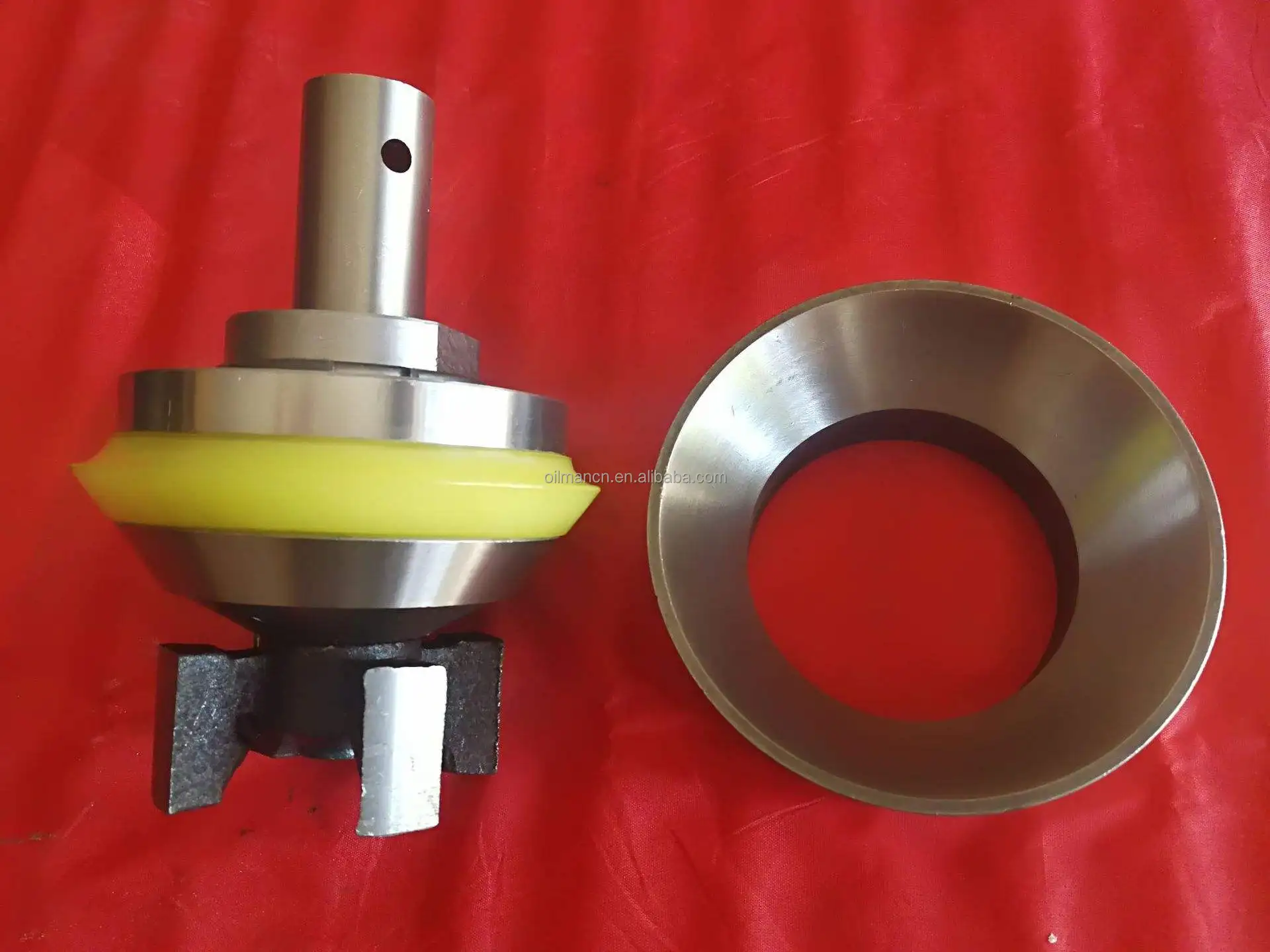
Mud Pump Valve & Seat are made of premium alloy steel through one-piece forging and carburizing treatment processes, thereby ensuring high intensity. In addition, the precise calculation is performed and CNC machining is conducted for the dimensional matching of the valve seat and valve body working angles to enhance the service life of the valve body and valve seat. Our valve products are able to work smoothly in normal mining and digging conditions for over 400 hours.

Mystique Mud pump Coolant and Lubricant extends mud pump liner and piston life and provides internal lubrication and extra cooling to the coolant system of mud pumps. It extends the life of all liners, even ceramic. Mystique will not cause corrosion or rusting of iron, and is safe with all alloys. Recommened dilution rate of 12.5%. (25 gallons will treat a 200-gallon system.) For use on closed systems.
The invention relates generally to valves suitable for abrasive fluids under high pressures. More specifically, the invention relates to valve bodies having at least one integral seal retention groove.
A valve suitable for abrasive fluids such as oil field drilling mud comprises a valve body and a corresponding valve seat, with certain valve bodies incorporating an elastomeric seal within a peripheral seal retention groove. Such a valve is usually mounted in the fluid end of a pump incorporating positive displacement pistons or plungers in multiple cylinders. Such valves may be stem-guided full-open designs (i.e., having a top guide stem and a bottom crow-foot guide on the valve body) or web-seat, stem-guided designs (i.e., having top and bottom guide stems on the valve body). Note that stem-guided full-open designs are also commonly known as full-open seat wing-guided designs; the former term will be used herein for convenience. However named, the above valves are expensive to manufacture, especially the moving portion or valve body. Besides requiring finish machining to close tolerances for adequate sealing, such valve bodies must be made strong enough to resist significant distortion under load with resultant leaks and fatigue failures. Prior efforts to reduce distortion under load by strengthening such valve bodies have generally resulted in higher cost and/or heavier designs which exacerbate sealing problems and/or increase the stress of impact loading on components of the valve assembly.
Commercially important design improvements necessarily reflect the fact that certain mud pump valve body and seat dimensions are effectively limited by industry practices and American Petroleum Institute (API) Standards. For example, the web-seat, stem-guided designs favored for mud pump valves are commonly made compatible with the industry benchmark widely known as the TRW Mission 4-web seat, which determines many valve dimensions. Further, API Standards determine the envelope into which valve bodies and seats must f


 8613371530291