
mud pump valve seat failure quotation
Alibaba.com offers pump valve, and a variety of different sizes to meet the needs of different customers. If it iss to the type of mud pump seat, it is possible to choose from a set of mud pump seals with alternate patterns, designs, and colors. On the other hand, the pivoted seat is the enduro, and the enduro has a wide range of sizes. If inflated mud pumps are not classified by one type or the other as a part of the body, it is important to consider the size of the seat and will be based on the type of mud pump seat. For a set of the two or less sizes, it is important to find the right type of mud pump seals on Alibaba.com, or known as " mud" seal, and all come in a variety of colors, and designs. Among the most popular mud pump valve seat choices are available based on the type of mud pump.@@@@@
There are also semi-trush mud pump seats, including electric pump seats, and semi-trush mud pump seats so that airflow can be found on the surface. There are many choices of mud pump seats, including electric pump seats, and semi-trash mud pump seats.

The fluid end of a duplex or triplex pump offers hundreds of opportunities for error. The results of an error in such a high-pressure system can mean (1) expensive downtime on the pump and maybe the entire rig, (2) expensive repair-replacement, and (3) possible injury or death of a crewman or a company man. Under the laws of nature, pump pistons and liners will wear, and there will be some corrosion and metallurgical imperfections, but the majority of pump failures are manmade. Theoretically, thorough training and retraining should avoid most mud pump problems. Realistically, a critical failure analysis during repair will be necessary to determine how to correct the failure. Telltale signs of trouble are distortion of piston rods, frayed piston polymer, discoloration, odor, hard-to-remove piston, rod cracks, pitting, total fracture, valve seat wear, and unsuitable external appearance.

Mud Pump Valve & Seat are made of premium alloy steel through one-piece forging and carburizing treatment processes, thereby ensuring high intensity. In addition, the precise calculation is performed and CNC machining is conducted for the dimensional matching of the valve seat and valve body working angles to enhance the service life of the valve body and valve seat. Our valve products are able to work smoothly in normal mining and digging conditions for over 400 hours.

Customers said they wanted long-lasting, easy-to-use valves and seats, and we delivered. Made from domestically sourced steel, GD Energy Products valves feature a two-piece friction-welded design, proprietary bonded inserts, and innovative geometry to deliver significantly longer life. GD Energy Products’ field proven Valves & Seats meet API Standard, and come with our “Ready Inventory” promise that we’ll have it in stock, when you need it.
Our full-open valves and seats are designed for use in GD Energy Products PZ, F-Series, and National 12P lines of triplex drilling pumps. This gives you options to use these parts across your whole fleet of pumps.

The present invention relates generally to valves used in pumps handling abrasive fluids. More specifically, the present invention provides an improved valve seat which significantly reduces the impact stress on valves and seat assemblies during the pumping operation, resulting in reduced wear on the valve assembly and improved reliability for the pumping system.
Pumping systems which are used to pump drilling mud and other abrasive fluids generally incorporate positive displacement pistons or plungers which operate in a reciprocating manner in individual cylinders. Each piston or plunger cylinder has a suction and discharge valve and valve seat operating alternatingly and independently to control flow into and out of each cylinder. The valve typically comprises a disc-shaped body portion which includes an elastomeric valve insert which serves to seal the valve when in the closed position and also serves to cushion the impact of the valve body in the valve seat. A lower conical seating surface of the valve body also makes contact with the valve seat when the valve is in the closed position.
Because of high pump pressures (between 2000 and 5000 psi) and the abrasive solid particles suspended in the drilling mud, valves and valve seats wear at a rapid rate and must be replaced frequently. One of the most significant points of impact stress in the valve assembly is the point of contact of the lower conical portion of the valve body and the valve seat when the valve is in the closed position. The extremely high differential pressures in the valve cause the conical portion of the valve body to engage the valve seat with a very high impact. The repetitive impact eventually causes the faces of the valve body and the valve seat to become worn and pitted. There is a need for an improved valve seat which reduces the impact stress related to the impact of the valve body with the valve seat.
The apparatus of the present invention overcomes the difficulties of the prior art by providing an improved valve seat which significantly decreases the impact stress caused by the impact of a mud pump valve body against the valve seat. The valve seat comprises a generally cylindrical body portion with a sealing surface which is sloped from the outer surface of the cylindrical body portion toward an interior throat of said cylindrical body portion. The valve body comprises a generally disc-shaped portion and a truncated contical portion. An elastomer insert is received in a groove in the valve body. The conical portion of the valve comprises a sloped face, including a metal portion and an elastomeric portion formed by the elastomeric insert. In the valve seat of the present invention, an annular pressure relief groove in the cylindrical body portion of the valve seat allows the sloped face of the valve seat to flex thereby relieving a significant amount of the impact load between the opposing faces of the valve assembly.
FIG. 2a is a cross-sectional view of the valve assembly of FIG. 1, showing the valve received in the valve seat with the valve in the closed position, just prior to maximum impact of the valve body against the valve seat.
FIG. 2b is cross-sectional view of the valve assembly of FIG. 1, showing the valve received in the valve seat with the valve in the closed position just after maximum impact of the valve body against the valve seat.
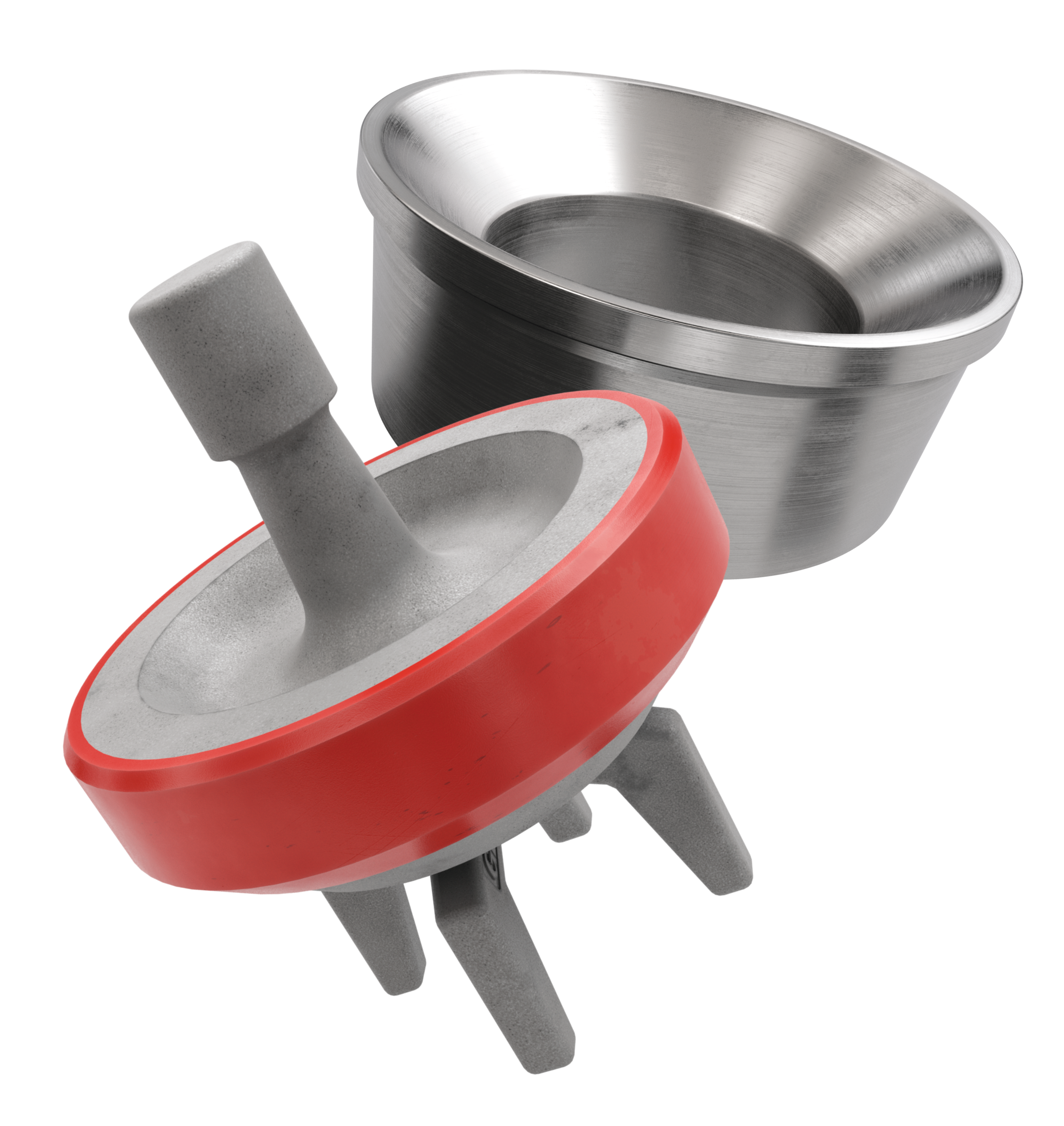
FIG. 1 is a perspective view of a mud pump valve assembly 10 comprising the improved valve seat of the present invention. The valve assembly shown in FIG. 1 is in the full open position. The valve assembly 10 is broadly comprised of a valve body 12 and a valve seat 14. The valve body comprises an upper valve guide 16 which maintains proper registration of the valve body within the pump housing. A plurality of valve guide feet 18 serve to maintain proper alignment of the valve with respect to the valve seat 14. The valve body comprises a generally disc-shaped portion 20 which is formed of metal, such as steel which has been heat treated by a carburizing process. The outer portion of the disc-shaped body has a generally C-shaped cross-section with an annular groove being defined by the interior of the C-shaped portion. A polyurethane or rubber insert is received in this groove. The insert serves to provide a partial damping of the impact of the valve body against the valve seat. However, this impact in most prior art systems is still high enough to cause significant wear on the operating faces of the valve body and the valve seat.
The lower portion of the valve body has a somewhat conical cross-section with a sloped surface illustrated by reference numeral 24. The sloped surface 24 comprises a rubber portion illustrated by reference numeral 26 and a metal portion illustrated by reference numeral 28. The valve seat 14 comprises a seating surface 30 with a portion 32 which engages the rubber portion 26 of the valve body surface and a portion 34 which engages the metal portion 28 of the valve body surface. FIG. 2a is a cross-sectional view of the valve assembly of FIG. 1, showing the valve received in the valve seat with the valve in the closed position, just prior to maximum impact of the valve body against the valve seat. FIG. 2b shows the valve received in the valve seat with the valve in the full closed position, with maximum impact of the valve body against the valve seat. Typically, the elastomer portion of the valve seating surface will make initial contact with the seating face of the valve seat. This is illustrated in FIG. 2a by the contact of the sloped face 26 of the elastomer insert 22 against the portion 32 of the sloped metal face of the valve seat. Note that the metal portion 28 of the sloped face of the valve body is not yet in contact with the portion 34 of the sloped face of the valve seat. The extremely high differential pressure on opposite sides of the valve, however, causes the elastomer insert 22 to compress rapidly to the position illustrated by the compressed elastomer insert 22 shown in FIG. 2b. The rapid compression of the elastomer insert results in an extremely high impact of the metal portion 28 of the valve face with the portion 34 of the valve seat face. In prior art valve seats this results in rapid wear of the metal portion 28 of the valve body and the portion 34 of the valve seat face. In the valve seat of the present invention, however, an annular pressure relief groove 36 allows the sloped face of the valve seat to flex thereby relieving a significant amount of the impact load between the opposing faces of the valve assembly.
Details relating to the valve seat 14 can be seen by referring to the cross-sectional illustration of FIG. 3. The outer surface of the valve seat comprises a valve seat shoulder 38 and a sidewall 40 having a conical taper. The slope of the sidewall 40 allows the valve seat to be received in a standard pump deck portion of a valve pot. The valve seat throat 42, defined by the internal cylindrical sidewall 44, transports the fluid passed through the valve assembly.
FIG. 4 is an enlarged view of a portion of the valve seat of the present invention showing details relating to the annular pressure relief groove 36. The relief groove is defined by vertical sidewalls 46 and 48 and an arch connecting the upper portions of the sidewalls 46 and 48. The arch is defined by two 90 degree segments with the inside segment having a radius which is two times as large as the radius of the outside 90 degree segment. The tangent point, illustrated by the reference numeral 50 is a point of smooth transition between the radii of the inside and the outside radii of the arch. The inside portion of the arch having the increased radius corresponds to the portion of the valve seat face which bears the impact of the metal portion of the valve body. Thus the impact load transmitted from the seating surface is dispersed over the larger radius inside the relief groove. This configuration maximizes flexure of the seating surface while preventing a stress concentration that would result in catastrophic shear failure of the seat.
Wear in the seating surface is directly proportional to the impact stress on the seating surface area of the valve seat. Impact stress "σ," which is reduced by the increased flexibility of the design of the present invention, is calculated using the following formula:
Utilizing finite element stress analysis, the calculated values for σs are approximately equal for the seating surface of a seat designed by the prior art and for the seating surface of the present invention. For both designs, the value of "h" is fixed and equal, being determined by the valve body and insert design. Again by finite element calculations, "y," deflection, is increased by a factor of 2 for the present invention. Using these values, the above equation yields values for impact stress, "σ," that are reduced by approximately 30% by the present invention.
The elastomeric insert is also positively affected by the present invention. The elastomeric seal, which is usually made of rubber or polyurethane material does not wear in the manner that the metal valve body and valve seat wear, i.e., through material loss. Material loss of the elastomeric seal is small during normal pump operation. Instead, the constant cyclical compression of the seal results in hysterisis in the seal that results in internal heat buildup and the eventual degradation of material strength to the point that the seal fails. As the metal valve and seat wear in the form of material loss from the impact stress, the amount of compression increases, hysterisis also increases to the point that material strength loss in the seal is accelerated and seal failure occurs after a shorter number of total cycles. Therefore, reduction in the wear rates of the metal valve body and valve seat also increases the life of the valve seal.
The flexible seat design of the present invention also improves pump operation because the valve opens faster and allows the pumped fluid to enter or leave the cylinder quicker. Because of the increased seat deflection, the seat stores energy that can be used to accelerate the valve to the open position before the piston or plunger begins the next stroke. In other words, the increased seat deflection acts like a recoiled spring which results in faster valve opening for smoother and more efficient pump operation.

(1) The diesel engine speed of the main pump station is too low, the fuel supply is insufficient, and the supply pressure of the hydraulic system is too low;
(2) The hydraulic system of the mud pump supplied by the main pumping station is faulty or the pressure adjustment of the overflow valve in the system is low and the internal leakage is serious, and the supply pressure is insufficient;
(1) Increase the speed of the diesel engine at the main pump station (n is greater than or equal to 1500 r/min), increase the fuel supply of the motor, and increase the effective working pressure of the hydraulic system (above 10MPa);
(2) Solution: Replace the O-ring of the cylinder head or valve cover, pay attention to adding butter before installing, to prevent the O-ring from cutting edges.
(1) Cause analysis: the steel ball or valve hole on the safety valve is damaged; the steel ball and valve seat on the safety valve are rusted; sand particles are accumulated around the ball valve on the safety valve, and the slurry is agglomerated.
(2) Solution: replace the steel ball or valve seat; remove the rust on the steel ball and valve seat; remove and clean the sundries of the safety ball valve.
(1) Reason analysis: The diesel engine speed of the main pumping station is low and the fuel supply is insufficient, resulting in insufficient flow of the water pump and the pressure cannot rise.
(2) Solution: Increase the diesel engine speed of the main pump station (n is greater than or equal to 1500 r/min), increase the motor oil supply, increase the water pump flow, and then increase the pressure; unscrew the pressure gauge and fill the buffer with oil or After replacing the rubber diaphragm, fill it with engine oil.
The reasons and solutions for the failures that often occur in mud pump operations are listed above. The equipment failures caused by specific reasons in the use of mud pumps are different. Reasonable use and maintenance of the equipment can extend the service life of the equipment.

Mud pump valve seats are used in on-shore and offshore oil and gas drilling operations and in pumps used in land-based fracking operations. Valves used in these types of pumping equipment operate at a very high frequency – up to one hertz (one cycle per second) – and are prone to high wear and degradation from hysteresis. Parker’s premium grade valve seats feature our Resilon® Polyurethane which has a high modulus of elasticity to successfully withstand high frequency operation and resist hysteresis.
Where typical urethane valves may last up to 400 hours, our proven valve seat designs with Resilon Polyurethane have lasted up to 800 hours (400 hours longer) – greatly improving drilling productivity through longer life. Longer valve seat life means maintenance intervals can be extended and production jobs can be completed before service is required.

Also known as Nova Tech Valve or Roughneck Valve or High Pressure Valve. Full open Seat & wing guided Valve design features a large metal-to-metal bearing area for long life, directly casted urethane insert on valve body results in a perfect round shape that prevents premature failures of the insert. The insert is casted around the serrations, thus failure due to tears from the serrations are eliminated Most importantly the insert is not stretched over the valve during installation; there are no residual stresses left, to shorten insert life.

The frac pump valves and seats are also called valve and seat assembly. There are valve body, valve insert, valve seat, and O-ring, these four parts consist of the frac pump valves and seats, which are very critical vulnerable parts in fracturing pumps. In higher pressure frac pumps, the mating surface of the valve body and valve seat is generally a conical surface. Frac valves and seats are the no. 1 expendables cost. 8620H or 20CrMo can be used for forged frac valves and seats. Both the valve body and valve seat would be carburized or nitrided to enhance their impact resistance and wear resistance. Polyurethane is often used as the raw material for the valve insert. Compared with rubber, polyurethane has better strength and elasticity.
This FAQ lists some questions about frac pump valves and seats for you. These FAQs shall be able to answer some queries related to the well-service pump valves and seats.
Four-web Valve: It is also called Supreme Type Valve: It is a stem-guided four web seat valve. The crossed structure valve seat assembly maximizes the service life, as it improves the impact absorption due to flapping the valve body.
Full Open Valve: It is a four-wing guided full open frac valves and seats. The full open design expands the flow area and provides excellent flow traits. It is easier to maintain, assemble and handle lost circulation material better than most conventional style valve seats assembly. There are four types of full pen valves that are popularly used in oilfields:
Novatech is a valves and seats manufacturer in the US. Its first welding valves were supplied nationally in 1982. As one of the oldest and strongest frac valves and seat manufacturers, a wide variety of valves & seats manufactured by Novatech are used throughout the world.
Novatech’s four streamlined guide legs full open seat valve have greatly increased the reliability and performance. The web-type valve seat was achieved to maximize the metal-to-metal bearing area. However, the loads applied to the seat webs are not uniform, the flow is not limited because of the Novatech four streamlined guide legs and the metal-to-metal bearing area is regained, the Novatech full open valve seat assembly can keep the impact loads uniformly transmitted to the frac pump fluid end. One-piece valve bodies, the insert retention groove acts as a circular channel beam to add superior rigidity to the valve body.
TianyuMfg provides 100% interchangeable frac valves and seats with Novatech’s. Our valves and seats are manufactured by high-quality alloy steel and which is forged integrally. The developed high, medium, and low-end products suit different working conditions for you to choose, including work-over, acidizing, cementing, fracturing, and drilling.
The plungers size defines the frac pump fluid end size. The frac pump valves and seats change with the plunger size but not all the same, some fluid ends of different plunger specs also share the valves and seats of the same size. You can find the following charts which list the general sizes of frac pump valves and seats:
Tianyu Mfg. Provides various kinds of frac pump valves and seats. Contact TianyuMfg sales engineer to get the most appropriate valves and seats for your pumps.
The frac pump valve section is divided into the suction valve and discharge valve on the drawings. However, in order to make the disassemble and maintenance of the frac pump valve convenient, the suction and the discharge valve body adopt the exactly same design. The suction valve body is located at the lower part of the frac pump fluid end, and the discharge valve is located at the upper part of the frac pump fluid end.
When you are inquiry about the suction or discharge frac valves and seats, Tianyu Mfg. provides the same design frac valves and seats, same as Weir SPM.
By the reciprocating movement of the plunger, the suction valve and the discharge valve continuously open and close. When the suction valve keeps opening and the discharge valve closing, the liquid pours into the frac pump fluid end cylinder cavity through the suction manifold and the suction valve to complete the liquid suction. When the discharge valve keeps opening and the suction valve closing, the liquid discharge from the frac pump fluid end cylinder cavity through the discharge valve land the discharge pipe to complete the liquid discharge.
In the operation of the frac pump, the frac pump valves and seats are constantly opening and closing. Therefore, the closing speed of the frac pump valves and seats require special attention. There is a certain impact that emerges due to kinetic energy changing at the closing moment of the frac pump valves. The impact strength is related to the mass and closing speed of the frac pump valves and seats. The greater the mass and speed are, the greater the impact strength will be. The shock is the main factor that triggers the frac pump valves and seats to be damaged. It makes the allowable closing speed is a key parameter of the frac pump valves and seats design.
You need to prepare sufficient spare frac pump valves and seats parts. The quality of frac pump valves and seats directly affect the performance of the frac pump fluid end. Tianyu Mfg. serves low cost and superior performance frac pump valves and seats. As the valve body is manufactured as a one-piece, which increased resistance to abrasion and extrusion, also minimizes insert movement, leakage, and separation from the valve.
For frac valve assembly, when the insert wear has nibbling but not bridged across the surface, the valve has even worn but no chips or washouts and function is still good, keep them working.
When the insert is almost damaged across the surface and caused the valve to leak, replace the insert. After replacing, no leakage keeps them working. Leakage till happened, replace the frac pump valve body. The leakage caused by the insert failure would arise the valve washout and fail easily tend to rapid erosion.
Increasing the metal-to-metal bearing area between the valve and seat is the only method to lengthen the life span of the frac pump valves and seats. The bigger this area, the bigger the area to absorb the high-impact energy from valve closing. We recommend the following tips for you as a reference.
The frac valves seats assembly should be opened and closed in time. The closing speed and hysteresis angle must be less than the allowable value. In this way, the shock strength emerges in the open and closing would be reduced.


 8613371530291