
scr mud pump free sample

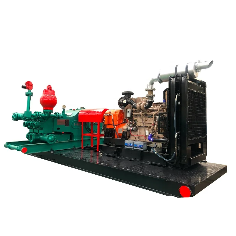
The 2,200-hp mud pump for offshore applications is a single-acting reciprocating triplex mud pump designed for high fluid flow rates, even at low operating speeds, and with a long stroke design. These features reduce the number of load reversals in critical components and increase the life of fluid end parts.
The pump’s critical components are strategically placed to make maintenance and inspection far easier and safer. The two-piece, quick-release piston rod lets you remove the piston without disturbing the liner, minimizing downtime when you’re replacing fluid parts.
The SCR Drive Assignment Contactors are fitted in the armature and are actuated by Allen Bradley PLC logic; through Allen Bradley flex I/O located in the SCR drive bay. The flex I/O communicates through a dual loop Profibus configuration to a processor for the first five SCR bays and a second matching configures for the next five SCR bays. The assignment configuration is such that any motor is assignable in three locations with any motor capable of assigning to the first five SCR bay or the second set of five SCR bays.
Each drive can support 4 different motor parameter sets. All the SCR Drives on the Frontier Driller shall be configured accordingly to the motors that they will support.
This architecture offers flexibility and reliability through redundancy in case of SCR drive failure. Should such an event occur the operator simply turns off the motor on the faulted SCR drive and turns back on allowing the PLC to assign to the next available SCR drive. Each motor is assignable to three different SCR drives with a total of twenty (20) SCR drives in the system.
The SCR Drives are controlled from consoles via profibus loop circuit to the dual redundant Logix 5561 CPU Allen Bradley PLC system. Overview of the SCR distribution with SCR PLC.
By use of the dual 5561 Allen Bradley processor (CPU) in the PLC system either processor can fail with no loss of operation. Communications to the drives is done by Profibus loop directly to the Siemens 6RA70 and flex I/0 locate each SCR bay. The flex I/O receives input and from devices outside the drive such as armature contactor feedback, drive cooling fan overload, circuit breaker status and the OFF/DRILL/MARINE selector switch. The flex I/0 receives output commands outside of the 6RA70 control for contactor assignments. The Siemens 6RA70 SCR drive sends and receives data as per the supplied manual, which controls operation of the motor and gathers operating information for logic control. All control signals from SCR to PLC shall be communicated through PROFIBUS DP field bus protocol, with the exception of the Emergency Stops, which shall be hardwired directly to the SCR Drive breaker for safety.
Signals exchanged between an SCR and its respective PLC are the same for each SCR. Apart from standard control/status signals, signals related to assignment and power management need to be exchanged.
There is a PROFIBUS DP communication network for each SCR drive to the two PLC racks located in the generator cubicles. Each network is completely independent from the other with communications that are loop and able to be controlled by either CPU. The PLC racks located in the Driller’s Console and in the Mud Pump Console are networked by Ethernet Fiber optic loop to a MOXA module to convert the fiber signal. The two screens in the driller’s console are networked on this same loop with both screens able to display the same screens and status. There are two more MOXA modules connected in the same loop to supply data to the two workstations to enable data collection and trouble shooting of the complete system. There are two more MOXA modules on the same loop connected to PLC3A and PLC3B in the field supply cabinets, which in turn are connected to all the MCC, by Profibus fiber optic loop for control and status of all the required motor starters. Overview of the SCR PLC PROFIBUS DP and Ethernet communication network.
The PROFIBUS DP network in this application is based on 3 different mediums and topologies. A standard bus or line topology network with standard PROFIBUS DP RS-485 cable is established between an SCR PLC and its respective SCR drives. Each SCR is fitted with a CBP2 PROFIBUS communication board. Each one has its own address to differentiate between the various SCR Drives on the network. A redundant optical ring topology is established between all PLC racks via MOXA hub modules to form the Ethernet network. The third communication loop is Profibus fiber optic to all the Hirschmann Hub modules in the MCCs and the same type loop collecting data from the generator controls. MOXA modules and Hirschmann hub modules convert electrical signals to optical signals.
As of July 2007 we have completed the manufacturing portion of this project and have started testing the communications of the 5 remaining SCR Drive bays along with the Generator bays, Driller’s Console, Mud Pump Console & SCADA System. We have already shiped 5 DC drive bays and 1 of the 2 Isolation Switch bays and will ship the remaining equipment after completion of testing and DNV approvals.

The Zeefax Total Rig Auditavoids downtime and ensures rig systems remain operational and reliable. Many Drilling Companies will invest in a completeRig Auditin the knowledge that it offers a comprehensive overview of the state of their rig, which can also be submitted for compliance and due diligence purposes.SCR Training Simulator
Every Drilling Rig must have a Power Control Room – sometimes also known as an SCR (standing for Silicon Controlled Rectifier) System – which forms the functional heart of the power control of the drilling operations. Typically, SCR systems comprise a large steel room, inside of which will be a range of Motor Control Centres, Engine & Generator Controls, SCR Control cubicles, and other instruments and systems used for drilling purposes.
SCR Systems usually operate at 600V, and clearly, these systems can be extremely dangerous if not operated correctly and carefully by suitably trained operators. It is therefore vital that drilling engineers and operators are well trained using a combination of class room tuition and on-the-job training.
In response to this need, Zeefax have created the world’s first full size SCR Training Simulator, which accurately mimics the a real SCR; it looks and feels like the real thing, providing a realistic experience of live field operations – but without the dangerous high voltage. This system was created specifically for Naftogaz – for more details, click here.
A key feature of the simulator is the addition of the on-board computer system, which mimics all of the signals that would normally come into this SCR system from the live engines and generators, including the motors running the mud pumps, the rotary table or the Drawworks, etc. and can also simulate a wide range of known faults, allowing trainees to experience first hand problem solving in the safety of the simulator, before they experience the live system.GE Legacy Drive Systems
Used the same type SCR bridge as the Generation III, but rated at only 1200-1500 amp since the heat sink assembly is of a slightly different design. This system uses the GE generator GEM modules controls.
1980’s, 900amp. SCR bridges using the GE GEM Generator Control. As the bridges are small it requires two SCR bays to run a two-motor Mud Pump or Drawworks.
If you are interested in applying for this position, then please send us your latest CV and a covering letter toTest and Calibration Engineer – SCR products
Zeefax understands that replacement of a complete SCR Control System is often not viable due to the large cost and loss of production due to system downtime. At Zeefax we can offer a comprehensive service to support your legacy GE Drives and give it a renewed lease of life. That not only includes supply of spare parts and a repair/calibration service; qualified service engineers with years of experience with these Drives are available for regular Health Checks, fault-finding and general support purposes.Careers
Advancements in technology mean that many of the power semiconductors which were built into SCR systems 30 or more years ago have been superseded by new devices, often with improved specifications.
As part of our maintenance and service offerings for SCR systems, Zeefax is able to mobilise support and engineers to provide technical assistance during emergency shutdowns and downtime periods.
Given our years of experience and unique position to offer total support for all legacy Hill Graham Controls (HGC), and other manufacturer’s systems including Ross Hill Controls (RHC), IPS, and GE Micro Drill SCR systems, Zeefax can provide a full range of technical services for installation, commissioning, and ongoing operational support.SCR System Health Checks
The time to find out if your system is reliable is when operations are quiet – not during critical well operations – so the Zeefax SCR System Health Check is designed to identify potential weaknesses and either repair or replace immediately, or mitigate against these until a repair or replacement can be effected – usually at a quite time.
For reliable operation, the contact between the SCR devices and the heatsinks must be as good as possible but over time, and especially in offshore installations, corrosion may attack the interface between the SCR device plating and the aluminium heatsink. If corrosion is present it takes an expert to decide if refurbishment is required because as long as the damage is minimal and the two elements remain undisturbed, the mutual corrosion may still maintain a good contact.
In addition, we are able to repair and re-calibrate most Hill Graham and Ross Hill type printed circuit boards (PCBs), including Power Limit, Field Supply Regulator, Sprocket Slip, Drillers Console, DC Auxiliary, SCR Auxiliary and Generator Exciter PCBs. Furthermore if following evaluation, repair is not possible, in many cases we can supply new manufactured boards using the original designs, but enhanced by us using modern components and manufacturing techniques. In this way, we can help to ensure that legacy systems remain operational and continue to provide reliable and trouble free service beyond their expected life.Motors & Generators
Even given the relatively controlled working environment of typical SCR pods, the conditions can often cause deterioration to both electrical and mechanical performance, requiring removal of the unit from the system, followed by refurbishment and renovation.
The heat sinks are inspected and if required, will be re-machined to ensure excellent electrical contact is maintained. Importantly, the SCR Thyristor ‘puck’ is replaced, and very special attention is given to the clamping torque and orientation.
If you would like to know more about the range of available Driller’s Foot Throttles, please call or email us, and we will be pleased to assist.SCR Blower Assemblies
An important part of every system is the forced air cooling, which is vital to ensure continuity and reliability of operation of the SCR stacks. It is essential that the heat generated during operation is reliably carried away, and Zeefax now produce a series of SCR Blower Assemblies which are compatible with the those used in legacy Hill Graham and Ross Hill type systems.
The Zeefax SCR Blowers are designed to operate with voltages up to 600 V @ 50 or 60 Hz; the operating voltage needs to be specified at the time of purchase (see the details and specification form below) and the blower may be configured with either Single or Duplex impellers and with or without base frames.
In order to aid potential users with the selection of replacement blowers, we have created a simple form which can be used to provide the few technical details we require. In this way, we can ensure that any SCR Blower supplied by us is fully compatible with existing assemblies, and will then install directly into the available location with minimal re-work required. You can download this form from this site; please fill it in and return it to us to receive a quotation.
Prescription Safety Glasses Prescription safety glasses will be furnished by the employer. The employer retains the authority to establish reasonable rules and procedures regarding frequency of issue, replacement of damaged glasses, limits on reimbursement costs and coordination with the employer’s vision plan.
Switching and Tagging Rules The Developer and Connecting Transmission Owner shall each provide the other Party a copy of its switching and tagging rules that are applicable to the other Party’s activities. Such switching and tagging rules shall be developed on a nondiscriminatory basis. The Parties shall comply with applicable switching and tagging rules, as amended from time to time, in obtaining clearances for work or for switching operations on equipment.
I’ve run into several instances of insufficient suction stabilization on rigs where a “standpipe” is installed off the suction manifold. The thought behind this design was to create a gas-over-fluid column for the reciprocating pump and eliminate cavitation.
When the standpipe is installed on the suction manifold’s deadhead side, there’s little opportunity to get fluid into all the cylinders to prevent cavitation. Also, the reciprocating pump and charge pump are not isolated.
The suction stabilizer’s compressible feature is designed to absorb the negative energies and promote smooth fluid flow. As a result, pump isolation is achieved between the charge pump and the reciprocating pump.
The isolation eliminates pump chatter, and because the reciprocating pump’s negative energies never reach the charge pump, the pump’s expendable life is extended.
Investing in suction stabilizers will ensure your pumps operate consistently and efficiently. They can also prevent most challenges related to pressure surges or pulsations in the most difficult piping environments.
My first days as an MWD field tech I heard horror stories surrounding what is commonly referred to as “pump noise”. I quickly identified the importance of learning to properly identify this “noise”. From the way it was explained to me, this skill might prevent the company you work from losing a job with an exploration company, satisfy your supervisor or even allow you to become regarded as hero within your organization if you’ve proven yourself handy at this skill.
“Pump noise” is a reference to an instability in surface pressure created by the mud pumps on a modern drilling rig, often conflated with any pressure fluctuation at a similar frequency to pulses generated by a mud pulser, but caused by a source external to the mud pulser. This change in pressure is what stands in the way of the decoder properly understanding what the MWD tool is trying to communicate. For the better part of the first year of learning my role I wrongly assumed that all “noise” would be something audible to the human ear, but this is rarely the case.
A mud pulser is a valve that briefly inhibits flow of drilling fluid traveling through the drill string, creating a sharp rise and fall of pressure seen on surface, also known as a “pulse”.
Depending on if the drilling fluid is being circulated in closed or open loop, it will be drawn from a tank or a plastic lined reservoir by a series(or one) mud pumps and channeled into the stand pipe, which runs up the derrick to the Kelly-hose, through the saver sub and down the drill-pipe(drill-string). Through the filter screen past an agitator or exciter, around the MWD tool, through a mud motor and out of the nozzles in the bit. At this point the fluid begins it’s journey back to the drilling rig through the annulus, past the BOP then out of the flow line and either over the shale shakers and/or back in the fluid reservoir.
Developing a firm grasp on these fundamentals were instrumental in my success as a field technician and an effective troubleshooter. As you can tell, there are a lot of components involved in this conduit which a mud pulser telemeters through. The way in which many of these components interact with the drilling fluid can suddenly change in ways that slightly create sharp changes in pressure, often referred to as “noise”. This “noise” creates difficulty for the decoder by suddenly reducing or increasing pressure in a manner that the decoder interprets a pulse. To isolate these issues, you must first acknowledge potential of their existence. I will give few examples of some of these instances below:
Suction screens on intake hoses will occasionally be too large, fail or become unfastened thus allowing large debris in the mud system. Depending on the size of debris and a little bit of luck it can end up in an area that will inhibit flow, circumstantially resulting in a sudden fluctuation of pressure.
This specifically is a term used to refer to the mud motor stator rubber deterioration, tearing into small pieces and passing through the nozzles of the bit. Brief spikes in pressure as chunks of rubber pass through one or more nozzles of the bit can often be wrongly interpreted as pulses.
Sometimes when mud is displaced or a pump suction isn’t completely submerged, tiny air bubbles are introduced into the drilling fluid. Being that air compresses and fluid does not, pulses can be significantly diminished and sometimes non-existent.
As many of you know the downhole mud motor is what enables most drilling rigs to steer a well to a targeted location. The motor generates bit RPM by converting fluid velocity to rotor/bit RPM, otherwise known as hydraulic horsepower. Anything downhole that interacts with the bit will inevitably affect surface pressure. One of the most common is bit weight. As bit weight is increased, so does surface pressure. It’s important to note that consistent weight tends to be helpful to the decoder by increasing the amplitude of pulses, but inconsistent bit weight, depending on frequency of change, can negatively affect decoding. Bit bounce, bit bite and inconsistent weight transfer can all cause pressure oscillation resulting in poor decoding. Improper bit speed or bit type relative to a given formation are other examples of possible culprits as well.
Over time mud pump components wear to the point failure. Pump pistons(swabs), liners, valves and valve seats are all necessary components for generating stable pressure. These are the moving parts on the fluid side of the pump and the most frequent point of failure. Another possible culprit but less common is an inadequately charged pulsation dampener. Deteriorating rubber hoses anywhere in the fluid path, from the mud pump to the saver sub, such as a kelly-hose, can cause an occasional pressure oscillation.
If I could change one thing about today’s directional drilling industry, it would be eliminating the term “pump noise”. The misleading term alone has caused confusion for countless people working on a drilling rig. On the other hand, I’m happy to have learned these lessons the hard way because they seem engrained into my memory. As technology improves, so does the opportunities for MWD technology companies to provide useful solutions. Solutions to aid MWD service providers to properly isolate or overcome the challenges that lead to decoding issues. As an industry we have come a lot further from when I had started, but there is much left to be desired. I’m happy I can use my experiences by contributing to an organization capable of acknowledging and overcoming these obstacles through the development of new technology.


 8613371530291