
what is a swab on a mud pump in stock

If you run a mud rig, you have probably figured out that the mud pump is the heart of the rig. Without it, drilling stops. Keeping your pump in good shape is key to productivity. There are some tricks I have learned over the years to keeping a pump running well.
First, you need a baseline to know how well your pump is doing. When it’s freshly rebuilt, it will be at the top efficiency. An easy way to establish this efficiency is to pump through an orifice at a known rate with a known fluid. When I rig up, I hook my water truck to my pump and pump through my mixing hopper at idle. My hopper has a ½-inch nozzle in it, so at idle I see about 80 psi on the pump when it’s fresh. Since I’m pumping clear water at a known rate, I do this on every job.
As time goes on and I drill more hole, and the pump wears, I start seeing a decrease in my initial pressure — 75, then 70, then 65, etc. This tells me I better order parts. Funny thing is, I don’t usually notice it when drilling. After all, I am running it a lot faster, and it’s hard to tell the difference in a few gallons a minute until it really goes south. This method has saved me quite a bit on parts over the years. When the swabs wear they start to leak. This bypass pushes mud around the swab, against the liners, greatly accelerating wear. By changing the swab at the first sign of bypass, I am able to get at least three sets of swabs before I have to change liners. This saves money.
Before I figured this out, I would sometimes have to run swabs to complete failure. (I was just a hand then, so it wasn’t my rig.) When I tore the pump down to put in swabs, lo-and-behold, the liners were cut so badly that they had to be changed too. That is false economy. Clean mud helps too. A desander will pay for itself in pump parts quicker than you think, and make a better hole to boot. Pump rods and packing last longer if they are washed and lubricated. In the oilfield, we use a petroleum-based lube, but that it not a good idea in the water well business. I generally use water and dish soap. Sometimes it tends to foam too much, so I add a few tablets of an over the counter, anti-gas product, like Di-Gel or Gas-Ex, to cut the foaming.
Maintenance on the gear end of your pump is important, too. Maintenance is WAY cheaper than repair. The first, and most important, thing is clean oil. On a duplex pump, there is a packing gland called an oil-stop on the gear end of the rod. This is often overlooked because the pump pumps just as well with a bad oil-stop. But as soon as the fluid end packing starts leaking, it pumps mud and abrasive sand into the gear end. This is a recipe for disaster. Eventually, all gear ends start knocking. The driller should notice this, and start planning. A lot of times, a driller will change the oil and go to a higher viscosity oil, thinking this will help cushion the knock. Wrong. Most smaller duplex pumps are splash lubricated. Thicker oil does not splash as well, and actually starves the bearings of lubrication and accelerates wear. I use 85W90 in my pumps. A thicker 90W140 weight wears them out a lot quicker. You can improve the “climbing” ability of the oil with an additive, like Lucas, if you want. That seems to help.
Outside the pump, but still an important part of the system, is the pop-off, or pressure relief valve. When you plug the bit, or your brother-in-law closes the discharge valve on a running pump, something has to give. Without a good, tested pop-off, the part that fails will be hard to fix, expensive and probably hurt somebody. Pop-off valve are easily overlooked. If you pump cement through your rig pump, it should be a standard part of the cleanup procedure. Remove the shear pin and wash through the valve. In the old days, these valves were made to use a common nail as the shear pin, but now nails come in so many grades that they are no longer a reliable tool. Rated shear pins are available for this. In no case should you ever run an Allen wrench! They are hardened steel and will hurt somebody or destroy your pump.
One last thing that helps pump maintenance is a good pulsation dampener. It should be close to the pump discharge, properly sized and drained after every job. Bet you never thought of that one. If your pump discharge goes straight to the standpipe, when you finish the job your standpipe is still full of fluid. Eventually the pulsation dampener will water-log and become useless. This is hard on the gear end of the pump. Open a valve that drains it at the end of every job. It’ll make your pump run smoother and longer.

As usual, winter — or the slow season — is the time most drillers take the time to maintain their equipment in order to get ready for the peak season. One of the main parts that usually needs attention is the mud pump. Sometimes, it is just a set of swabs to bring it up to snuff, but often, tearing it down and inspecting the parts may reveal that other things need attention. For instance, liners. I can usually run three sets of swabs before it is time to change the liner. New liners and swabs last a good long time. The second set of swabs lasts less, and by the time you put in your third set of swabs, it’s time to order new liners. Probably rods too. It’s not always necessary to change pistons when you change swabs. Sometimes just the rubber needs to be changed, saving money. How do you tell? There is a small groove around the outside of the piston. As it wears, the groove will disappear and it’s time for a new piston.
The wear groove on a piston can be a good indicator of the general health of your pump. If the wear is pretty even all around, chances are the pump is in pretty good shape. But if you see wear on one side only, that is a clue to dig deeper. Uneven wear is a sign that the rods are not stroking at the exact angle that they were designed to, which is parallel to the liner. So, it’s time to look at the gear end. Or as some folks call it, “the expensive end.”
The wear groove on a piston can be a good indicator of the general health of your pump. If the wear is pretty even all around, chances are the pump is in pretty good shape. But if you see wear on one side only, that is a clue to dig deeper.
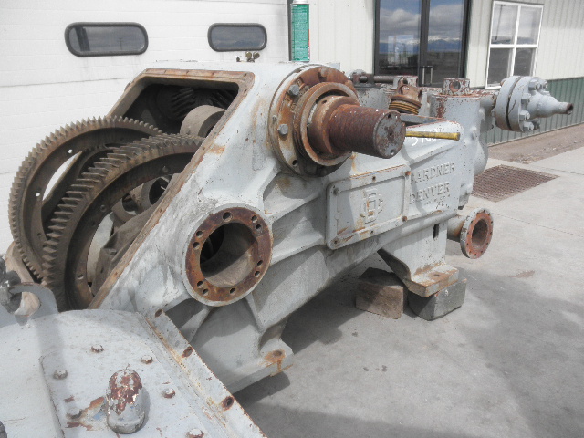
After you get the cover off the gear end, the first thing to look at will be the oil. It needs to be fairly clean, with no drill mud in it. Also look for metal. Some brass is to be expected, but if you put a magnet in the oil and come back later and it has more than a little metal on it, it gets more serious. The brass in the big end of the connecting rod is a wearable part. It is made to be replaced at intervals — usually years. The most common source of metal is from the bull and pinion gears. They transmit the power to the mud. If you look at the pinion gear closely, you will find that it wears faster than the bull gear. This is for two reasons. First, it is at the top of the pump and may not receive adequate lubrication. The second reason is wear. All the teeth on both the bull and pinion gears receive the same amount of wear, but the bull gear has many more teeth to spread the wear. That is why, with a well maintained pump, the bull gear will outlast the pinion gear three, four or even five times. Pinion gears aren’t too expensive and are fairly easy to change.
If the gears look OK and there are no obvious bearing problems, the next parts to look at are the crank journals; they ride in the brass at the big end of the rod and take plenty of abuse. This is where it gets interesting. To repair or replace is the big question. Replacement is pretty expensive and you may have to wait a while. Repairs are more my style because I know some excellent machinists and can tell them exactly what I need done. If your journals are deeply scored, you will have to turn the crank. It takes a pretty special machine to do this, but one of my friends has one and is a master with it. The procedure is to turn down the journals and press a steel sleeve over them, bringing them up to factory new specs.
This process is fairly straightforward machine work, but over the years, I have discovered a trick that will bring a rebuild up to “better than new.” When you tear a pump down, did you ever notice that there is about 1-inch of liner on each end that has no wear? This is because the swab never gets to it. If it has wear closer to one end than the other, your rods are out of adjustment. The trick is to offset grind the journals. I usually offset mine about ¼-inch. This gives me a ½-inch increase in the stroke without weakening the gear end. This turns a 5x6 pump into a 5½x6 pump. More fluid equals better holes. I adjust the rods to the right length to keep from running out the end of the liner, and enjoy the benefits.
Other than age, the problem I have seen with journal wear is improper lubrication. Smaller pumps rely on splash lubrication. This means that as the crank strokes, the rods pick up oil and it lubricates the crank journals. If your gear end is full of drill mud due to bad packing, it’s going to eat your pump. If the oil is clean, but still shows crank wear, you need to look at the oil you are using.
Oil that is too thick will not be very well picked up and won’t find its way into the oil holes in the brass to lubricate the journals. I’ve seen drillers that, when their pump starts knocking, they switch to a heavier weight oil. This actually makes the problem worse. In my experience, factory specified gear end oil is designed for warmer climates. As you move north, it needs to be lighter to do its job. Several drillers I know in the Northern Tier and Canada run 30 weight in their pumps. In Georgia, I run 40W90. Seems to work well.

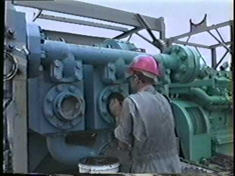
Mud pump is one of the most critical equipment on the rig; therefore personnel on the rig must have good understanding about it. We’ve tried to find the good training about it but it is very difficult to find until we’ve seen this VDO training and it is a fantastic VDO training about the basic of mud pumps used in the oilfield. Total length of this VDO is about thirteen minutes and it is worth to watch it. You will learn about it so quickly. Additionally, we also add the full detailed transcripts which will acceleate the learning curve of learners.
Powerful mud pumps pick up mud from the suction tank and circulate the mud down hole, out the bit and back to the surface. Although rigs usually have two mud pumps and sometimes three or four, normally they use only one at a time. The others are mainly used as backup just in case one fails. Sometimes however the rig crew may compound the pumps, that is, they may use three or four pumps at the same time to move large volumes of mud when required.
Rigs use one of two types of mud pumps, Triplex pumps or Duplex pumps. Triplex pumps have three pistons that move back-and-forth in liners. Duplex pumps have two pistons move back and forth in liners.
Triplex pumps have many advantages they weight 30% less than a duplex of equal horsepower or kilowatts. The lighter weight parts are easier to handle and therefore easier to maintain. The other advantages include;
• One of the more important advantages of triplex over duplex pumps, is that they can move large volumes of mud at the higher pressure is required for modern deep hole drilling.
Triplex pumps are gradually phasing out duplex units. In a triplex pump, the pistons discharge mud only when they move forward in the liner. Then, when they moved back they draw in mud on the same side of the piston. Because of this, they are also called “single acting.” Single acting triplex pumps, pump mud at a relatively high speeds. Input horsepower ranges from 220 to 2200 or 164 to 1641 kW. Large pumps can pump over 1100 gallons per minute, over 4000 L per minute. Some big pumps have a maximum rated pressure of over 7000 psi over 50,000 kPa with 5 inch/127 mm liners.
Here is a schematic of a triplex pump. It has three pistons each moving in its own liner. It also has three intake valves and three discharge valves. It also has a pulsation dampener in the discharge line.
Look at the piston at left, it has just completed pushing mud out of the liner through the open discharge valve. The piston is at its maximum point of forward travel. The other two pistons are at other positions in their travel and are also pumping mud. But for now, concentrate on the left one to understand how the pump works. The left piston has completed its backstroke drawing in mud through the open intake valve. As the piston moved back it instead of the intake valve off its seat and drew mud in. A strong spring holds the discharge above closed. The left piston has moved forward pushing mud through the now open discharge valve. A strong spring holds the intake valve closed. They left piston has completed its forward stroke they form the length of the liner completely discharging the mud from it. All three pistons work together to keep a continuous flow of mud coming into and out of the pump.
Crewmembers can change the liners and pistons. Not only can they replace worn out ones, they can also install different sizes. Generally they use large liners and pistons when the pump needs to move large volumes of mud at relatively low pressure. They use a small liners and pistons when the pump needs to move smaller volumes of mud at a relatively high pressure.
In a duplex pump, pistons discharge mud on one side of the piston and at the same time, take in mud on the other side. Notice the top piston and the liner. As the piston moves forward, it discharges mud on one side as it draws in mud on the other then as it moves back, it discharges mud on the other side and draws in mud on the side it at had earlier discharge it. Duplex pumps are therefore double acting.
Double acting pumps move more mud on a single stroke than a triplex. However, because of they are double acting they have a seal around the piston rod. This seal keeps them from moving as fast as a triplex. Input horsepower ranges from 190 to 1790 hp or from 142 to 1335 kW. The largest pumps maximum rated working pressure is about 5000 psi, almost 35,000 kPa with 6 inch/152 mm linings.
A mud pump has a fluid end, our end and intake and the discharge valves. The fluid end of the pump contains the pistons with liners which take in or discharge the fluid or mud. The pump pistons draw in mud through the intake valves and push mud out through the discharge valves.
The power end houses the large crankshaft and gear assembly that moves the piston assemblies on the fluid end. Pumps are powered by a pump motor. Large modern diesel/electric rigs use powerful electric motors to drive the pump. Mechanical rigs use chain drives or power bands (belts) from the rig’s engines and compounds to drive the pump.
A pulsation dampener connected to the pump’s discharge line smooths out surges created by the pistons as they discharge mud. This is a standard bladder type dampener. The bladder and the dampener body, separates pressurized nitrogen gas above from mud below. The bladder is made from synthetic rubber and is flexible. When mud discharge pressure presses against the bottom of the bladder, nitrogen pressure above the bladder resists it. This resistance smoothes out the surges of mud leaving the pump.
Here is the latest type of pulsation dampener, it does not have a bladder. It is a sphere about 4 feet or 1.2 m in diameter. It is built into the mud pump’s discharge line. The large chamber is form of mud. It has no moving parts so it does not need maintenance. The mud in the large volume sphere, absorbs this surges of mud leaving the pump.
A suction dampener smooths out the flow of mud entering into the pump. Crewmembers mount it on the triplex mud pump’s suction line. Inside the steel chamber is a air charged rubber bladder or diaphragm. The crew charges of the bladder about 10 to 15 psi/50 to 100 kPa. The suction dampener absorbs surges in the mud pump’s suction line caused by the fast-moving pump pistons. The pistons, constantly starts and stops the mud’s flow through the pump. At the other end of the charging line a suction pumps sends a smooth flow of mud to the pump’s intake. When the smooth flow meets the surging flow, the impact is absorbed by the dampener.
Workers always install a discharge pressure relief valve. They install it on the pump’s discharge side in or near the discharge line. If for some reason too much pressure builds up in the discharge line, perhaps the drill bit or annulus gets plugged, the relief valve opens. That opened above protects the mud pump and system damage from over pressure.
Some rig owners install a suction line relief valve. They install it on top of the suction line near the suction dampener. They mount it on top so that it won’t clog up with mud when the system is shut down. A suction relief valve protects the charging pump and the suction line dampener. A suction relief valve usually has a 2 inch or 50 mm seat opening. The installer normally adjusts it to 70 psi or 500 kPa relieving pressure. If both the suction and the discharged valves failed on the same side of the pump, high back flow or a pressure surge would occur. The high backflow could damage the charging pump or the suction line dampener. The discharge line is a high-pressure line through which the pump moves mud. From the discharge line, the mud goes through the stand pipe and rotary hose to the drill string equipment.
to change the supplier / type. The thinking is that "Bonded White Lightning" (Mission) components are designed for a bit higher temperature environment (230 deg F vs 208 deg F at section TD) and might be a bit "stiff" and have issues "adjusting" to the inner bore, bypassing fluid and eventually failing due to wash-out.
The positive displacement mud pump is a key component of the drilling process and its lifespan and reliability are critical to a successful operation.
The fluid end is the most easily damaged part of the mud pump. The pumping process occurs within the fluid end with valves, pistons, and liners. Because these components are high-wear items, many pumps are designed to allow quick replacement of these parts.
Due to the nature of its operation, pistons, liners, and valve assemblies will wear and are considered expendable components. There will be some corrosion and metallurgy imperfections, but the majority of pump failures can be traced back to poor maintenance, errors during the repair process, and pumping drilling fluid with excessive solids content.
A few signs include cut piston rubber, discoloration, pistons that are hard to remove, scored liners, valve and seat pitting or cracks, valve inserts severely worn, cracked, or completely missing, and even drilling fluids making their way to the power end of the pump.
The fluid end of a positive displacement triplex pump presents many opportunities for issues. The results of these issues in such a high-pressure system can mean expensive downtime on the pump itself and, possibly, the entire rig — not to mention the costly repair or replacement of the pump. To reduce severe vibration caused by the pumping process, many pumps incorporate both a suction and discharge pulsation dampener; these are connected to the suction and discharge manifolds of the fluid end. These dampeners reduce the cavitation effect on the entire pump which increases the life of everything within the pump.
Poor maintenance — such as improper valve and seat installation — is another factor. Improper cleaning when replacing a valve seat can leave sand or debris in the valve seat area; preventing the new seat from properly forming a seal with the fluid cylinder, causing a pathway for a washout to occur. It is important to pull up on a seat firmly by hand and make sure it doesn’t pop out and is properly seated. The seats must be seated well, before resuming repairs. You should never reuse a valve seat if at all possible.
The fluid end is the most easily damaged part of the mud pump. The pumping process occurs within the fluid end with valves, pistons, and liners. Because these components are high-wear items, many pumps are designed to allow quick replacement of these parts.
A washout occurs when fluid and solids enter the area behind or underneath a valve seat and erode the sealing surface. Washouts are usually caused by one of three issues: a worn or cracked valve seat, improper cleaning of the valve seat and deck which creates a poor seat seal, and excessive sand content in your drilling fluid. Worn or cracked valve seats can allow fluid to enter the area around the valve seat and seat deck, creating a wash point on the valve seat and causing it to cut into the fluid cylinder and seat deck.
Additionally, the throat (inside diameter) can begin to wash out from extended usage hours or rather quickly when the fluid solids content is excessive. When this happens it can cut all the way through the seat and into the fluid end module/seat deck. This causes excessive expense not only from a parts standpoint but also extended downtime for parts delivery and labor hours to remove and replace the fluid module. With that said, a properly operated and maintained mud recycling system is vital to not only the pump but everything the drilling fluid comes in contact with downstream.
If you spot a washout on any of the fluid end parts, you need to replace the part immediately. A washout can get much worse very quickly, leading to costly repairs.

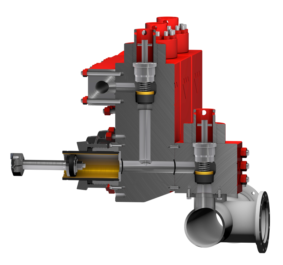
The 2,200-hp mud pump for offshore applications is a single-acting reciprocating triplex mud pump designed for high fluid flow rates, even at low operating speeds, and with a long stroke design. These features reduce the number of load reversals in critical components and increase the life of fluid end parts.
The pump’s critical components are strategically placed to make maintenance and inspection far easier and safer. The two-piece, quick-release piston rod lets you remove the piston without disturbing the liner, minimizing downtime when you’re replacing fluid parts.

This website is using a security service to protect itself from online attacks. The action you just performed triggered the security solution. There are several actions that could trigger this block including submitting a certain word or phrase, a SQL command or malformed data.

This website is using a security service to protect itself from online attacks. The action you just performed triggered the security solution. There are several actions that could trigger this block including submitting a certain word or phrase, a SQL command or malformed data.

This website is using a security service to protect itself from online attacks. The action you just performed triggered the security solution. There are several actions that could trigger this block including submitting a certain word or phrase, a SQL command or malformed data.

A mud pump is a piston driven pump design that can produce high-pressure operations to safely transfer high viscosity fluids over an extended depth. The mud pump has many applications in industrial service, but it has proven to be invaluable in many drilling operations. Let"s take a look at mud pumps and why they are such a good fit for the industries they serve.
A Mud pump is a reciprocal pump design utilizing a piston in a cylinder to transfer fluids under high pressure. A mud pump can generate up to 7,500 psi (52,000 kPa) during normal operations. Mud pumps are a positive displacement design.
Mud pumps are available in a variety of configurations and sizes. However, mud pumps tend to be one of two main types: the duplex and the triplex. The duplex mud pump features two pistons (or plungers) in constant action to move the fluid.
The triplex mud pump has all but replaced the duplex version in most applications, although you will still find the latter in use in some smaller countries. The triplex mud pump features a triple piston (plunger) design that is more efficient than the duplex design.
The latest designs of the mud pump are the quintuplex and hex versions. As the name suggests, these designs feature five or six pistons in a reciprocating design. Although not in widespread use as compared to the triplex design, these mud pumps spread the pumping action across the rotational cycle, creating less mud noise. This allows for better measurements and logging to take place while in operation.
There are two main parts to a mud pump: the fluid end and the power end. The fluid end is where the actual pumping takes place. The components of the fluid end consist of valves, pistons (or plungers), and liners.
Since the fluid end is in constant contact with the material being pumped, most modern designs allow for quick replacement of worn components as needed. This dramatically extends the life of a unit without having to completely replace the pump.
The power end of a mud pump is responsible for taking the input power, typically through a driveshaft, and converting it into the reciprocating motion needed for the pistons. In most mud pump applications, the power end uses a crosshead crankshaft for this conversion.
Rotational power is supplied to the mud pump through an external power source. The power end of the pump converts this rotational energy through a crankshaft to a reciprocating motion that moves the pistons.
The pistons move back and forth in their liners, exerting a force on the cylinder chamber. During the retraction of the piston, valves open to allow the fluid to be drawn into the cylinder. Once the piston has fully retracted, it is pushed back into the cylinder.
At this time the intake valves are closed and the exhaust valves open, allowing the piston to force the fluid out of the cylinder under pressure. Once the piston reaches its maximum depth into the cylinder, the exhaust valves close and the process repeats.
Due to the pressure and material being pumped, most mud pump applications can create a lot of vibration. To combat this, many mud pump applications incorporate pulsation dampeners. These are typically used on both suction and discharge sides of the pump.
In some cases, a positive displacement pump may pull the fluids at a pressure lower than its vapor pressure. When this happens, damaging cavitation can take place. In these cases, a charge pump might be required at the inlet side to maintain a positive pressure on the suction stream.
When selecting a mud pump, there are two main parameters to be used, pressure and displacement. Pressure is the net pumping pressure that the pump can safely provide. The requirement for pressure increases as the drilling depth and fluid (or slurry) viscosity increases.
Displacement is the volume of fluid that the pump can transfer within a given time period. In most applications, this is rated as discharged liters per minute.
Mud pumps are ideal wherever a lot of fluid needs to be pumped under high pressure. They are considered an essential part of most oil well drilling rigs. Mud pumps can deliver high concentration and high viscosity slurry in a stable flow, making them adaptable to many uses.
Mud pumps are an invaluable tool when high pressure and high viscosity fluids are needing to be transferred. Mader Electric, Inc. specializes in mud pump repair and installation, as well as pump training. Contact us to see how we can help with your pumping needs.

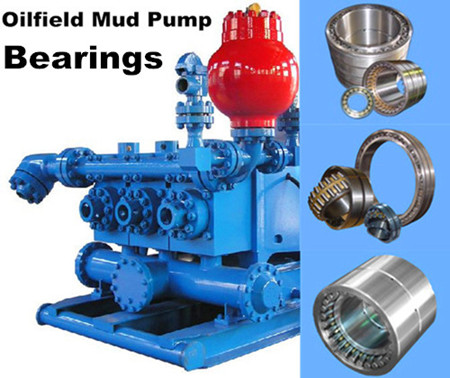
FET manufactures a full range of valves and seats for every drilling and well-servicing application as part of our full line of Osprey® mud pump system solutions. All of our valves and seats can be used in water, water base, oil base and synthetic base mud applications. FET offers additional valves and seats not listed below, including drilling valves, frac valves and well service valves. FET’s QC standards for the dimensional and material specs are extremely rigid in comparison to other manufacturers. Contact your FET representative to learn more.

All CategoriesAir compressors (2)Air compressor (1)Screw air (1)Attachments (2)Bucket (1)Screen (1)Backhoes (1)Excavators (1)Compactors (2)Compactor (1)Roller (1)Drill Rigs (1)Drilling (18)Brakes (1)Cat walk (1)Drilling Rig (1)Equipment (5)Mud Pits (3)Pipe wrangler (1)Pumps (3)Solids separation (3)Electrical Equipment (4)Circuit Breaker (1)Cutler Hammer (1)Eaton (1)Switchgear (1)Engines (24)Cores (2)Diesel (7)Drilling (2)Drilling Rig (1)Engine (5)Equipment (2)Natural Gas (2)Oilfield (1)Pump drive (1)Pumps (1)Generators (18)Cat (3)Diesel (7)Generator (7)John Deere (1)Heaters (3)Air heater (1)Blower (1)Indirect fired heater (1)Iron (2)Pipe (1)Sucker Rod (1)Man Camps (3)Man Camp (2)Rig House (1)Mud Pumps (27)1000hp (4)Cat (1)Diesel (2)Drilling (1)Emsco (3)Engine (1)Equipment (1)Mud pump (7)Pump (7)Natural Gas Compression (10)Compressor Station (3)Engine (1)Frick (2)Natural Gas (3)Waukesha (1)Oil Field (5)Bathroom (1)Shipping container (1)Substructure (1)Support Equipment (1)Tanks (1)Production (3)Injection (1)Pump (1)Pumping Unit (1)Rigs (1)Swabbing Unit (1)Road Graders (3)Blade (1)Road Grader (1)Service Trucks (1)Service Truck (1)Silos (2)Sand silos (1)Tanks (1)Support Equipment (19)Accumulator (3)Cat walk (1)Closing Unit (2)Drilling Rig (2)HPU (1)Koomey (2)Kubota (1)Mud pump (1)Oilfield (1)Pipe handling (1)Pipe rack (1)Pipe wrangler (1)Power Swivel (1)Tanks (1)Telehandler (4)Cat (1)Forklift (1)Reachlift (1)Telehandler (1)Trailer (4)Flatbed (1)Gooseneck (1)Step deck (1)Trailer (1)Valves (82)
Oil drilling is a challenging and highly mechanical profession. Oil rig operators need to have extensive knowledge of the tools they use, the correct processes for resource collection and how to recognize potential issues or risks and mitigate them. From drilling to worker safety, they"re responsible for many areas. One of the processes they need to know is swabbing.
Swabbing is a process that"s different for every well. It depends on preexisting pressurization, wellbore depth, fluid production from the reservoir and more. As you"re drilling, you may hit a point where you need to use a swabbing rig. At the very least, you can use the process to rejuvenate an old well. This guide will take you through the basics of oil well swabbing, why it"s important, how it works and some ways to decrease your chances of needing to swab a well.
As far as the oil and gas industry is concerned, swabbing is the act of accessing the production zones of wells and removing accumulated fracking fluids. It"s a method of well control that drilling companies use to release the well"s bottom hole pressure, allowing them to "kick" it off. When a drilling company creates a new well, they use pressurized liquids to fracture the site, creating channels and production zones where the oil and gas can travel. Swabbing follows as a second step.
To efficiently remove the remaining liquids from the well, teams use specific swabbing rigs, which consist of a winch, cable, swab cup, foldable mast and a pulley at the top. Once they"re ready to carry out the process, the rig operator will back the machine up to the edge of the well, as close as possible while still maintaining safety. They then adjust the rig"s mast and position it over the center point of the well. Using the winch, the operator lowers and raises the cable into and out of the well, keeping in mind control and the well"s characteristics.
In general, the standard for fluid removal is pulling about six barrels out of the well by way of the swabbing rig. In some cases, it only takes a single run, while other wells may require multiple repeats to remove all the fluids. As the operator pulls the fluids, the bottom pressure of the well builds, allowing the oil or gas to flow and push out of the well. Once you"ve reestablished the adequate pressure, your oilfield workers and operators can begin to pull resources from the well and store them.
However, the pressure doesn"t always last after the first swabbing. Over time, the pressure can decrease, causing the well to cease to produce oil or gas. If it depressurizes, the operator must apply the swabbing process again to build it back up. Swabbing rig operators must be highly skilled in their field, as they have to consider the soundness, pressure and depth of the well they"re working in, while also knowing the feel of their machine.
Well swabbing is essential to the production of oil and gas wells. For one, the process of swabbing and removing fluids from the production zone of the well creates the conditions for a gas and oil yield. The method introduces the pressure necessary for the well to push out the resources oilfield workers need to collect. If the well doesn"t have the required natural pressure to induce flowing on its own, swabbing makes it possible to access the resources regardless.
Additionally, as wells age, they collect fluids and lose their pressurization. But this doesn"t mean the well becomes unusable. If there are still resources left to pull, oilfield crews can use swabbing to rejuvenate the well"s pressurization multiple times. It removes those liquids that build up over time and with use.
When you pull resources from the reservoir, it also releases fluids that then collect at the bottom of the wellbore. As these liquids build up, they can prevent you from pulling oil or gas from the reservoir. Swabbing uses cups to remove the fluid, regaining you access to the oil well and allowing you to continue pulling resources. So, the process is necessary to get the most out of your wells.
If you aren"t sure why your well has ceased production, running an oil well swab test can provide you with a potential answer. Collecting fluid is a common reason for a reservoir production stoppage, and with a swab test, you can tell whether or not liquid is the problem. If it is, you can continue swabbing to pull as much as you need to remove from the reservoir area. If it"s not, you can rule it out as a possibility.
While swabbing is helpful in many cases, it isn"t always a necessary process. Some wells naturally have the required pressure to push oil out of themselves, and may not take on too much liquid over time. It all depends on the presence of particular factors and circumstances.
Fast pulling speeds: It takes a lot of energy to move mud at high speeds. Fast pulling from a well can create a more significant pressure drop and increase the need for swabbing. Monitoring the state of the well while tripping and making sure the pulling speed isn"t affecting well control are necessary to lessen the need for swabbing.
Balled-up bit or BHA: A balled-up bit and bottom hole assembly (BHA) creates a piston-like force and causes a much more significant swabbing effect. If you"re using a balled-up bit, you have to monitor the balance of the well"s condition. If the well has a nearly balanced status, it"s at a higher risk of becoming underbalanced due to the swabbing effect.
Large drilling tools: The size of the tools you use for tripping may significantly increase the potential need for swabbing. Using fishing tools, coring tools, mud motors, drill collars or any other form of large apparatus may cause a need for swabbing. You can still use these tools, but your operators and team need to understand how to use them carefully to trip the well. With proper attention, you can use them and prevent the need for swabbing.
Mud thickness and properties: The viscosity of the mud you"re moving comes into play as well. When mud is thick and has a high viscosity, it takes much more energy to move. That added thickness and energy use creates a pressure drop, which sometimes causes a need for swabbing. Beyond viscosity, several other mud properties can affect the pressure, such as high rheology and high gel strength, which can induce swab kick. Since these properties matter so much, it"s essential to keep an eye on the drilling fluids, monitor their properties and have a plan in place to keep the mud in the best condition possible.
Hydrostatic vs. formation pressure: The balance of your well"s condition includes hydrostatic and formation pressure. To create the best possible environment, you have to ensure there"s an overbalance margin with a higher formation pressure. If the hydrostatic pressure is above or equal to the formation, the chance of swabbing increases greatly.
Small hole clearance: The size of the access hole can also affect whether or not you may need swabbing. Moving mud through a bore with the proper amount of clearance should pose no problem, as long as the other elements align properly. But pulling mud through a hole with a smaller space uses much more energy, causing a more significant drop in pressure and a potential need for swabbing.
Formation movement: Sometimes, the formation itself can pose an issue. With swelling and heaving, the wellbore may decrease in size, creating a smaller diameter and a tighter space for the BHA or bit. Pulling out of the well with a small clearance can increase the chances of needing swabbing in drilling.
The process of swabbing involves specialized equipment and well-trained operators. To start, you should follow the recommended OSHA regulations and precautions, which include details like conducting swabbing during daylight hours, keeping oilfield workers significantly clear of the well and equipment at all times and locating swab tanks a proper distance from the well site.
First, you need to be able to recognize when swabbing is necessary. As you pull oil from your well, it is exiting the reservoirs through perforations. The openings may also produce fluids. But rather than travel up the pipe, they collect in the bottom of the well. As the fluid levels get higher, they block off the reservoir, causing it to stop producing. Swabbing equipment will help you remove the liquid without disturbing the reserve, allowing you to continue pulling from it.
Next, you need the right equipment. Swabbing cups are specifically for removing liquids from wells. As you push them into the well, they allow water to push past them, dipping into the collected fluids. However, they only allow fluids to pass in one direction. It works similarly to a loose plunger in a syringe tube, for the sake of visual representation.
As you pull the cups back out of the well, they pull the liquids that passed with them, effectively removing them from the wellbore. Depending on how much fluid has accumulated, you may need to repeat the process multiple times for the well to continue producing.
Once the fluid level is low enough, you can continue pulling from the well. The remaining bit of liquid will rise with the oil as you proceed and return the reservoir to full productivity. Over time, the fluid will gather again and require another swabbing treatment, but there are ways you can minimize the number of times you need to swab a particular well.
Swabbing a well can be time-consuming and costly for your company, as well as harmful for the environment. The act of swabbing a well can cause the well to vent a significant amount of methane emissions per year. A single well can create anywhere from 80 to 1,600 thousand cubic feet (Mcf) of methane in a year, depending on how often it requires swabbing. Minimizing the chances of swabbing is beneficial for your company and the environment.
Maintaining well control: One of the best ways to prevent the occurrence of swabbing is to retain control over the well by any means necessary. Continually monitor it and ensure all systems are working correctly. Whenever you observe any indications that swabbing might become necessary, it"s essential to have a plan to control the conditions. Whether you find signs of swelling, narrow access, imbalanced pressures or a difference in mud viscosity, having a way to regain control is imperative.
Monitoring mud condition:The conditions of the well as a whole are essential to maintaining safety and mitigating risks, but you should also keep a close eye on the status of your mud. The mud surrounding your equipment can make your job easier or much harder, depending on a few factors. If your mud has a high viscosity, rheology or gel strength, you"re dealing with poor conditions that can cause bit balling and induced swab kick. If you monitor it, you can help control these factors through proper lubrication and using the correct type of chemicals. Lowering the viscosity of the mud will help you mitigate swabbing risks.
Preventing bit balling:There are several reasons your bit and BHA can ball up during the drilling process. It could be due to clay and shale collecting on the equipment, too much weight on the bit, an imbalance in pressure where the hydrostatic pressure is too high or a poor bit design and structure. There are several ways you can recognize if your bit is balled up while drilling, such as a low drilling torque, a decreased rate of penetration or an increased standpipe pressure. Catching any of these early by consistent monitoring will reduce your chances of swabbing. You can also use preventative measures to decrease your chances before drilling, such as selecting reliable equipment, adding a reasonable amount of weight to the bit, using proper drilling fluid and lubricant and ensuring you have enough hydraulic horsepower.
Pull out of the well at reasonable speed: A simple way to avoid issues with swabbing is to monitor your speeds. Pulling out of your well too fast can affect its pressure balance, causing it to drop significantly. Well-balanced pressure is essential to keeping your oil well controlled and minimize the potential for swabbing.
Pumping instead of pulling: While monitoring your pulling speeds is a great way to mitigate any risks, you can also decrease the number of times you need to remove fluids by pumping instead. With pumping, there"s less risk for the damages associated with pulling, such as depressurization, making it useful for minimizing swabbing.
Having reliable equipment is essential to ensuring you can continue your oil pulling operations. High-quality apparatus can keep your rig from suffering downtime or many of the drilling-related hardware damages. With Global Elastomeric Products, you"ll have access to standard and custom oilfield equipment, proudly made in the U.S. with top quality materials. From swab cups and accessories to custom rubber molding, we can provide your company with the solutions it needs to keep your rigs up and running.
Global Elastomeric Products has over 50 years in the industry and ISO certification. Our team of in-house design engineers can help you through the process of choosing the right parts or customizing your mold. We make the process as straightforward as possible and guarantee a quick turnaround.
Gardner Denver, Lewco, NOV, Oilwell, National, Varco, Woolley, Baash-Ross, Demco, Bomco, Oteco, Brown & Sharpe, Ideco, P-Quip, and Continental Emsco, and the product models referenced on this website are trademarks or registered trademarks of their respective companies. Premium Oilfield Technologies is not authorized by or affiliated with any of these companies, and no business relationship, affiliation, or endorsement is claimed or implied.


 8613371530291