
what is a swab on a mud pump free sample
If you run a mud rig, you have probably figured out that the mud pump is the heart of the rig. Without it, drilling stops. Keeping your pump in good shape is key to productivity. There are some tricks I have learned over the years to keeping a pump running well.
First, you need a baseline to know how well your pump is doing. When it’s freshly rebuilt, it will be at the top efficiency. An easy way to establish this efficiency is to pump through an orifice at a known rate with a known fluid. When I rig up, I hook my water truck to my pump and pump through my mixing hopper at idle. My hopper has a ½-inch nozzle in it, so at idle I see about 80 psi on the pump when it’s fresh. Since I’m pumping clear water at a known rate, I do this on every job.
As time goes on and I drill more hole, and the pump wears, I start seeing a decrease in my initial pressure — 75, then 70, then 65, etc. This tells me I better order parts. Funny thing is, I don’t usually notice it when drilling. After all, I am running it a lot faster, and it’s hard to tell the difference in a few gallons a minute until it really goes south. This method has saved me quite a bit on parts over the years. When the swabs wear they start to leak. This bypass pushes mud around the swab, against the liners, greatly accelerating wear. By changing the swab at the first sign of bypass, I am able to get at least three sets of swabs before I have to change liners. This saves money.
Before I figured this out, I would sometimes have to run swabs to complete failure. (I was just a hand then, so it wasn’t my rig.) When I tore the pump down to put in swabs, lo-and-behold, the liners were cut so badly that they had to be changed too. That is false economy. Clean mud helps too. A desander will pay for itself in pump parts quicker than you think, and make a better hole to boot. Pump rods and packing last longer if they are washed and lubricated. In the oilfield, we use a petroleum-based lube, but that it not a good idea in the water well business. I generally use water and dish soap. Sometimes it tends to foam too much, so I add a few tablets of an over the counter, anti-gas product, like Di-Gel or Gas-Ex, to cut the foaming.
Maintenance on the gear end of your pump is important, too. Maintenance is WAY cheaper than repair. The first, and most important, thing is clean oil. On a duplex pump, there is a packing gland called an oil-stop on the gear end of the rod. This is often overlooked because the pump pumps just as well with a bad oil-stop. But as soon as the fluid end packing starts leaking, it pumps mud and abrasive sand into the gear end. This is a recipe for disaster. Eventually, all gear ends start knocking. The driller should notice this, and start planning. A lot of times, a driller will change the oil and go to a higher viscosity oil, thinking this will help cushion the knock. Wrong. Most smaller duplex pumps are splash lubricated. Thicker oil does not splash as well, and actually starves the bearings of lubrication and accelerates wear. I use 85W90 in my pumps. A thicker 90W140 weight wears them out a lot quicker. You can improve the “climbing” ability of the oil with an additive, like Lucas, if you want. That seems to help.
Outside the pump, but still an important part of the system, is the pop-off, or pressure relief valve. When you plug the bit, or your brother-in-law closes the discharge valve on a running pump, something has to give. Without a good, tested pop-off, the part that fails will be hard to fix, expensive and probably hurt somebody. Pop-off valve are easily overlooked. If you pump cement through your rig pump, it should be a standard part of the cleanup procedure. Remove the shear pin and wash through the valve. In the old days, these valves were made to use a common nail as the shear pin, but now nails come in so many grades that they are no longer a reliable tool. Rated shear pins are available for this. In no case should you ever run an Allen wrench! They are hardened steel and will hurt somebody or destroy your pump.
One last thing that helps pump maintenance is a good pulsation dampener. It should be close to the pump discharge, properly sized and drained after every job. Bet you never thought of that one. If your pump discharge goes straight to the standpipe, when you finish the job your standpipe is still full of fluid. Eventually the pulsation dampener will water-log and become useless. This is hard on the gear end of the pump. Open a valve that drains it at the end of every job. It’ll make your pump run smoother and longer.

As usual, winter — or the slow season — is the time most drillers take the time to maintain their equipment in order to get ready for the peak season. One of the main parts that usually needs attention is the mud pump. Sometimes, it is just a set of swabs to bring it up to snuff, but often, tearing it down and inspecting the parts may reveal that other things need attention. For instance, liners. I can usually run three sets of swabs before it is time to change the liner. New liners and swabs last a good long time. The second set of swabs lasts less, and by the time you put in your third set of swabs, it’s time to order new liners. Probably rods too. It’s not always necessary to change pistons when you change swabs. Sometimes just the rubber needs to be changed, saving money. How do you tell? There is a small groove around the outside of the piston. As it wears, the groove will disappear and it’s time for a new piston.
The wear groove on a piston can be a good indicator of the general health of your pump. If the wear is pretty even all around, chances are the pump is in pretty good shape. But if you see wear on one side only, that is a clue to dig deeper. Uneven wear is a sign that the rods are not stroking at the exact angle that they were designed to, which is parallel to the liner. So, it’s time to look at the gear end. Or as some folks call it, “the expensive end.”
The wear groove on a piston can be a good indicator of the general health of your pump. If the wear is pretty even all around, chances are the pump is in pretty good shape. But if you see wear on one side only, that is a clue to dig deeper.
After you get the cover off the gear end, the first thing to look at will be the oil. It needs to be fairly clean, with no drill mud in it. Also look for metal. Some brass is to be expected, but if you put a magnet in the oil and come back later and it has more than a little metal on it, it gets more serious. The brass in the big end of the connecting rod is a wearable part. It is made to be replaced at intervals — usually years. The most common source of metal is from the bull and pinion gears. They transmit the power to the mud. If you look at the pinion gear closely, you will find that it wears faster than the bull gear. This is for two reasons. First, it is at the top of the pump and may not receive adequate lubrication. The second reason is wear. All the teeth on both the bull and pinion gears receive the same amount of wear, but the bull gear has many more teeth to spread the wear. That is why, with a well maintained pump, the bull gear will outlast the pinion gear three, four or even five times. Pinion gears aren’t too expensive and are fairly easy to change.
If the gears look OK and there are no obvious bearing problems, the next parts to look at are the crank journals; they ride in the brass at the big end of the rod and take plenty of abuse. This is where it gets interesting. To repair or replace is the big question. Replacement is pretty expensive and you may have to wait a while. Repairs are more my style because I know some excellent machinists and can tell them exactly what I need done. If your journals are deeply scored, you will have to turn the crank. It takes a pretty special machine to do this, but one of my friends has one and is a master with it. The procedure is to turn down the journals and press a steel sleeve over them, bringing them up to factory new specs.
This process is fairly straightforward machine work, but over the years, I have discovered a trick that will bring a rebuild up to “better than new.” When you tear a pump down, did you ever notice that there is about 1-inch of liner on each end that has no wear? This is because the swab never gets to it. If it has wear closer to one end than the other, your rods are out of adjustment. The trick is to offset grind the journals. I usually offset mine about ¼-inch. This gives me a ½-inch increase in the stroke without weakening the gear end. This turns a 5x6 pump into a 5½x6 pump. More fluid equals better holes. I adjust the rods to the right length to keep from running out the end of the liner, and enjoy the benefits.
Other than age, the problem I have seen with journal wear is improper lubrication. Smaller pumps rely on splash lubrication. This means that as the crank strokes, the rods pick up oil and it lubricates the crank journals. If your gear end is full of drill mud due to bad packing, it’s going to eat your pump. If the oil is clean, but still shows crank wear, you need to look at the oil you are using.
Oil that is too thick will not be very well picked up and won’t find its way into the oil holes in the brass to lubricate the journals. I’ve seen drillers that, when their pump starts knocking, they switch to a heavier weight oil. This actually makes the problem worse. In my experience, factory specified gear end oil is designed for warmer climates. As you move north, it needs to be lighter to do its job. Several drillers I know in the Northern Tier and Canada run 30 weight in their pumps. In Georgia, I run 40W90. Seems to work well.

Oil drilling is a challenging and highly mechanical profession. Oil rig operators need to have extensive knowledge of the tools they use, the correct processes for resource collection and how to recognize potential issues or risks and mitigate them. From drilling to worker safety, they"re responsible for many areas. One of the processes they need to know is swabbing.
Swabbing is a process that"s different for every well. It depends on preexisting pressurization, wellbore depth, fluid production from the reservoir and more. As you"re drilling, you may hit a point where you need to use a swabbing rig. At the very least, you can use the process to rejuvenate an old well. This guide will take you through the basics of oil well swabbing, why it"s important, how it works and some ways to decrease your chances of needing to swab a well.
As far as the oil and gas industry is concerned, swabbing is the act of accessing the production zones of wells and removing accumulated fracking fluids. It"s a method of well control that drilling companies use to release the well"s bottom hole pressure, allowing them to "kick" it off. When a drilling company creates a new well, they use pressurized liquids to fracture the site, creating channels and production zones where the oil and gas can travel. Swabbing follows as a second step.
To efficiently remove the remaining liquids from the well, teams use specific swabbing rigs, which consist of a winch, cable, swab cup, foldable mast and a pulley at the top. Once they"re ready to carry out the process, the rig operator will back the machine up to the edge of the well, as close as possible while still maintaining safety. They then adjust the rig"s mast and position it over the center point of the well. Using the winch, the operator lowers and raises the cable into and out of the well, keeping in mind control and the well"s characteristics.
In general, the standard for fluid removal is pulling about six barrels out of the well by way of the swabbing rig. In some cases, it only takes a single run, while other wells may require multiple repeats to remove all the fluids. As the operator pulls the fluids, the bottom pressure of the well builds, allowing the oil or gas to flow and push out of the well. Once you"ve reestablished the adequate pressure, your oilfield workers and operators can begin to pull resources from the well and store them.
However, the pressure doesn"t always last after the first swabbing. Over time, the pressure can decrease, causing the well to cease to produce oil or gas. If it depressurizes, the operator must apply the swabbing process again to build it back up. Swabbing rig operators must be highly skilled in their field, as they have to consider the soundness, pressure and depth of the well they"re working in, while also knowing the feel of their machine.
Well swabbing is essential to the production of oil and gas wells. For one, the process of swabbing and removing fluids from the production zone of the well creates the conditions for a gas and oil yield. The method introduces the pressure necessary for the well to push out the resources oilfield workers need to collect. If the well doesn"t have the required natural pressure to induce flowing on its own, swabbing makes it possible to access the resources regardless.
Additionally, as wells age, they collect fluids and lose their pressurization. But this doesn"t mean the well becomes unusable. If there are still resources left to pull, oilfield crews can use swabbing to rejuvenate the well"s pressurization multiple times. It removes those liquids that build up over time and with use.
When you pull resources from the reservoir, it also releases fluids that then collect at the bottom of the wellbore. As these liquids build up, they can prevent you from pulling oil or gas from the reservoir. Swabbing uses cups to remove the fluid, regaining you access to the oil well and allowing you to continue pulling resources. So, the process is necessary to get the most out of your wells.
If you aren"t sure why your well has ceased production, running an oil well swab test can provide you with a potential answer. Collecting fluid is a common reason for a reservoir production stoppage, and with a swab test, you can tell whether or not liquid is the problem. If it is, you can continue swabbing to pull as much as you need to remove from the reservoir area. If it"s not, you can rule it out as a possibility.
While swabbing is helpful in many cases, it isn"t always a necessary process. Some wells naturally have the required pressure to push oil out of themselves, and may not take on too much liquid over time. It all depends on the presence of particular factors and circumstances.
Fast pulling speeds: It takes a lot of energy to move mud at high speeds. Fast pulling from a well can create a more significant pressure drop and increase the need for swabbing. Monitoring the state of the well while tripping and making sure the pulling speed isn"t affecting well control are necessary to lessen the need for swabbing.
Balled-up bit or BHA: A balled-up bit and bottom hole assembly (BHA) creates a piston-like force and causes a much more significant swabbing effect. If you"re using a balled-up bit, you have to monitor the balance of the well"s condition. If the well has a nearly balanced status, it"s at a higher risk of becoming underbalanced due to the swabbing effect.
Large drilling tools: The size of the tools you use for tripping may significantly increase the potential need for swabbing. Using fishing tools, coring tools, mud motors, drill collars or any other form of large apparatus may cause a need for swabbing. You can still use these tools, but your operators and team need to understand how to use them carefully to trip the well. With proper attention, you can use them and prevent the need for swabbing.
Mud thickness and properties: The viscosity of the mud you"re moving comes into play as well. When mud is thick and has a high viscosity, it takes much more energy to move. That added thickness and energy use creates a pressure drop, which sometimes causes a need for swabbing. Beyond viscosity, several other mud properties can affect the pressure, such as high rheology and high gel strength, which can induce swab kick. Since these properties matter so much, it"s essential to keep an eye on the drilling fluids, monitor their properties and have a plan in place to keep the mud in the best condition possible.
Hydrostatic vs. formation pressure: The balance of your well"s condition includes hydrostatic and formation pressure. To create the best possible environment, you have to ensure there"s an overbalance margin with a higher formation pressure. If the hydrostatic pressure is above or equal to the formation, the chance of swabbing increases greatly.
Small hole clearance: The size of the access hole can also affect whether or not you may need swabbing. Moving mud through a bore with the proper amount of clearance should pose no problem, as long as the other elements align properly. But pulling mud through a hole with a smaller space uses much more energy, causing a more significant drop in pressure and a potential need for swabbing.
Formation movement: Sometimes, the formation itself can pose an issue. With swelling and heaving, the wellbore may decrease in size, creating a smaller diameter and a tighter space for the BHA or bit. Pulling out of the well with a small clearance can increase the chances of needing swabbing in drilling.
The process of swabbing involves specialized equipment and well-trained operators. To start, you should follow the recommended OSHA regulations and precautions, which include details like conducting swabbing during daylight hours, keeping oilfield workers significantly clear of the well and equipment at all times and locating swab tanks a proper distance from the well site.
First, you need to be able to recognize when swabbing is necessary. As you pull oil from your well, it is exiting the reservoirs through perforations. The openings may also produce fluids. But rather than travel up the pipe, they collect in the bottom of the well. As the fluid levels get higher, they block off the reservoir, causing it to stop producing. Swabbing equipment will help you remove the liquid without disturbing the reserve, allowing you to continue pulling from it.
Next, you need the right equipment. Swabbing cups are specifically for removing liquids from wells. As you push them into the well, they allow water to push past them, dipping into the collected fluids. However, they only allow fluids to pass in one direction. It works similarly to a loose plunger in a syringe tube, for the sake of visual representation.
As you pull the cups back out of the well, they pull the liquids that passed with them, effectively removing them from the wellbore. Depending on how much fluid has accumulated, you may need to repeat the process multiple times for the well to continue producing.
Once the fluid level is low enough, you can continue pulling from the well. The remaining bit of liquid will rise with the oil as you proceed and return the reservoir to full productivity. Over time, the fluid will gather again and require another swabbing treatment, but there are ways you can minimize the number of times you need to swab a particular well.
Swabbing a well can be time-consuming and costly for your company, as well as harmful for the environment. The act of swabbing a well can cause the well to vent a significant amount of methane emissions per year. A single well can create anywhere from 80 to 1,600 thousand cubic feet (Mcf) of methane in a year, depending on how often it requires swabbing. Minimizing the chances of swabbing is beneficial for your company and the environment.
Maintaining well control: One of the best ways to prevent the occurrence of swabbing is to retain control over the well by any means necessary. Continually monitor it and ensure all systems are working correctly. Whenever you observe any indications that swabbing might become necessary, it"s essential to have a plan to control the conditions. Whether you find signs of swelling, narrow access, imbalanced pressures or a difference in mud viscosity, having a way to regain control is imperative.
Monitoring mud condition:The conditions of the well as a whole are essential to maintaining safety and mitigating risks, but you should also keep a close eye on the status of your mud. The mud surrounding your equipment can make your job easier or much harder, depending on a few factors. If your mud has a high viscosity, rheology or gel strength, you"re dealing with poor conditions that can cause bit balling and induced swab kick. If you monitor it, you can help control these factors through proper lubrication and using the correct type of chemicals. Lowering the viscosity of the mud will help you mitigate swabbing risks.
Preventing bit balling:There are several reasons your bit and BHA can ball up during the drilling process. It could be due to clay and shale collecting on the equipment, too much weight on the bit, an imbalance in pressure where the hydrostatic pressure is too high or a poor bit design and structure. There are several ways you can recognize if your bit is balled up while drilling, such as a low drilling torque, a decreased rate of penetration or an increased standpipe pressure. Catching any of these early by consistent monitoring will reduce your chances of swabbing. You can also use preventative measures to decrease your chances before drilling, such as selecting reliable equipment, adding a reasonable amount of weight to the bit, using proper drilling fluid and lubricant and ensuring you have enough hydraulic horsepower.
Pull out of the well at reasonable speed: A simple way to avoid issues with swabbing is to monitor your speeds. Pulling out of your well too fast can affect its pressure balance, causing it to drop significantly. Well-balanced pressure is essential to keeping your oil well controlled and minimize the potential for swabbing.
Pumping instead of pulling: While monitoring your pulling speeds is a great way to mitigate any risks, you can also decrease the number of times you need to remove fluids by pumping instead. With pumping, there"s less risk for the damages associated with pulling, such as depressurization, making it useful for minimizing swabbing.
Having reliable equipment is essential to ensuring you can continue your oil pulling operations. High-quality apparatus can keep your rig from suffering downtime or many of the drilling-related hardware damages. With Global Elastomeric Products, you"ll have access to standard and custom oilfield equipment, proudly made in the U.S. with top quality materials. From swab cups and accessories to custom rubber molding, we can provide your company with the solutions it needs to keep your rigs up and running.
Global Elastomeric Products has over 50 years in the industry and ISO certification. Our team of in-house design engineers can help you through the process of choosing the right parts or customizing your mold. We make the process as straightforward as possible and guarantee a quick turnaround.

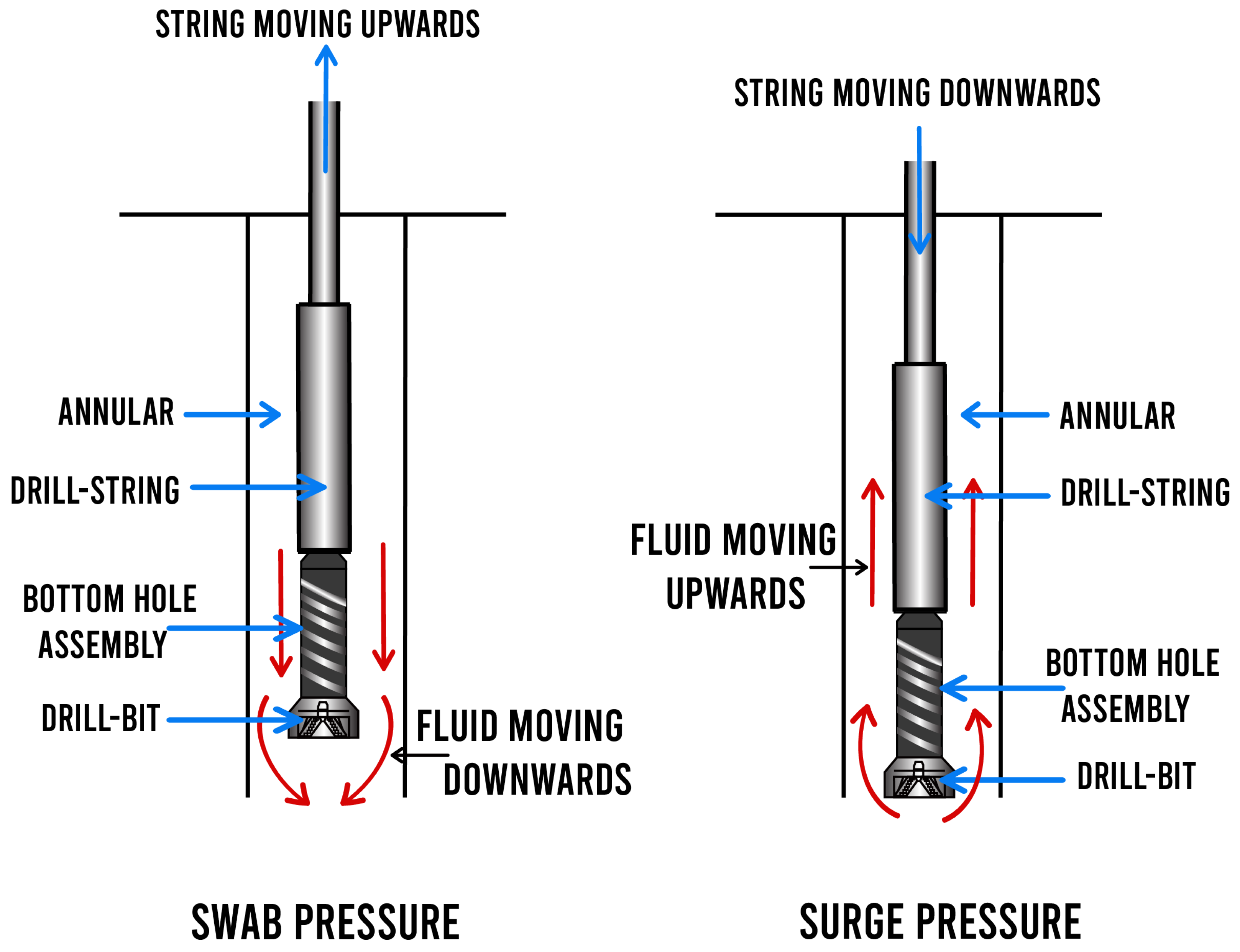
Swabbing is when bottom hole pressure is reduced below formation pressure due to the effects of pulling the drill string, which allows an influx of formation fluids into the wellbore.
When pulling the string there will always be some variation to bottom hole pressure. A pressure loss is caused by friction, the friction between the mud and the drill string being pulled. Swabbing can also be caused by the full gauge down hole tools (bits, stabilisers, reamers, core barrels, etc.) being balled up. This can create a piston like effect when they are pulled through mud. This type of swabbing can have drastic effects on bottom hole pressure.
Surging is when the bottom hole pressure is increased due to the effects of running the drill string too fast in the hole. Down hole mud losses may occur if care is not taken and fracture pressure is exceeded while RIH. Proper monitoring of the displacement volume with the trip tank is required at all times.
Swabbing is a recognised hazard whether it is "low" volume swabbing or "high" volume swabbing. A small influx volume may be swabbed into the open hole section. The net decrease in hydrostatics due to this low density fluid will also be small. If the influx fluid is gas it can of course migrate and expand. The expansion may occur when there is little or no pipe left in the hole. The consequences of running pipe into the hole and into swabbed gas must also be considered.
Tripping speeds must be controlled to reduce the possibility of swabbing. It is normal practice for the Mud Logger to run a swab and surge programme and to make this information available to the Driller. This will provide ample information to reduce the possibility of unforeseen influx occurring.
If swabbing has been detected and the well is not flowing a non return valve should be installed and the bit returned to bottom. Flow check each stand. Once back on bottom the well should be circulated and the bottoms up sample checked for contamination.
Continuous monitoring of replacement and displacement volumes is essential when performing tripping. A short wiper trip and circulating the well before pulling completely out of the hole will provide useful information about swabbing and pulling speeds.
Another cause for a kick to occur is the reduction of hydrostatic pressure through loss of drilling fluid to the formation during lost circulation. When this happens, the height of the mud column is shortened, thus decreasing the pressure on the bottom and at all other depths in the hole.
The amount the mud column can be shortened before taking a kick from a permeable zone can be calculated by dividing the mud gradient into the overbalance at the top of the permeable kick zone.
A kick can occur if a permeable formation is drilled which has a higher pressure than that exerted by the mud column. If the overpressurised formations have low permeability then traces of the formation fluid should be detected in the returns after circulating bottoms up. If the overpressured formations have a high permeability then the risk is greater and the well should be shut-in as soon as flow is detected.
A further cause of kicks from drilling accidentally into abnormally pressured permeable zones. This is because we had ignored the warning signals that occur, these help us detect abnormal pressures. Some of these warning signals are: an increased penetration rate, an increase in background gas or gas cutting of the mud, a decrease in shale density, an increase in cutting size, or an increase in flow-line temperature, etc.
In some areas, there were adequate sands that were continuous and open into the sea or to the surface. In these areas the water squeezed from the shale formations, travelled through the permeable sands and was released to the sea or to a surface outcrop. This de-watering allowed the formations to continue to compact and thereby increase their density.
In other areas, or at other times, the sands did not develop or were sealed by deposition of salt or other impervious formations, or by faulting such as we have indicated here. Although the shale water was squeezed, it could not escape. Since water is nearly incompressible, the shales could not compress past the point where the water in the shale started to bear the weight of the rock above. This section caused a condition in which the weight of the formation - that is, the overburden -was borne not by the shale alone, but assisted by the fluids in the shale. In this situation the shale will have more porosity, and a lower density, than they would have had if the now pressured water had been allowed to escape. These formations, both sand and shale, are then overpressured. If a hole is drilled into an overpressured formation, weighted mud will be required to hold back the fluids contained in the pore space.

If you ended up on this page doing normal allowed operations, please contact our support at support@mdpi.com. Please include what you were doing when this page came up and the Ray ID & Your IP found at the

This website is using a security service to protect itself from online attacks. The action you just performed triggered the security solution. There are several actions that could trigger this block including submitting a certain word or phrase, a SQL command or malformed data.

to change the supplier / type. The thinking is that "Bonded White Lightning" (Mission) components are designed for a bit higher temperature environment (230 deg F vs 208 deg F at section TD) and might be a bit "stiff" and have issues "adjusting" to the inner bore, bypassing fluid and eventually failing due to wash-out.
A kick is a well control problem in which the pressure found within the drilled rock is higher than the mud hydrostatic pressure acting on the borehole or rock face. When this occurs, the greater formation pressure has a tendency to force formation fluids into the wellbore. This forced fluid flow is called a kick. If the flow is successfully controlled, the kick is considered to have been killed. An uncontrolled kick that increases in severity may result in what is known as a “blowout.”
Several factors affect the severity of a kick. One factor, for example, is the “permeability” of rock, which is its ability to allow fluid to move through the rock. Another factor affecting kick severity is “porosity.” Porosity measures the amount of space in the rock containing fluids. A rock with high permeability and high porosity has greater potential for a severe kick than a rock with low permeability and low porosity. For example, sandstone is considered to have greater kick potential than shale, because sandstone has greater permeability and greater porosity than shale.
Yet another factor affecting kick severity is the “pressure differential” involved. Pressure differential is the difference between the formation fluid pressure and the mud hydrostatic pressure. If the formation pressure is much greater than the hydrostatic pressure, a large negative differential pressure exists. If this negative differential pressure is coupled with high permeability and high porosity, a severe kick may occur.
A kick can be labeled in several ways, including one that depends on the type of formation fluid that entered the borehole. Known kick fluids include:
If gas enters the borehole, the kick is called a "gas kick." Furthermore, if a volume of 20 bbl (3.2 m3) of gas entered the borehole, the kick could be termed a 20-bbl (3.2-m3) gas kick.
Another way of labeling kicks is by identifying the required mud weight increase necessary to control the well and kill a potential blowout. For example, if a kick required a 0.7-lbm/gal (84-kg/m3) mud weight increase to control the well, the kick could be termed a 0.7-lbm/gal (84-kg/m3) kick. It is interesting to note that an average kick requires approximately 0.5 lbm/gal (60 kg/m3), or less, mud weight increase.
Kicks occur as a result of formation pressure being greater than mud hydrostatic pressure, which causes fluids to flow from the formation into the wellbore. In almost all drilling operations, the operator attempts to maintain a hydrostatic pressure greater than formation pressure and, thus, prevent kicks; however, on occasion the formation will exceed the mud pressure and a kick will occur. Reasons for this imbalance explain the key causes of kicks:
Insufficient mud weight is the predominant cause of kicks. A permeable zone is drilled while using a mud weight that exerts less pressure than the formation pressure within the zone. Because the formation pressure exceeds the wellbore pressure, fluids begin to flow from the formation into the wellbore and the kick occurs.
These abnormal formation pressures are often associated with causes for kicks. Abnormal formation pressures are greater pressures than in normal conditions. In well control situations, formation pressures greater than normal are the biggest concern. Because a normal formation pressure is equal to a full column of native water, abnormally pressured formations exert more pressure than a full water column. If abnormally pressured formations are encountered while drilling with mud weights insufficient to control the zone, a potential kick situation has developed. Whether or not the kick occurs depends on the permeability and porosity of the rock. A number of abnormal pressure indicators can be used to estimate formation pressures so that kicks caused by insufficient mud weight are prevented (some are listed in Table 1).
An obvious solution to kicks caused by insufficient mud weights seems to be drilling with high mud weights; however, this is not always a viable solution. First, high mud weights may exceed the fracture mud weight of the formation and induce lost circulation. Second, mud weights in excess of the formation pressure may significantly reduce the penetration rates. Also, pipe sticking becomes a serious consideration when excessive mud weights are used. The best solution is to maintain a mud weight slightly greater than formation pressure until the mud weight begins to approach the fracture mud weight and, thus, requires an additional string of casing.
Improperly filling up of the hole during trips is another prominent cause of kicks. As the drillpipe is pulled out of the hole, the mud level falls because the pipe steel no longer displaces the mud. As the overall mud level decreases, the hole must be periodically filled up with mud to avoid reducing the hydrostatic pressure and, thereby, allowing a kick to occur.
Several methods can be used to fill up the hole, but each must be able to accurately measure the amount of mud required. It is not acceptable—under any condition—to allow a centrifugal pump to continuously fill up the hole from the suction pit because accurate mud-volume measurement with this sort of pump is impossible. The two acceptable methods most commonly used to maintain hole fill-up are the trip-tank method and the pump-stroke measurements method.
The trip-tank method has a calibration device that monitors the volume of mud entering the hole. The tank can be placed above the preventer to allow gravity to force mud into the annulus, or a centrifugal pump may pump mud into the annulus with the overflow returning to the trip tank. The advantages of the trip-tank method include that the hole remains full at all times, and an accurate measurement of the mud entering the hole is possible.
The other method of keeping a full hole—the pump-stroke measurement method—is to periodically fill up the hole with a positive-displacement pump. A flowline device can be installed with the positive-displacement pump to measure the pump strokes required to fill the hole. This device will automatically shut off the pump when the hole is full.
Pulling the drillstring from the borehole creates swab pressures. Swab pressures are negative, and reduce the effective hydrostatic pressure throughout the hole and below the bit. If this pressure reduction lowers the effective hydrostatic pressure below the formation pressure, a potential kick has developed. Variables controlling swab pressures are:
Gas-contaminated mud will occasionally cause a kick, although this is rare. The mud density reduction is usually caused by fluids from the core volume being cut and released into the mud system. As the gas is circulated to the surface, it expands and may reduce the overall hydrostatic pressure sufficient enough to allow a kick to occur.
Although the mud weight is cut severely at the surface, the hydrostatic pressure is not reduced significantly because most gas expansion occurs near the surface and not at the hole bottom.
Occasionally, kicks are caused by lost circulation. A decreased hydrostatic pressure occurs from a shorter mud column. When a kick occurs from lost circulation, the problem may become severe. A large volume of kick fluid may enter the hole before the rising mud level is observed at the surface. It is recommended that the hole be filled with some type of fluid to monitor fluid levels if lost circulation occurs.
Warning signs and possible kick indicators can be observed at the surface. Each crew member has the responsibility to recognize and interpret these signs and take proper action. All signs do not positively identify a kick; some merely warn of potential kick situations. Key warning signs to watch for include the following:
An increase in flow rate leaving the well, while pumping at a constant rate, is a primary kick indicator. The increased flow rate is interpreted as the formation aiding the rig pumps by moving fluid up the annulus and forcing formation fluids into the wellbore.
If the pit volume is not changed as a result of surface-controlled actions, an increase indicates a kick is occurring. Fluids entering the wellbore displace an equal volume of mud at the flowline, resulting in pit gain.
When the rig pumps are not moving the mud, a continued flow from the well indicates a kick is in progress. An exception is when the mud in the drillpipe is considerably heavier than in the annulus, such as in the case of a slug.
A pump pressure change may indicate a kick. Initial fluid entry into the borehole may cause the mud to flocculate and temporarily increase the pump pressure. As the flow continues, the low-density influx will displace heavier drilling fluids, and the pump pressure may begin to decrease. As the fluid in the annulus becomes less dense, the mud in the drillpipe tends to fall and pump speed may increase.
Other drilling problems may also exhibit these signs. A hole in the pipe, called a “washout,” will cause pump pressure to decrease. A twist-off of the drillstring will give the same signs. It is proper procedure, however, to check for a kick if these signs are observed.
When the drillstring is pulled out of the hole, the mud level should decrease by a volume equivalent to the removed steel. If the hole does not require the calculated volume of mud to bring the mud level back to the surface, it is assumed a kick fluid has entered the hole and partially filled the displacement volume of the drillstring. Even though gas or salt water may have entered the hole, the well may not flow until enough fluid has entered to reduce the hydrostatic pressure below the formation pressure.
Drilling fluid provides a buoyant effect to the drillstring and reduces the actual pipe weight supported by the derrick. Heavier muds have a greater buoyant force than less dense muds. When a kick occurs, and low-density formation fluids begin to enter the borehole, the buoyant force of the mud system is reduced, and the string weight observed at the surface begins to increase.
An abrupt increase in bit-penetration rate, called a “drilling break,” is a warning sign of a potential kick. A gradual increase in penetration rate is an abnormal pressure indicator, and should not be misconstrued as an abrupt rate increase.
When the rate suddenly increases, it is assumed that the rock type has changed. It is also assumed that the new rock type has the potential to kick (as in the case of a sand), whereas the previously drilled rock did not have this potential (as in the case of shale). Although a drilling break may have been observed, it is not certain that a kick will occur, only that a new formation has been drilled that may have kick potential.
It is recommended when a drilling break is recorded that the driller should drill 3 to 5 ft (1 to 1.5 m) into the sand and then stop to check for flowing formation fluids. Flow checks are not always performed in tophole drilling or when drilling through a series of stringers in which repetitive breaks are encountered. Unfortunately, many kicks and blowouts have occurred because of this lack of flow checking.
Fortunately, the lower mud weights from the cuttings effect are found near the surface (generally because of gas expansion), and do not appreciably reduce mud density throughout the hole. Table 3 shows that gas cutting has a very small effect on bottomhole hydrostatic pressure.
An important point to remember about gas cutting is that, if the well did not kick within the time required to drill the gas zone and circulate the gas to the surface, only a small possibility exists that it will kick. Generally, gas cutting indicates that a formation has been drilled that contains gas. It does not mean that the mud weight must be increased.
Drilling-efficiency data, such as downhole weight on bit and torque, can be used to differentiate between rate of penetration changes caused by drag and those caused by formation strength. Monitoring bottomhole pressure, temperature, and flow with the MWD tool is not only useful for early kick detection, but can also be valuable during a well-control kill operation. Formation evaluation capabilities, such as gamma ray and resistivity measurements, can be used to detect influxes into the wellbore, identify rock lithology, and predict pore pressure trends.
The MWD tool enables monitoring of the acoustic properties of the annulus for early gas-influx detection. Pressure pulses generated by the MWD pulser are recorded and compared at the standpipe and the top of the annulus. Full-scale testing has shown that the presence of free gas in the annulus is detected by amplitude attenuation and phase delay between the two signals. For water-based mud systems, this technique has demonstrated the capacity to consistently detect gas influxes within minutes before significant expansion occurs. Further development is currently under way to improve the system’s capability to detect gas influxes in oil-based mud.
Some MWD tools feature kick detection through ultrasonic sensors. In these systems, an ultrasonic transducer emits a signal that is reflected off the formation and back to the sensor. Small quantities of free gas significantly alter the acoustic impedance of the mud. Automatic monitoring of these signals permits detection of gas in the annulus. It should be noted that these devices only detect the presence of gas at or below the MWD tool.
The MWD tool offers kick-detection benefits, if the response time is less than the time it takes to observe the surface indicators. The tool can provide early detection of kicks and potential influxes, as well as monitor the kick-killing process. Tool response time is a function of the complexity of the MWD tool and the mode of operation. The sequence of data transmission determines the update times of each type of measurement. Many MWD tools allow for reprogramming of the update sequence while the tool is in the hole. This feature can enable the operator to increase the update frequency of critical information to meet the expected needs of the section being drilled. If the tool response time is longer than required for surface indicators to be observed, the MWD only serves as a confirmation source.
When a kick occurs, note the type of influx (gas, oil, or salt water) entering the wellbore. Remember that well-control procedures developed here are designed to kill all types of kicks safely. The formula required to make this kick influx calculation is as follows:
where gi = influx gradient, psi/ft; gmdp = mud gradient in drillpipe, psi/ft; and hi = influx height, ft. The influx gradient can be evaluated using the guidelines in Table 1.
Although psidp and psic can be determined accurately for Eq. 1, it is difficult to determine the influx height. This requires knowledge of the pit gain and the exact hole size. Example 1, described later, illustrates Eq. 1.
It is necessary to calculate the mud weight needed to balance bottomhole formation pressure. “Kill-weight mud” is the amount of mud necessary to exactly balance formation pressure. It will be later shown that it is safer to use the exact required mud weight without variation
Because the drillpipe pressure has been defined as a bottomhole pressure gauge, the psidp can be used to calculate the mud weight necessary to kill the well. The kill mud formula follows:
Because the casing pressure does not appear in Eq. 2, a high casing pressure does not necessarily indicate a high kill-weight mud. The same is true for pit gain because it does not appear in Eq. 2. Example 1 uses the kill-weight mud formula.
Nas, S. 2011. Kick Detection and Well Control in a Closed Wellbore. IADC/SPE Managed Pressure Drilling and Underbalanced Operations Conference and Exhibition, 5–6 April 2011, Denver, Colorado, USA. SPE-143099-MS. http://dx.doi.org/143099-MS
Low, E. and Jansen, C. 1993. A Method for Handling Gas Kicks Safely in High-Pressure Wells. Journal of Petroleum Technology 45:6 SPE-21964-PA. http://dx.doi.org/10.2118/21964-PA
Hornung, M.R. 1990. Kick Prevention, Detection, and Control: Planning and Training Guidelines for Drilling Deep High-Pressure Gas Wells. SPE/IADC Drilling Conference, 27 February-2 March 1990, Houston, Texas. SPE-19990-MS. http://dx.doi.org/10.2118/19990-MS

My first days as an MWD field tech I heard horror stories surrounding what is commonly referred to as “pump noise”. I quickly identified the importance of learning to properly identify this “noise”. From the way it was explained to me, this skill might prevent the company you work from losing a job with an exploration company, satisfy your supervisor or even allow you to become regarded as hero within your organization if you’ve proven yourself handy at this skill.
“Pump noise” is a reference to an instability in surface pressure created by the mud pumps on a modern drilling rig, often conflated with any pressure fluctuation at a similar frequency to pulses generated by a mud pulser, but caused by a source external to the mud pulser. This change in pressure is what stands in the way of the decoder properly understanding what the MWD tool is trying to communicate. For the better part of the first year of learning my role I wrongly assumed that all “noise” would be something audible to the human ear, but this is rarely the case.
In an ideal drilling environment surface pressure will remain steady and all pressure increases, and decreases will be gradual. This way, when the pulser valve closes(pulses), it’s easily detectable on surface by computers. Unfortunately drilling environments are rarely perfect and there are many things that can emulate a pulse thus causing poor or inaccurate data delivery to surface. The unfortunate circumstance of this means drilling operations must come to halt until data can once again be decoded on surface. This pause in the drilling process is commonly referred to at NPT or non-productive time. For those of you unfamiliar these concepts, I’ll explain some of the basics.
A mud pulser is a valve that briefly inhibits flow of drilling fluid traveling through the drill string, creating a sharp rise and fall of pressure seen on surface, also known as a “pulse”.
Depending on if the drilling fluid is being circulated in closed or open loop, it will be drawn from a tank or a plastic lined reservoir by a series(or one) mud pumps and channeled into the stand pipe, which runs up the derrick to the Kelly-hose, through the saver sub and down the drill-pipe(drill-string). Through the filter screen past an agitator or exciter, around the MWD tool, through a mud motor and out of the nozzles in the bit. At this point the fluid begins it’s journey back to the drilling rig through the annulus, past the BOP then out of the flow line and either over the shale shakers and/or back in the fluid reservoir.
Developing a firm grasp on these fundamentals were instrumental in my success as a field technician and an effective troubleshooter. As you can tell, there are a lot of components involved in this conduit which a mud pulser telemeters through. The way in which many of these components interact with the drilling fluid can suddenly change in ways that slightly create sharp changes in pressure, often referred to as “noise”. This “noise” creates difficulty for the decoder by suddenly reducing or increasing pressure in a manner that the decoder interprets a pulse. To isolate these issues, you must first acknowledge potential of their existence. I will give few examples of some of these instances below:
Suction screens on intake hoses will occasionally be too large, fail or become unfastened thus allowing large debris in the mud system. Depending on the size of debris and a little bit of luck it can end up in an area that will inhibit flow, circumstantially resulting in a sudden fluctuation of pressure.
Any solid form of drilling fluid additive, if improperly or inconsistently mixed, can restrict the flow path of the fluid resulting in pressure increase. Most notably this can happen at the pulser valve itself, but it is not the only possible outcome. Several other parts of this system can be affected as well. LCM or loss of circulation material is by far the most common additive, but the least overlooked. It’s important for an MWD technician to be aware of what’s being added into the drilling fluid regardless if LCM isn’t present. Through the years I have seen serval other improperly mixed additives cause a litany of pressure related issues.
This specifically is a term used to refer to the mud motor stator rubber deterioration, tearing into small pieces and passing through the nozzles of the bit. Brief spikes in pressure as chunks of rubber pass through one or more nozzles of the bit can often be wrongly interpreted as pulses.
Sometimes when mud is displaced or a pump suction isn’t completely submerged, tiny air bubbles are introduced into the drilling fluid. Being that air compresses and fluid does not, pulses can be significantly diminished and sometimes non-existent.
Formation cuttings staying downhole can cause what is known as a pack-off of the anulus, which typically cause slower trends in pressure. A pack-off is less likely to cause significant decoding issues, but can.
Failed surface equipment such as transducers and transducer cables can occasionally allow current external to the circuit into the signal wire, resulting in what appears to be a pressure increase on the decoder. When experiencing poor decoding these are some of the first pieces of equipment to be replaced.
As many of you know the downhole mud motor is what enables most drilling rigs to steer a well to a targeted location. The motor generates bit RPM by converting fluid velocity to rotor/bit RPM, otherwise known as hydraulic horsepower. Anything downhole that interacts with the bit will inevitably affect surface pressure. One of the most common is bit weight. As bit weight is increased, so does surface pressure. It’s important to note that consistent weight tends to be helpful to the decoder by increasing the amplitude of pulses, but inconsistent bit weight, depending on frequency of change, can negatively affect decoding. Bit bounce, bit bite and inconsistent weight transfer can all cause pressure oscillation resulting in poor decoding. Improper bit speed or bit type relative to a given formation are other examples of possible culprits as well.
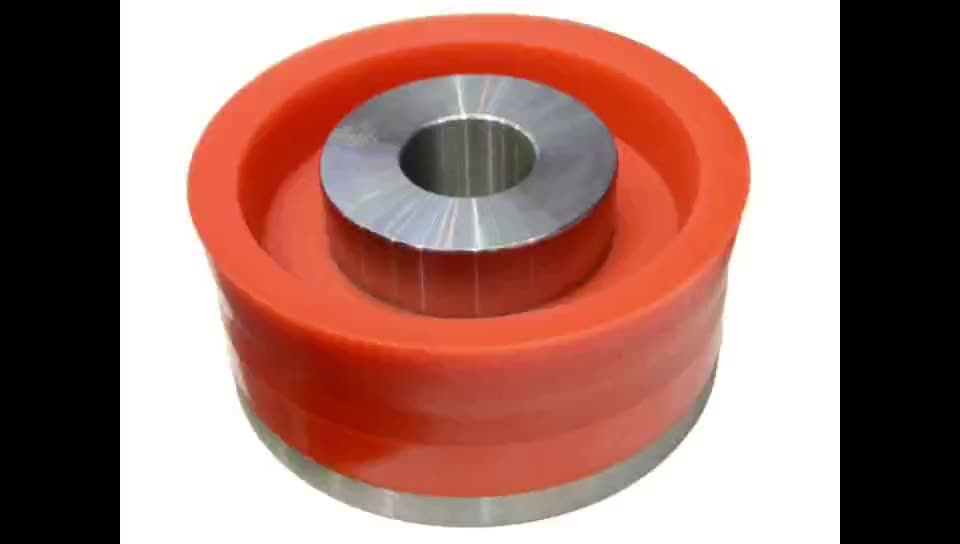
Over time mud pump components wear to the point failure. Pump pistons(swabs), liners, valves and valve seats are all necessary components for generating stable pressure. These are the moving parts on the fluid side of the pump and the most frequent point of failure. Another possible culprit but less common is an inadequately charged pulsation dampener. Deteriorating rubber hoses anywhere in the fluid path, from the mud pump to the saver sub, such as a kelly-hose, can cause an occasional pressure oscillation.
If I could change one thing about today’s directional drilling industry, it would be eliminating the term “pump noise”. The misleading term alone has caused confusion for countless people working on a drilling rig. On the other hand, I’m happy to have learned these lessons the hard way because they seem engrained into my memory. As technology improves, so does the opportunities for MWD technology companies to provide useful solutions. Solutions to aid MWD service providers to properly isolate or overcome the challenges that lead to decoding issues. As an industry we have come a lot further from when I had started, but there is much left to be desired. I’m happy I can use my experiences by contributing to an organization capable of acknowledging and overcoming these obstacles through the development of new technology.

Mud pump is one of the most critical equipment on the rig; therefore personnel on the rig must have good understanding about it. We’ve tried to find the good training about it but it is very difficult to find until we’ve seen this VDO training and it is a fantastic VDO training about the basic of mud pumps used in the oilfield. Total length of this VDO is about thirteen minutes and it is worth to watch it. You will learn about it so quickly. Additionally, we also add the full detailed transcripts which will acceleate the learning curve of learners.
Powerful mud pumps pick up mud from the suction tank and circulate the mud down hole, out the bit and back to the surface. Although rigs usually have two mud pumps and sometimes three or four, normally they use only one at a time. The others are mainly used as backup just in case one fails. Sometimes however the rig crew may compound the pumps, that is, they may use three or four pumps at the same time to move large volumes of mud when required.
Rigs use one of two types of mud pumps, Triplex pumps or Duplex pumps. Triplex pumps have three pistons that move back-and-forth in liners. Duplex pumps have two pistons move back and forth in liners.
Triplex pumps have many advantages they weight 30% less than a duplex of equal horsepower or kilowatts. The lighter weight parts are easier to handle and therefore easier to maintain. The other advantages include;
• One of the more important advantages of triplex over duplex pumps, is that they can move large volumes of mud at the higher pressure is required for modern deep hole drilling.
Triplex pumps are gradually phasing out duplex units. In a triplex pump, the pistons discharge mud only when they move forward in the liner. Then, when they moved back they draw in mud on the same side of the piston. Because of this, they are also called “single acting.” Single acting triplex pumps, pump mud at a relatively high speeds. Input horsepower ranges from 220 to 2200 or 164 to 1641 kW. Large pumps can pump over 1100 gallons per minute, over 4000 L per minute. Some big pumps have a maximum rated pressure of over 7000 psi over 50,000 kPa with 5 inch/127 mm liners.
Here is a schematic of a triplex pump. It has three pistons each moving in its own liner. It also has three intake valves and three discharge valves. It also has a pulsation dampener in the discharge line.
Look at the piston at left, it has just completed pushing mud out of the liner through the open discharge valve. The piston is at its maximum point of forward travel. The other two pistons are at other positions in their travel and are also pumping mud. But for now, concentrate on the left one to understand how the pump works. The left piston has completed its backstroke drawing in mud through the open intake valve. As the piston moved back it instead of the intake valve off its seat and drew mud in. A strong spring holds the discharge above closed. The left piston has moved forward pushing mud through the now open discharge valve. A strong spring holds the intake valve closed. They left piston has completed its forward stroke they form the length of the liner completely discharging the mud from it. All three pistons work together to keep a continuous flow of mud coming into and out of the pump.
Crewmembers can change the liners and pistons. Not only can they replace worn out ones, they can also install different sizes. Generally they use large liners and pistons when the pump needs to move large volumes of mud at relatively low pressure. They use a small liners and pistons when the pump needs to move smaller volumes of mud at a relatively high pressure.
In a duplex pump, pistons discharge mud on one side of the piston and at the same time, take in mud on the other side. Notice the top piston and the liner. As the piston moves forward, it discharges mud on one side as it draws in mud on the other then as it moves back, it discharges mud on the other side and draws in mud on the side it at had earlier discharge it. Duplex pumps are therefore double acting.
Double acting pumps move more mud on a single stroke than a triplex. However, because of they are double acting they have a seal around the piston rod. This seal keeps them from moving as fast as a triplex. Input horsepower ranges from 190 to 1790 hp or from 142 to 1335 kW. The largest pumps maximum rated working pressure is about 5000 psi, almost 35,000 kPa with 6 inch/152 mm linings.
A mud pump has a fluid end, our end and intake and the discharge valves. The fluid end of the pump contains the pistons with liners which take in or discharge the fluid or mud. The pump pistons draw in mud through the intake valves and push mud out through the discharge valves.
The power end houses the large crankshaft and gear assembly that moves the piston assemblies on the fluid end. Pumps are powered by a pump motor. Large modern diesel/electric rigs use powerful electric motors to drive the pump. Mechanical rigs use chain drives or power bands (belts) from the rig’s engines and compounds to drive the pump.
A pulsation dampener connected to the pump’s discharge line smooths out surges created by the pistons as they discharge mud. This is a standard bladder type dampener. The bladder and the dampener body, separates pressurized nitrogen gas above from mud below. The bladder is made from synthetic rubber and is flexible. When mud discharge pressure presses against the bottom of the bladder, nitrogen pressure above the bladder resists it. This resistance smoothes out the surges of mud leaving the pump.
Here is the latest type of pulsation dampener, it does not have a bladder. It is a sphere about 4 feet or 1.2 m in diameter. It is built into the mud pump’s discharge line. The large chamber is form of mud. It has no moving parts so it does not need maintenance. The mud in the large volume sphere, absorbs this surges of mud leaving the pump.
A suction dampener smooths out the flow of mud entering into the pump. Crewmembers mount it on the triplex mud pump’s suction line. Inside the steel chamber is a air charged rubber bladder or diaphragm. The crew charges of the bladder about 10 to 15 psi/50 to 100 kPa. The suction dampener absorbs surges in the mud pump’s suction line caused by the fast-moving pump pistons. The pistons, constantly starts and stops the mud’s flow through the pump. At the other end of the charging line a suction pumps sends a smooth flow of mud to the pump’s intake. When the smooth flow meets the surging flow, the impact is absorbed by the dampener.
Workers always install a discharge pressure relief valve. They install it on the pump’s discharge side in or near the discharge line. If for some reason too much pressure builds up in the discharge line, perhaps the drill bit or annulus gets plugged, the relief valve opens. That opened above protects the mud pump and system damage from over pressure.
Some rig owners install a suction line relief valve. They install it on top of the suction line near the suction dampener. They mount it on top so that it won’t clog up with mud when the system is shut down. A suction relief valve protects the charging pump and the suction line dampener. A suction relief valve usually has a 2 inch or 50 mm seat opening. The installer normally adjusts it to 70 psi or 500 kPa relieving pressure. If both the suction and the discharged valves failed on the same side of the pump, high back flow or a pressure surge would occur. The high backflow could damage the charging pump or the suction line dampener. The discharge line is a high-pressure line through which the pump moves mud. From the discharge line, the mud goes through the stand pipe and rotary hose to the drill string equipment.

Careless axial and rotational movement of the drillstring can cause formation fracturing or fluid influx, resulting in costly remedial actions. With increasingly complex wellbore geometries and narrow geopressure windows, it is not always obvious for the driller how to estimate accurately the real maneuvering limits of the drawworks and the topdrive, especially under poor downhole conditions. The solution presented in this paper uses continuously updated safeguards applied to the drilling-control system to maintain a downhole pressure within the acceptable limits of the openhole formations. It automatically stops the movement of the drillstring in the case of abnormal hookloads or surface torques. Because automatic actions can be triggered in the case of an unexpected situation, some standard procedures have been fully automated, including friction tests and back reaming.
Numerical models are used to constantly calculate the maximum accelerations and velocities, which can be applied to the drillstring in the current drilling conditions. The resulting envelope of protection is dependent on many factors. Therefore, a proper evaluation of the downhole conditions is of paramount importance for the quality of the calculated safeguards. An automatic calibration of the physical models, on the basis of surface measurements, is at the heart of the system. The calibrated mechanical models are used to determine the limits for abnormal surface torques or hookloads. It is, therefore, possible to take actions automatically in the case of overpull, set-down weight, or high torque.
In 2008, a preliminary version of the system was tested during the drilling of a well in the North Sea. Even though the control algorithms did work well at that time, it was noticed that, in some circumstances, the drilling-control system would not be ready in time for fast-changing drilling conditions. An improved version of the drawworks and topdrive automation system has been tested during the drilling of three North Sea wells in the spring of 2009. In this last version, the response time of the system has been optimal at all times. The drillers involved in the testing of the system have found the system useful and user friendly.

n: an accessory to a fishing tool, placed above it. If the to


 8613371530291