
what pressure do you set pop off on mud pump supplier
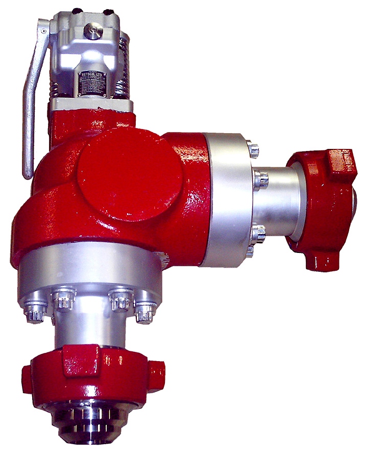
Pressure relief valves are installed on mud pumps in order to prevent an overpressure which could result in a serious damage of the pump and serious or fatal injury to personnel.
The discharge pressure is routed to the closer mud tank, via a 3” XXS line clamped strongly on tank side . Mud is flowing into the mud tank until line bled off, bearing in mind that minimum slope is required to avoid mud settling in pipe ( around 1 inch/meter).
In any cases if you don’t know/ clearly understand how to do it don’t do it, ask your supervisor. Do not start or later on , stop the job if you feel to do so .
Pressure relief valves are set usually to 90% of the maximum working pressure of the liners in use. Read carefully manufacturer chart for pressure setting versus size of liners.
With a low pressure setting, ie, 1000psi, by adjusting the top nylon self lock nut to move on the vertical scale to get the same setting than the scale.
Discharge pressure losses close to the maximum preset pressure.The Pressure relief valves are usually installed on a upper point of the discharge side of the mud pumps.
The pressure relief valve can be reset, if not damaged during the release of pressure. Special care should be taken if no working platform available to access the PRV.

This website is using a security service to protect itself from online attacks. The action you just performed triggered the security solution. There are several actions that could trigger this block including submitting a certain word or phrase, a SQL command or malformed data.

1.1 OBJECTIVE.A key objective of ADC Procedures is to set up a step by step way of handling thejob. It is also an analysis of associated hazards pertaining to the jobs and measures tominimize the risks.This procedure has developed to be applied and discussed before each job listed inthe contents.1.2 SCOPE.This procedure applies to Rig AD-321.3 RESPONSIBILITY.It is the responsibility of the Tool-pusher and Rig Manager to insure all listedoperations are executed in a safe and efficient manner. It is their responsibility toconduct a Pre-job Safety Meeting and discuss and review the related JSA, prior tostarting each operation.Tool-pusher is responsible to ensure that each work permit has its dedicated JSAattached to.JSA to be reviewed and updated at least annually or When equipment is modified When processes are changed When material are changed When changing people/contractors When there is an accident or near miss.The Rig Sup. is accountable for keeping this document up-to date.The JSA date and the crew should be same as Work Permit date and crew.
Table of ContentsTASK ANALYSISIs Procedure relevant for the operation?What can interfere with the operation (Simops)?Who is going to be in charge, position?Who is giving instructions/signals, who replace him?How many people are required to do the job?-
Do you need a PTW/ Isolation (lockout, Tag out)?What is the PPE required?What tools/equipment do you need?Do you need a third party, crane, and forklift?Who else needs to know what you are doing?Do you need to barrier off the area?What are the safest access/escape routes?-
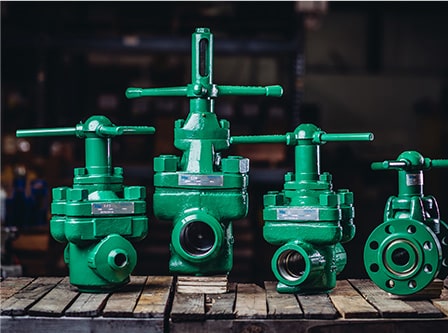
Pressure relief valves are installed on mud pumps in order to prevent an overpressurewhich could result in a serious damage of the pump and serious or fatal injury topersonnel.The discharge pressure is routed to the closer mud tank, via a 2 line minimum clamped allthe way along. Mud is flowing into the mud tank until 0 pressure in the line.Read carefully manufacturer instructions regarding setting, handling, refurbishing of suchequipment.In any cases if you dont know/ understand how to do it dont do it, ask your supervisor.1) Pressure relief valves are set usually to 90% of the maximum working pressure ofthe liners in use. Read carefully manufacturer chart for pressure setting versus sizeof liners.2) The most commonly used pressure relief valve is RETSCO, 500 and 750, whichstands for mud pumps maximum working pressure 5000psi and mud pumps7500psi.3) Prior to installing a pressure relief valve it needs to be tested on a bench.
nut to move on the vertical scale. If the pop off pressure matches the setting, then screw to the pressurerequired on the mud pump (check liner chart) and test again.
When the pressure test has been successful, put a tag on the pressure relief valve, whereit is mentioned:-The date of the test.-The pressure of the test.-If the pressure relief valve was reconditioned.Store it properly away from dust and adverse weather.
1) When/if the pressure relief valve activates due to: I_Bop kept closed and pump started. Build up pressure close to the maximum preset pressure.The pressure relief valve can be reset, if not damaged during the release of pressure.The Pressure relief valves are usually installed on a upper point of the discharge side ofthe mud pumps.Special care should be taken if no working platform available to access the PRV.A safety harness may be necessary in some places.1) Pull round button toward you.2) Pull handle towards you to reset / reposition the knuckle joint inside.3) The handle should have a hard point then come freely.4) If you cannot exert enough force due to position a 1 ID pipe can beused to pull the handle. DO NOT FORCE on the handle if nothingmoves, that means that the discharge piston inside is jammed.
7) Replace PRV by the one ready tested in the store.8) Restore the power on the mud pump.9) Start the pump slowly; check on the discharge pipe above the mudtanks if there are no leaks.10)If everything ok, close work permit, recondition worn pressure reliefvalve, with original parts, pressure test it and store it with a tag asmentioned earlier.

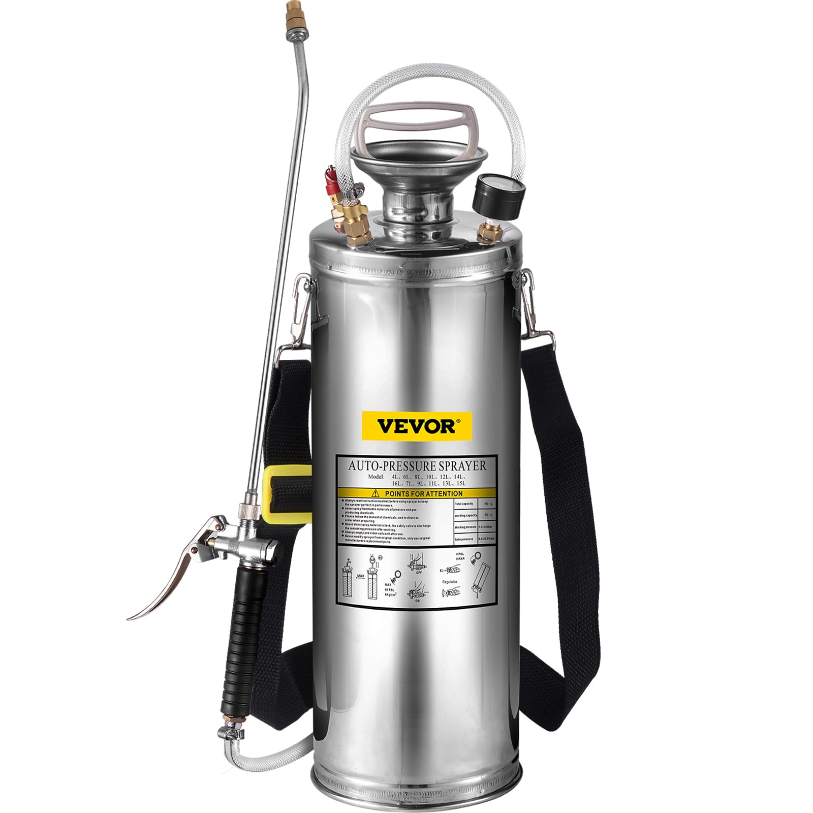
This stainless steel pop-off valve is designed as a secondary pressure relief and should be used with a primary pressure regulating valve. It is set approx 200 PSI above the primary valve and will only go into by-pass should the primary valve fail.

The invention related to drilling fluid or “mud” systems; to relief valves for such systems; and to apparatus, systems and methods for relieving fluid pressure in pressurized devices or systems.
In certain typical wellbore drilling situations using a drilling rig, drilling fluid or “mud” is pumped by a pumping system with one or more “mud” pumps (e.g. some systems have a triplex mud pump). The mud pump system delivers a large volume of mud flow under pressure for operations of the drilling rig. The mud is delivered to the drill stem to flow down the string of drill pipe and out through the drill bit appended to the lower end of the drill stem. It flows through the drill bit. The flow of mud cools the drill bit and reduces the temperature so that it lasts longer. Also, in certain situations, the mud flow is jetted out through a set of openings in the drill bit so that the mud hydraulically washes away the face of the well borehole if it is formed of soft materials. In addition, it washes away debris, rock chips and cuttings which are generated as the drill bit advances. Then, the mud flow returns to the surface in an annular space on the outside of the drill stem and on the interior of the open hole formed by the drilling process. While portions of the borehole may be cased from the surface, is of sufficient velocity that the mud is returned to the surface so that debris, chips and cuttings which are heavier than the mud are moved to the surface. This requires a substantial flow velocity. The cooling necessary also requires a substantial velocity. A relatively high volume of mud is needed to achieve these flow velocities. Typical mud pump systems can deliver 500 to 1,000 gallons per minute through the drill stem. The flow of mud must be delivered under control. The mud pump system can be required to deliver mud flow at 1,000 psi and higher. The wellhead pressures at the pump must be much higher if there is substantial flow pressure resistance along the flow path. The pump therefore is often operated at a very high pressure. The drill stem in a deep well is an impediment to flow, thereby resulting in higher back pressures. The impediment to flow is overcome by applying greater pressures at the surface. In this regard, the mud pump system can typically be operated at pressures as high as 5,000 psi output. Because of the great variety of circumstances in which the drilling rig may be used, the output pressure of the mud pump may vary widely. In one aspect, the mud pump output pressure varies with the change in pump speed. Mud pumps can operate with pressure peaks that can be excursions as great as 200 or 300 psi on top of the prevailing baseline pressure. Thus mud pump output pressure can vary significantly.
The prior art discloses a variety of mud systems, relief valves and regulators, and systems to control and stabilize the pressure downstream of mud pump systems; see, for example, and not by way of limitation, U.S. Pat. Nos. 5,063,776; 5,616,009; 5,975,129; 7,055,623; 5,715,861; 4,638,978; and in U.S. application Ser. No. 11/098,166 filed Apr. 4, 2005 (co-owned with the present invention), all incorporated fully herein for all purposes. In many prior art systems, a mud pump output manifold is input to a pressure relief valve which is operated so that the output pressure is controlled to a desired level, thus allowing a mud pump system to operate with a controlled pressure level to insure that the pressure experienced down hole at the drill bit and in the formations penetrated by the drill bit is regulated and to protect the mud pump system itself.
Various operations involve the use of pressurized systems and/or devices. For example, many different components used in the petroleum drilling and production industries, such as fluid pumps and mud pumps, are used in pressurized systems and subject to potentially significant internal fluid pressures. It is often desirable or necessary to relieve these systems and devices from excessive pressure to prevent equipment damage and failure, personal injury or for other reasons. To assist in relieving undesirable fluid pressure in pressurized systems and devices, pressure relief technology is commonly used.
Currently available versions of pressure relief valves, systems and methods have various disadvantages. For example, many pressure relief valves wear and fail quickly due to high pressure fluid passing therethrough. For another example, various versions of pressure relief valves are large and bulky and require extensive space for operation. For still another example, many pressure relief valves are difficult to disassemble for servicing and maintenance. For an even further example, some pressure relief valves throttle between open and closed positions during operation, which is undesirable in many applications. For still another example, some pressure relief valves are purely mechanical in operation, which may contribute to inaccurate valve operation and overall poor or erratic performance. There are yet other potential disadvantages of presently available pressure relief valves, systems and methods. It should be understood, however, that each embodiment of the present invention and each claim of this patent does not necessarily address or solve every, or any particular, disadvantage of the existing technology.
Thus, there remains a need for pressure relief valve assemblies, systems and methods having one or more of the following attributes, capabilities or features: may be easily disassembled and reassembled; is easy to inspect and service, adjust and/or repair in the field; allows for the repair and replacement of internal valve components without removing the valve body from the line or equipment to which it is attached; has reduced likelihood of damage to internal valve components when discharging fluids; is not difficult to manufacture; includes a valve that is easily opened to allow access for inspection or removal of internal components; includes a valve having an angle-body configuration and/or a fluid flow path with approximately a ninety degree turn; includes a valve having a “flow-to-close” and/or a “fail-to-open” arrangement; includes a valve that opens rapidly and resets easily; includes a snap or pop acting valve; includes a valve having increased longevity; includes a valve that does not throttle between open and closed positions so that when the fluid pressure in the pressurized device is too high, the valve stays fully open until closed; includes a valve actuator that is integral to the valve; includes a reciprocating valve actuator stem or piston that does not protrude from the valve assembly; includes a valve actuator that is electronically controllable; includes an actuator piston engaged with and moveable on the same axis as the valve piston; includes an actuator piston actuated based upon the actual measured pressure of fluid in the pressurized device or system; includes a solenoid valve useful to assist in controlling movement of an actuator piston; includes a valve piston and/or actuator piston that is mechanically-biased in one direction; includes a valve piston and/or actuator piston that is controllably movable in one direction by fluid pressure; includes a valve piston and/or actuator piston that is internally sealed without metal seating; or any combination thereof. BRIEF SUMMARY OF THE PRESENT INVENTION
The present invention, in certain embodiments, discloses pressure relief valve assemblies useful for relieving fluid pressure in a pressurized device (e.g., but not limited to, mud pump systems with at least one mud pump), the pressure relief valve assemblies having: a valve body with an inlet passageway in fluid communication with an outlet passageway; a valve member within the valve body for selectively controlling fluid flow from the inlet passageway to the outlet passageway, the valve member having a first end and a second end, the outlet passageway having an entrance end and an exit end; the first end of the valve member movable into the outlet passageway to prevent fluid flow from the inlet passageway through the outlet passageway; a wear member around a portion of the entrance end of the outlet passageway; the wear member having an interior surface; the valve member movable within and sealingly contacting the interior surface of the wear member; the outlet passageway having a length, the wear member extending into the outlet passageway a distance less than the length of the outlet passageway; the valve body having an interiorly threaded portion at the entrance of the outlet passageway; the wear member having an exteriorly threaded portion; and the wear member releasably secured to the valve body by threaded engagement of the wear member"s exteriorly threaded portion with the valve body"s interiorly threaded portion.
Various embodiments of the present invention involve a pressure relief valve assembly useful for relieving fluid pressure in a pressurized device. The pressure relief valve assembly, in certain aspects, includes an angle-body valve having a valve piston disposed therein and being movable between at least one closed position and at least one open position. The closed position of the valve piston prevents fluid flow through the valve from the pressurized device and the open position allows fluid flow through the valve from the pressurized device.
An actuator according to certain aspects of the present invention is capable of moving the valve piston between closed and opened positions. The actuator includes an actuator piston that is fluid-powered in at least one direction. When the actuator piston is fluid-powered in only one direction, it is mechanically-biased in the opposite direction. The actuator piston is connected with, and movable along the same axis as, the valve piston. The actuator piston is moveable between at least one extended position and at least one retracted position. The valve piston is in a closed position when the actuator piston is in an extended position and the valve piston is in an open position when the actuator piston is in a retracted position. A remotely-operated directional control valve is associated with the actuator and useful for directing fluid power to allow the actuator piston to move from an extended position to a retracted position, causing the valve piston to move from a closed position to an open position.
At least one electronic pressure measuring device is separate from and associated with certain embodiments of the remotely-operated directional control valve and monitors pressure within the pressurized device. The position of the remotely-operated directional control valve is varied based upon power supplied to the control valve that is based upon at least one reading taken by the electronic pressure measuring device.
In some embodiments, a pressure relief valve assembly useful for relieving fluid pressure in a pressurized device includes an unintelligent angle-body valve having a flow-to-close arrangement. The valve includes a valve piston capable of moving between open and closed positions. The valve piston in the open position allows venting of fluid from the pressurized device through the valve. Movement of the valve piston into an open position does not depend upon internal fluid pressure within the unintelligent angle-body valve. At least one electronic pressure measuring device is capable of monitoring pressure within the pressurized device. An electronic controller is capable of causing the opening and closing of the valve piston based upon pressure readings of the electronic pressure measuring device.
Accordingly, the present invention includes features and advantages which are believed to enable it to advance pressure relief valve technology. Characteristics and advantages of the present invention described above and additional features and benefits will be readily apparent to those skilled in the art upon consideration of the following detailed description of preferred embodiments and referring to the accompanying drawings.
Certain embodiments of this invention are not limited to any particular individual feature disclosed here, but include combinations of them distinguished from the prior art in their structures, functions, and/or results achieved. Features of the invention have been broadly described so that the detailed descriptions that follow may be better understood, and in order that the contributions of this invention to the arts may be better appreciated. There are, of course, additional aspects of the invention described below and which may be included in the subject matter of the claims to this invention. Those skilled in the art who have the benefit of this invention, its teachings, and suggestions will appreciate that the conceptions of this disclosure may be used as a creative basis for designing other structures, methods and systems for carrying out and practicing the present invention. The claims of this invention are to be read to include any legally equivalent devices or methods which do not depart from the spirit and scope of the present invention.
What follows are some of, but not all, the objects of this invention. In addition to the specific objects stated below for at least certain preferred embodiments of the invention, there are other objects and purposes which will be readily apparent to one of skill in this art who has the benefit of this invention"s teachings and disclosures. It is, therefore, an object of at least certain preferred embodiments of the present invention to provide:
The present invention recognizes and addresses the problems and needs in this area and provides a solution to those problems and a satisfactory meeting of those needs in its various possible embodiments and equivalents thereof. To one of skill in this art who has the benefits of this invention"s realizations, teachings, disclosures, and suggestions, other purposes and advantages will be appreciated from the following description of certain preferred embodiments, given for the purpose of disclosure, when taken in conjunction with the accompanying drawings. The detail in these descriptions is not intended to thwart this patent"s object to claim this invention no matter how others may later attempt to disguise it by variations in form, changes, or additions of further improvements.
The Abstract that is part hereof is to enable the U.S. Patent and Trademark Office and the public generally, and scientists, engineers, researchers, and practitioners in the art who are not familiar with patent terms or legal terms of phraseology to determine quickly from a cursory inspection or review the nature and general area of the disclosure of this invention. The Abstract is neither intended to define the invention, which is done by the claims, nor is it intended to be limiting of the scope of the invention in any way.
It will be understood that the various embodiments of the present invention may include one, some, or all of the disclosed, described, and/or enumerated improvements and/or technical advantages and/or elements in claims to this invention. BRIEF DESCRIPTION OF THE SEVERAL VIEWS OF THE DRAWINGS
Presently preferred embodiments of the invention are shown in the above-identified figures and described in detail below. It should be understood that the appended drawings and description herein are of preferred embodiments and are not intended to limit the invention or the appended claims. On the contrary, the intention is to cover all modifications, equivalents and alternatives falling within the spirit and scope of the invention as defined by the appended claims. In showing and describing the preferred embodiments, like or identical reference numerals are used to identify common or similar elements. The figures are not necessarily to scale and certain features and certain views of the figures may be shown exaggerated in scale or in schematic in the interest of clarity and conciseness.
As used herein and throughout all the various portions (and headings) of this patent, the terms “invention”, “present invention” and variations thereof mean one or more embodiment, and are not intended to mean the claimed invention of any particular appended claim(s) or all of the appended claims. Accordingly, the subject or topic of each such reference is not automatically or necessarily part of, or required by, any particular claim(s) merely because of such reference. DETAILED DESCRIPTION OF THE INVENTION
Presently preferred embodiments of the invention are shown in the above-identified figures and described in detail below. It should be understood that the appended drawings and description herein are of preferred embodiments and are not intended to limit the invention or the appended claims. On the contrary, the intention is to cover all modifications, equivalents and alternatives falling within the spirit and scope of the invention as defined by the appended claims. In showing and describing the preferred embodiments, like or identical reference numerals are used to identify common or similar elements. The figures are not necessarily to scale and certain features and certain views of the figures may be shown exaggerated in scale or in schematic in the interest of clarity and conciseness.
As used herein and throughout all the various portions (and headings) of this patent, the terms “invention”, “present invention” and variations thereof mean one or more embodiment, and are not intended to mean the claimed invention of any particular appended claim(s) or all of the appended claims. Accordingly, the subject or topic of each such reference is not automatically or necessarily part of, or required by, any particular claim(s) merely because of such reference.
Referring to FIG. 1, a system S according to the present invention includes a mud system M with mud pits 28 for containing and storing drilling fluid; mud pumps 16 for pumping the drilling fluid to drillstring 18 and back to the mud pits 28; and a relief valve 8 according to the present invention for relieving pressure in the system. The drilling fluid or “mud” flows down the drill string 18 and then up in an annulus 20 between casing 22 and the drill string 18 to a bell nipple 24. The mud then flows in a return line 26 to the mud pits 18.
Initially mud flows into the valve 8 through a line 21 that is in communication with the line 19. A pressure sensor 23 senses a signal indicative of the pressure in the line 19, via the line 21, to a control system 14 which controls operation of the valve 8 and controls an air supply 12 which provides air under pressure to maintain the valve 8 closed until a pre-selected mud pressure is exceeded. When the mud pressure exceeds the pre-selected pressure, the valve 10 opens and the mud that was previously flowing to the drill stem 18 flows through the inlet 13 of the valve 8 and exits through an outlet 15 into an exit line 17. When pressure in the line 19 again falls below the pre-selected pressure, the control system 14 signals the air supply 12 to close the valve 8 (as will be described in more detail for certain embodiments described below).
FIG. 2 shows schematically the mud flow path for the system M. As shown in FIG. 2, the system M (like numerals indicate like parts) includes a degasser 25 which reduces the gas content of the mud. In certain aspects, the control system (“CONTROLLER”) includes an automatic reset function and also permits manual resetting (“ReSet,” FIG. 2), e.g. to re-close the valve after it has relieved pressure; and/or the possibility of two settings (“Hi,” “Low,” FIG. 2) corresponding to two different pressure setpoints (e.g. a high setting, e.g. 7500 psi, at which the valve opens for relief and a low setting, e.g. below 400 psi). The valve is operable by manually pressing an “Operate” button. The controller can be a computerized system and/or PLC appropriately programmed.
Referring now to FIGS. 3A-3C, a relief valve 100 (one embodiment of the relief valve 8, FIG. 1) includes a valve 120 and an actuator 160. In the embodiment shown, the valve 120 is an angle-body, two-way valve that includes a valve body 126 having intersecting first and second passageways 130, 140. The first passageway 130 is in fluid communication with a pressurized device (not shown) (e.g. a mud pump or pumps) and allows fluid flow (arrow 131) into the valve body 126 from the pressurized device. The second passageway 140 extends to an exit port 144, allowing the exhaust (arrow 146) of fluid from the valve body 126. In an “angle-body” valve, the axis of the first passageway 130 is not concentric or coaxial with, but is approximately in the same plane as, the axis of the second passageway 140. Nuts 132 aare used on valve body studs 132 b; and nuts 142 aare used on valve body studs 142 b.
A valve piston 148 is disposed at least partially within the second passageway 140 and serves to selectively control the flow of fluid from the first passageway 130 into the second passageway 140. The valve piston 148 is movable between “open” and “closed” positions relative to the first passageway 130. In a “closed” position, such as shown in FIGS. 3A and 3B, the exemplary valve piston 148 blocks the first passageway 130, preventing fluid flow from the first passageway 130 into the second passageway 140. When the valve piston 148 is in an “open” position, the first and second passageways 130, 140 are in fluid communication, allowing the flow of fluid from the first passageway 130 (and pressurized device) into the second passageway 140 (and out the exit port 144). The valve 120 of the illustrated embodiment has a “flow-to-close” arrangement in which fluid flows through the second passageway 140 in the same direction as the movement made by the valve piston 148 going to its closed position.
The valve piston 148 has a removable cap 153 which is threadedly connected to an end of the valve piston 148. Optionally the cap 153 has an inclined or bevelled end surface 151 with holes 154 for facilitating piston installation. An exterior surface 157 of the cap 153 abuts an interior surface 121 of a seal insert 128.
The seal insert 128 (or, in one aspect a “wear member”) is threadedly and removably secured in the body 126. In one particular aspect, the seal insert 128 is made of Inconel material due to the high wear area at the beginning of the passageway 140 at which the seal insert 128 is located. In certain aspects, the seal insert"s length is considerably less than the length of the passageway 140 and, in one particular aspect, less than half said length.
The valve piston 148 has an edge 147. The seal insert 128 is sized with a sufficient length to encounter the initial highly abrasive flow of fluid at high speed from the passageway 130 to the passageway 140. Once this fluid exits the seal insert 128 it slows sufficiently so that the remainder of the interior of the passageway 140 (not protected by the seal insert 128) is not seriously worn or damaged. A seal 149 seals a valve-piston-148/actuator-housing-164 interface.
By unbolting the actuator 160 (by removing bolts 169) from the valve body 126, and removing valve piston 148 with its cap 153 from the passageway 140, the seal insert 128 can be removed from the valve body 126 for repair or replacement.
A seal 122 in a recess 157 seals a seal-insert 128/valve-body-126 interface. Holes 123 facilitate installation of the seal insert 128. Holes 152 in a cap 139 facilitate installation of the cap 139.
The actuator housing 164 has a central cavity 170 within which an actuator piston 174 is moveable. The exemplary central cavity 170 is aligned with the second passageway 140 of the valve body 26. The actuator piston 174 connects to the valve piston 148 and moves it between open and closed positions. In the example shown, an actuator stem 180 connects the actuator piston 174 with a valve stem 150 extending from the valve piston 148, all of which move on the same axis. The cap 139 is threadedly secured around the valve stem 150.
The actuator stem 180 and valve stem 150 are releasably connected together with a releasable latch pin 156 to allow quick disconnection and replacement of the valve piston 148 without disturbing the actuator 160. The illustrated latch pin 156 extends through an opening 158 in the actuator housing 164 to allow for unencumbered movement of the latch pin 156 concurrent with reciprocation of the stems 150, 180.
The actuator piston 174 may be actuated in any desired manner. In the embodiment shown in FIG. 3A, the actuator piston 174 is single acting, being fluid-powered in one direction (e.g. by pneumatic or hydraulic pressure) and mechanically-biased in the opposite direction. In one aspect when the pressurized device is a mud pump or pumps, the power fluid is air, e.g. air supplied by a rig air supply. For example, air or pneumatic pressure may be provided from an external source (not shown) into an outer portion 172 of the central cavity 170 of the actuator housing 164 to act upon an outer side 178 of the actuator piston 174 and move and hold the actuator piston 174 in an “extended” position and the valve piston 148 in a closed position (e.g. FIG. 3A). In the illustrated embodiment, in one normal operating state of the valve assembly 100 has the actuator piston 174 in an extended position and the valve piston 148 in a closed position.
The mechanical-biasing force on the actuator piston 174 (and effectively on the valve piston 148), when included, may be provided in any suitable manner. For example, one or more spring element or spring-like devices may be used to provide the sufficient biasing forces on the actuator piston 174 and move and hold the actuator piston 174 in a retracted position and the valve piston 148 in an open position, regardless of the system pressure or fluid pressure in the valve assembly 100.
In the embodiment of FIG. 3A, for example, outer and inner nested compression springs 184, 186, respectively, are shown disposed around the actuator stem 180 in the central cavity 170. The springs 184, 186 act on the inner side 176 of the actuator piston 174 to move and hold the actuator piston 174 in a “retracted” position (and the valve piston 148 in an open position). The use of dual nested springs may be included, for example, to provide adequate biasing forces in the small area of the central cavity 170 sufficient to move the actuator piston 174 and the valve piston 148. In the embodiment shown, the springs 184, 186 provide sufficient biasing force to overcome multiple sealing engagements, such as at the seals 134 and 149. However, the present invention is not limited to fluid-powering in only one direction, the use of mechanical-biasing forces or the use of one or more spring element to provide mechanical-biasing force on the actuator piston and/or the valve piston.
If desired, one or more devices may be included for cushioning any contact of the actuator piston 174 with other components during its movement. For example, in FIG. 3A, an elastomeric cushion ring 181 is disposed in an actuator end cap 182 to cushion contact of the actuator piston 174 with the end cap 182.
In another independent aspect of the invention, the actuator 160 may be controlled to move the valve piston 148 between open and closed positions in any desired manner. For example, referring to FIG. 3A, the actuator 160 may be controlled based upon the fluid pressure within, or coming from, the pressurized device (not shown), referred to herein and throughout this patent as the “relevant pressure.” Such a control scheme is referred to herein and throughout this patent as a “pressure-based” system. For example, when the valve assembly 100 of FIG. 3A is used with a fluid pump, the relevant pressure may be the upstream pressure of fluid flow into the first passageway 130 of the valve body 126 from the fluid pump. When the relevant pressure is at an acceptable or desirable value (or range), the actuator 160 retains the valve piston 148 in a closed position, not relieving pressure from the fluid pump. If the relevant pressure increases to a certain level or range, the actuator 160 is triggered to move the valve piston 148 to an open position, allowing fluid pressure relief for the fluid pump. After a certain period or, alternately, when the relevant pressure returns to a certain level or range, the actuator 160 of this example is adjusted to allow the valve piston 148 to move back to a closed position, and so on.
Any suitable components and techniques may be used in a pressure-based system. For example, a directional control valve may be used to control fluid power acting upon the actuator piston to allow it to move from an extended position to a retracted position. For example, referring to FIG. 3A, the directional control valve is a three-way, two position solenoid valve (not shown) used to control pneumatic or other fluid pressure in the outer portion 172 of the central cavity 170 of the actuator housing 164. The exemplary solenoid valve is connected with the actuator end cap 182 and actuated based upon the relevant pressure of the pressurize device (not shown). In the embodiment shown, the solenoid valve is maintained in a fluid-to-cylinder/exhaust-blocked position that allows pressurized fluid to the outer portion 172 of the outer cavity 170 through at least one port 166 to act upon the outer side 178 of the actuator piston 174 and move or retain the actuator piston 174 in an extended position. For example, air pressure in the outer portion 172 of the central cavity 170 may, in certain applications, be maintained at approximately 90 psig.
If the relevant pressure reaches a certain value (or range), the solenoid valve is actuated to move to a supply-fluid-blocked/cylinder-exhausted position, blocking or preventing pressurized fluid from acting upon the outer side 178 of the actuator piston 174 and allowing pressurized fluid from the outer portion 172 of the central cavity 170 to be exhausted from the actuator 160. This permits the actuator piston 174 to move into a retracted position, opening the valve piston 148. When the relevant pressure returns to a desired level or range, the solenoid valve is actuated to allow fluid back into the outer portion 172 of the central cavity 170 of the actuator 160. In the embodiment shown, the mechanical forces on the actuator piston 174 are overcome and the actuator piston 174 returns to an extended position, closing the valve piston 148.
In yet another independent aspect of the invention, the actuator 160 may be electronically controlled by an electronic control device or system, if desired, e.g. the “CONTROLLER” of FIG. 2 which may be any suitable control system, computerized system, and/or PLC, on-site or remote. In conjunction with the embodiment of FIG. 3A, a control valve according to the present invention is on-site or remotely-operated by a programmable logic controller (PLC) that receives relevant pressure readings from one or more electronic pressure measuring devices (e.g. “SENSOR,” FIG. 2). For example, the electronic pressure measuring device may be a pressure transducer that accurately measures, detects or reads fluid pressure in the pressurized device or the upstream pressure of fluid within, or proximate to, the first passageway of the valve body. If desired, the electronic pressure measuring device may either continuously or intermittently monitor such pressure. The position of the exemplary remotely-operated directional control valve is varied based upon electrical, mechanical, fluid power or a combination thereof supplied to it based upon at least one reading taken by the electronic pressure measuring device.
In operation of the illustrated embodiment used in conjunction with the valve assembly 100 of FIG. 3A, the PLC is powered by any suitable power supply and receives input indicating the relevant pressure from the electronic pressure measuring device. The PLC compares the received fluid pressure value(s) with one or more pre-programmed set point values or ranges (the “set point”). If the relevant pressure reaches the set point, the PLC closes a relay (not shown), providing electric power to the directional control valve, causing it to function to temporarily block the fluid supply, such as from a rig air source, into the central cavity outer portion and allow the fluid in the outer portion to exhaust out of the actuator through the directional control valve. The actuator piston is then allowed to move into a retracted position, opening the valve piston.
Thereafter, when the PLC detects that the relevant pressure has returned to a desired value/range, or based upon some other criteria, the PLC resets, or opens, the relay, reducing or eliminating power to the directional control valve. This causes the valve to function to allow fluid back into the outer portion of the central cavity, which moves the actuator piston back to an extended position. If desired, multiple set points may be used. In one example, a 0-8,000 p.s.i. pressure relief valve assembly 100 snaps open quickly (with minimal throttling) based upon a signal from a pressure transducer at a degree of accuracy of with 20% (±16 psig) of the set point pressure value. However, the present invention is not limited to such electronic control or the control components and techniques described above.
Referring initially to FIG. 1, an embodiment of a pressure relief valve assembly 10 in accordance with the present invention is shown. The pressure relief valve assembly 10 is capable of relieving fluid pressure in a device or system which is desired to be relieved of pressure (referred to herein and throughout this patent as a “pressurized device”). As used herein and throughout this patent, the term “fluid” means one or more gas, liquid, or a combination thereof, and may, if desired and suitable, also include material or particles, or slurries thereof. The pressurized device may, for example, include a triplex or duplex mud pump that may experience overpressure situations. In various embodiments, the valve assemblies of the present invention relieves such overpressure situations. However, the present invention is not limited to such use with mud pumps.
Preferred embodiments of the present invention thus offer advantages over the prior art and are well adapted to carry out one or more of the objects of the invention. However, the present invention does not require each of the components and actions described above. Any one or more of the above components, features and processes may be employed in any suitable configuration without inclusion of other such components, features and processes. Further, the present invention is not limited to the above-described embodiments and methods of operation. Additional features, capabilities, components, functions, methods, uses and applications may be included.
The methods described above and any other methods which may fall within the scope of any of the appended claims can be performed in any desired suitable order and are not necessarily limited to the sequence described herein or as may be listed in any of the appended claims. Moreover, the methods of the present invention do not require use of the particular components or embodiments shown and described in the present specification, but are equally applicable with any other suitable structure, form and configuration of components.
Accordingly, while preferred embodiments of this invention have been shown and described, many variations, modifications and/or changes of the system, apparatus and methods of the present invention, such as in the components, details of construction and operation, arrangement of parts and/or methods of use, are possible, contemplated by the patentee, within the scope of the appended claims, and may be made and used by one of ordinary skill in the art without departing from the spirit or teachings of the invention and scope of appended claims. Thus, all matter herein set forth or shown in the accompanying drawings should be interpreted as illustrative and not limiting, and the scope of the invention and the appended claims is not limited to the embodiments described and shown herein.
The present invention, therefore, in some, but not necessarily all embodiments, provides pressure relief valve assemblies useful for relieving fluid pressure in a pressurized device, the assemblies having: a valve body with an inlet passageway in fluid communication with an outlet passageway; a valve member within the valve body for selectively controlling fluid flow from the inlet passageway to the outlet passageway, the valve member having a first end and a second end, the outlet passageway having an entrance end and an exit end; the first end of the valve member movable into the outlet passageway to prevent fluid flow from the inlet passageway through the outlet passageway; a wear member around a portion of the entrance end of the outlet passageway; the wear member having an interior surface, the valve member movable within and sealingly contacting the interior surface of the wear member; the outlet passageway having a length, the wear member extending into the outlet passageway a distance less than the length of the outlet passageway; the valve body having an interiorly threaded portion at the entrance of the outlet passageway; the wear member having an exteriorly threaded portion, and the wear member releasably secured to the valve body by threaded engagement of the wear member"s exteriorly threaded portion with the valve body"s interiorly threaded portion. Such assemblies may have one or some (in any possible combination) of the following: wherein the wear member has a length which is less than half the length of the outlet passageway; an actuator connected to the second end of the valve member for selectively actuating the pressure relief valve assembly; the actuator including an actuator housing with a flange, the flange having bolt holes therethrough, the flange releasably bolted to the valve body; a first cap at the first end of the valve member, and a second cap at the second end of the valve member; a bore through the valve body, the wear member accessible through the bore for installation and removal thereof; a bore through the valve body, the wear member accessible through the bore for installation and removal thereof, the actuator having an actuator housing bolted to the valve body, part of the actuator housing projecting into the bore, the bore accessible when the actuator housing is unbolted from the valve body and the actuator is removed therefrom; a controller for selectively moving the valve member; the controller includes an automatic reset function to automatically close the pressure relief valve assembly following the pressure relief valve assembly acting to relieve pressure in a pressurized device; the controller programmable to reset at one of a plurality of different measured pressures at the inlet passageway; the controller able to reset the pressure relief valve assembly automatically; the pressure relief valve assembly is resettable manually; the fluid pressure is pressure of drilling fluid and the pressurized device includes apparatus for the flow of drilling fluid under pressure; the pressurized device includes at least one mud pump; wherein the wear member is made of INCONEL material; and/or the actuator is initially acted upon by fluid under pressure to maintain the valve member in a valve-closed position.
The present invention, therefore, provides pressure relief valve assemblies useful for relieving fluid pressure in a pressurized device, the assemblies having: a valve body with an inlet passageway in fluid communication with an outlet passageway; a valve member within the valve body for selectively controlling fluid flow from the inlet passageway to the outlet passageway, the valve member having a first end and a second end, the outlet passageway having an entrance end and an exit end; the first end of the valve member movable into the outlet passageway to prevent fluid flow from the inlet passageway through the outlet passageway; a wear member around a portion of the entrance end of the outlet passageway; the wear member having an interior surface, the valve member movable within and sealingly contacting the interior surface of the wear member; the outlet passageway having a length, the wear member extending into the outlet passageway a distance less than the length of the outlet passageway; the valve body having an interiorly threaded portion at the entrance of the outlet passageway; the wear member having an exteriorly threaded portion; the wear member releasably secured to the valve body by threaded engagement of the wear member"s exteriorly threaded portion with the valve body"s interiorly threaded portion; wherein the wear member has a length which is less than half the length of the outlet passageway; an actuator connected to the second end of the valve member for selectively actuating the pressure relief valve assembly; a bore through the valve body; the wear member accessible through the bore for installation and removal thereof; the actuator having an actuator housing bolted to the valve body, part of the actuator housing projecting into the bore; and the bore accessible when the actuator housing is unbolted from the valve body and the actuator is removed therefrom.
The present invention, therefore, provides in at least some embodiments, but not necessarily all, pressure relief valve assemblies useful for relieving fluid pressure in a pressurized device, the pressure relief valve assemblies having: a valve body with an inlet passageway in fluid communication with an outlet passageway; a valve member within the valve body for selectively controlling fluid flow from the inlet passageway to the outlet passageway, the valve member having a first end and a second end, the outlet passageway having an entrance end and an exit end; the first end of the valve member movable into the outlet passageway to prevent fluid flow from the inlet passageway through the outlet passageway; a wear member around a portion of the entrance end of the outlet passageway; an actuator connected to the second end of the valve member for selectively actuating the pressure relief valve assembly; wherein the actuator includes an actuator housing with a part, e.g., but not limited to, a flange; the part having bolt holes therethrough; and the part and therefore the housing releasably bolted to the valve body. Such an assembly may have: fluid pressure which is pressure of drilling fluid, and the pressurized device including apparatus for the flow of drilling fluid under pressure; and/or the pressurized device including at least one mud pump.
In conclusion, therefore, it is seen that the present invention and the embodiments disclosed herein and those covered by the appended claims are well adapted to carry out the objectives and obtain the ends set forth. Certain changes can be made in the subject matter without departing from the spirit and the scope of this invention. It is realized that changes are possible within the scope of this invention and it is further intended that each element or step recited in any of the following claims is to be understood as referring to the step literally and/or to all equivalent elements or steps. The following claims are intended to cover the invention as broadly as legally possible in whatever form it may be utilized. The invention claimed herein is new and novel in accordance with 35 U.S.C. § 102 and satisfies the conditions for patentability in § 102. The invention claimed herein is not obvious in accordance with 35 U.S.C. § 103 and satisfies the conditions for patentability in § 103. This specification and the claims that follow are in accordance with all of the requirements of 35 U.S.C. § 112. The inventors may rely on the Doctrine of Equivalents to determine and assess the scope of their invention and of the claims that follow as they may pertain to apparatus not materially departing from, but outside of, the literal scope of the invention as set forth in the following claims. All patents and applications identified herein are incorporated fully herein for all purposes.
Legal status (The legal status is an assumption and is not a legal conclusion. Google has not performed a legal analysis and makes no representation as to the accuracy of the status listed.)
Current Assignee (The listed assignees may be inaccurate. Google has not performed a legal analysis and makes no representation or warranty as to the accuracy of the list.)
Priority date (The priority date is an assumption and is not a legal conclusion. Google has not performed a legal analysis and makes no representation as to the accuracy of the date listed.)
F16—ENGINEERING ELEMENTS AND UNITS; GENERAL MEASURES FOR PRODUCING AND MAINTAINING EFFECTIVE FUNCTIONING OF MACHINES OR INSTALLATIONS; THERMAL INSULATION IN GENERAL
Y—GENERAL TAGGING OF NEW TECHNOLOGICAL DEVELOPMENTS; GENERAL TAGGING OF CROSS-SECTIONAL TECHNOLOGIES SPANNING OVER SEVERAL SECTIONS OF THE IPC; TECHNICAL SUBJECTS COVERED BY FORMER USPC CROSS-REFERENCE ART COLLECTIONS [XRACs] AND DIGESTS
Y—GENERAL TAGGING OF NEW TECHNOLOGICAL DEVELOPMENTS; GENERAL TAGGING OF CROSS-SECTIONAL TECHNOLOGIES SPANNING OVER SEVERAL SECTIONS OF THE IPC; TECHNICAL SUBJECTS COVERED BY FORMER USPC CROSS-REFERENCE ART COLLECTIONS [XRACs] AND DIGESTS
Method and device for preventing a primary relief valve (12) in a mud system (1) from opening at a pressure lower than a nominal opening pressure, and where the mud system (1) includes a mud pump (2), wherein the method includes: - installing an flow restrictor (16) between the mud pump (2) and the primary relief valve (12); and -providing a cavity (20) between the flow restrictor (16) and the primary relief valve (12).
There is provided a method for preventing a primary mud re¬ lief valve from incorrect opening. More precisely there is provided method for preventing a primary relief valve in a mud system from incorrect opening, where the mud system includes a mud pump.
Mud systems, as known from drilling rigs, normally include a mud pump, a pulsation dampener and a relief valve, the latter herein termed "primary relief valve". The main pump is typi¬ cally a triplex pump. This kind of pump delivers a flow rate which is far from constant but fluctuates much because of i) variable piston speed - the pump is crank shaft driven, ii) mud compressibility and iii) valve and fluid inertia. The pulsation dampener is therefore included to smoothen the flow rate and mitigate the resulting pressure fluctuations. The primary relief valve may be of a design known as a "pop-off valve" in the industry, or a rupture disk. Other types of re¬ lief valves are also known.
The primary relief valve is a safety valve that is designed to prevent excessive pressure and possible hazards in the case the pump pressure exceed the certified pressure limit for the system. Normally the so-called trip pressure, at
which the primary relief valve shall switch from a closed to an open state, is set slightly higher that the system pres¬ sure of typically 5000 psi (345 bar) .
It is a well-known problem in the industry that the primary relief valve sometimes trips frequently even though the rec¬ orded pressure levels never reached the nominal trip pressure level .
Tripping of a primary relief valve represents a costly and highly undesired disruption of the drilling process, both because of the time it takes to refit a new rupture disk or to reset a resettable primary relief valve and because the well can be damaged during long periods of no circulation. To lower the risk for primary relief valve tripping one can therefore reduce maximum working pressure to say 80 per cent of the system pressure limit. This is also a costly solution be¬ cause flow rate and pressure is often a limiting factor that can lead to slower drilling and even cause well stability problems. The opposite solution of increasing the nominal trip pressure to compensate for the dynamic effect is also a highly undesirable solution that may lead to damage in other parts of the mud system. It may even be illegal to raise the nominal relief valve pressure to more than a few per cent over the certified system pressure.
According to a first aspect of the invention there is provid¬ ed a method for preventing a primary relief valve in a mud system from opening at a pressure lower than a nominal open-
A field study of above stated problem has revealed that the reason for the tripping of the primary relief valve at a pressure lower than the nominal opening pressure, most likely is relatively large pressure fluctuations in a pop-off line. Despite of the damping action of a pulsation dampener, there are substantial residual pressure fluctuation present in a discharge pipe between the pump and the dampener. The pop-off line itself represents a hydraulic resonator that can signif¬ icantly amplify these residual fluctuations at frequencies close to resonance frequencies. This explanation is supported by special pressure measurements just below the primary re¬ lief valve showing that the peak dynamic pressure can some¬ times exceed 115 per cent of the mean pressure.
These pressure fluctuations can lead to undesired primary re¬ lief valve trips, both because the peak pressure are really higher than seen on the standard pressure sensors, and be¬ cause they can lead to fatigue and lowering of the real trip pressure. This fatigue effect is especially relevant if the primary relief valve is a rupture disk.
It has thus been found that the opening of the primary relief valve is related to pressure variation at higher frequencies, typically in the region of 40Hz. Pressure fluctuations at this frequency has been measured to be up to 40 bars. Such fluctuations are superimposed on the mean pressure and are believed to cause the tripping of the primary relief valve at a pressure lower than the nominal opening pressure.
The high frequency pressure fluctuation components appear to be generated by the mud pumps and are related to the pump valve action. Both mud compressibility and pump valve inertia tend to cause sudden changes in the pump flow rate when the pump discharge valves open and closes. The changes give rise to a pressure pulse that is enhanced at frequencies close to the resonance frequencies of the closed primary relief valve line .
By installing a flow restriction between the mud pump and the primary relief valve in combination with a cavity positioned between the flow restriction and the primary relief valve, these higher frequency pressure fluctuations are dampened. The pressure acting on the primary relief valve is then the mean operating pressure of the mud system. The relation between the size of the flow restrictor and the cavity volume should be calculated according to known principles, or it should be found experimentally by testing different
The flow restrictor may be in the form of a tubing having a diameter much smaller than the so called characteristic di¬ mension of the cavity, say smaller than the cubic root of said cavity, and a length much longer than the diameter of the flow restriction.
Said flow restrictor may be in the form of an opening in a plate where the opening has a diameter much smaller than the characteristic dimension of the cavity.
The method may include placing a second relief valve in par¬ allel with the flow restrictor, preferably with a lower nominal trip pressure than the primary relief valve.
This second relief valve will normally only experience the dynamic pressure difference as it receives the mud pump pres¬ sure on one side and the smoothed pressure at the cavity on the other side.
According to a second aspect of the invention there is pro¬ vided device for preventing a primary relief valve in a mud system from opening at a pressure lower than a nominal opening pressure and where the mud system includes a mud pump, wherein a flow restrictor is positioned between the mud pump and the primary relief valve, and where a cavity is provided between the flow restrictor and the primary relief valve.
In a practical embodiment of the invention, the primary re¬ lief valve, the flow restriction, the second relief valve and the cavity may be produced as one unit that is fairly compact and suitable for installation in a mud system.
The method and device according to the invention render it possible to overcome the long felt problem of incorrect open¬ ing of the primary relief valve of a mud system.
On the drawings the reference number 1 denotes a part of a mud system that includes a mud pump 2 that draws mud from a mud reservoir 4 and discharge the mud via a discharge pipe 6 into a so-called stand pipe 8. A pulsation dampener 10 is connected to the discharge pipe 6. A primary relief valve 12 is connected to the discharge pipe 6 via a so-called pop-off line 14. In this exemplary embodiment, the primary relief valve 12 is a pop-off valve. However, in other embodiments, the primary relief valve 12 may be a rupture disk or another suitable valve.
According to the present invention a flow restriction 16 is provided between the mud pump 2 and the primary relief valve 12, or more precisely between the discharge pipe 6 and the primary relief valve 12.
A second relief valve 18, which may be of a type similar to the primary relief valve 12, is positioned in parallel with the flow restriction 16. A cavity 20 is closed off in the pop-off line 14 between the primary relief valve 12 and the second relief valve 18. The cavity 20 communicates with the discharge pipe 6 through the flow restriction 16.
As stated in the general part of the description, the cavity 20 in relation to the size of the flow restriction 16 should be determined according to well known principles in order to dampen the dynamic frequency pressure at the actual frequen¬ cies .
This done, as the mud pump 2 operates, the high frequency pressure fluctuation components are dampened in the flow re¬ striction 16/cavity 20 dampener system. Thus, the primary relief valve 12 only experiences the average pressure present in the cavity 20.
The second relief valve 18 has the pressure from the mud pump 2 acting on the side facing the discharge pipe 6, while the average pressure is acting on the side of the second relief valve 18 facing the cavity 20. The resultant pressure across the second relief valve 18 equals the dynamic pressure fluc¬ tuations in the discharge line 6, normally with zero mean.
Then, as the flow through the flow restriction 16 is minute compared to that of the primary relief valve 12, the pressure over the second relief valve 18 will equal the full pressure from the mud pump 2. The second relief valve 18 will then al¬ so open if the high average pressure is still present. To en¬ sure tripping of the second relief valve 18, its trip pres¬ sure may preferably be slightly lower than the trip pressure of the primary relief valve 12.
In an alternative embodiment, see fig. 2, the pressure sens¬ ing component of the second relief valve 18 is a rupture disk 22. A flow restriction 16 is incorporated in the rupture disk
22, see fig. 3. Aside from the second relief valve 18 being a rupture disk in this embodiment, rather than a pop-off valve, mud system 1 and its functioning are as previously described.
1. Method for preventing a primary relief valve (12) in a mud system (1) from opening at a pressure substantially lower that a nominal opening pressure, where the mud sys¬ tem (1) includes a mud pump (2) , c h a r a c t e r i z e d i n that the method includes:
i n that said restrictor (16) constitutes a tubing hav¬ ing a diameter much smaller than a characteristic dimension of said cavity (20) and a length much longer than the flow restrictor" s (16) diameter.
i n that said restrictor (16) constitutes an opening in a plate, where the openings diameter much smaller than a characteristic dimension of said cavity (20) .
5. A device for preventing a primary relief valve (12) in a mud system (1) from opening at a pressure lower than a nominal opening pressure and where the mud system (1) in¬ cludes a mud pump (2), c h a r a c t e r i z e d b y that a flow restrictor (16) is positioned between the mud pump (2) and the primary relief valve (12), and that a cavity (20) is provided between the flow restrictor (16) and the primary relief valve (12) . Device according to claim 5, c h a r a c t e r i z e d i n that a second relief valve (18) is placed in paral¬ lel with the flow resistor (16) .
If you run a mud rig, you have probably figured out that the mud pump is the heart of the rig. Without it, drilling stops. Keeping your pump in good shape is key to productivity. There are some tricks I have learned over the years to keeping a pump running well.
First, you need a baseline to know how well your pump is doing. When it’s freshly rebuilt, it will be at the top efficiency. An easy way to establish this efficiency is to pump through an orifice at a known rate with a known fluid. When I rig up, I hook my water truck to my pump and pump through my mixing hopper at idle. My hopper has a ½-inch nozzle in it, so at idle I see about


 8613371530291