
what pressure do you set pop off on mud pump in stock
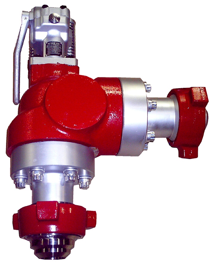
Pressure relief valves are installed on mud pumps in order to prevent an overpressure which could result in a serious damage of the pump and serious or fatal injury to personnel.
The discharge pressure is routed to the closer mud tank, via a 3” XXS line clamped strongly on tank side . Mud is flowing into the mud tank until line bled off, bearing in mind that minimum slope is required to avoid mud settling in pipe ( around 1 inch/meter).
In any cases if you don’t know/ clearly understand how to do it don’t do it, ask your supervisor. Do not start or later on , stop the job if you feel to do so .
Pressure relief valves are set usually to 90% of the maximum working pressure of the liners in use. Read carefully manufacturer chart for pressure setting versus size of liners.
With a low pressure setting, ie, 1000psi, by adjusting the top nylon self lock nut to move on the vertical scale to get the same setting than the scale.
Discharge pressure losses close to the maximum preset pressure.The Pressure relief valves are usually installed on a upper point of the discharge side of the mud pumps.
The pressure relief valve can be reset, if not damaged during the release of pressure. Special care should be taken if no working platform available to access the PRV.

This website is using a security service to protect itself from online attacks. The action you just performed triggered the security solution. There are several actions that could trigger this block including submitting a certain word or phrase, a SQL command or malformed data.

Mud pump is one of the most critical equipment on the rig; therefore personnel on the rig must have good understanding about it. We’ve tried to find the good training about it but it is very difficult to find until we’ve seen this VDO training and it is a fantastic VDO training about the basic of mud pumps used in the oilfield. Total length of this VDO is about thirteen minutes and it is worth to watch it. You will learn about it so quickly. Additionally, we also add the full detailed transcripts which will acceleate the learning curve of learners.
Powerful mud pumps pick up mud from the suction tank and circulate the mud down hole, out the bit and back to the surface. Although rigs usually have two mud pumps and sometimes three or four, normally they use only one at a time. The others are mainly used as backup just in case one fails. Sometimes however the rig crew may compound the pumps, that is, they may use three or four pumps at the same time to move large volumes of mud when required.
Rigs use one of two types of mud pumps, Triplex pumps or Duplex pumps. Triplex pumps have three pistons that move back-and-forth in liners. Duplex pumps have two pistons move back and forth in liners.
Triplex pumps have many advantages they weight 30% less than a duplex of equal horsepower or kilowatts. The lighter weight parts are easier to handle and therefore easier to maintain. The other advantages include;
• One of the more important advantages of triplex over duplex pumps, is that they can move large volumes of mud at the higher pressure is required for modern deep hole drilling.
Triplex pumps are gradually phasing out duplex units. In a triplex pump, the pistons discharge mud only when they move forward in the liner. Then, when they moved back they draw in mud on the same side of the piston. Because of this, they are also called “single acting.” Single acting triplex pumps, pump mud at a relatively high speeds. Input horsepower ranges from 220 to 2200 or 164 to 1641 kW. Large pumps can pump over 1100 gallons per minute, over 4000 L per minute. Some big pumps have a maximum rated pressure of over 7000 psi over 50,000 kPa with 5 inch/127 mm liners.
Here is a schematic of a triplex pump. It has three pistons each moving in its own liner. It also has three intake valves and three discharge valves. It also has a pulsation dampener in the discharge line.
Look at the piston at left, it has just completed pushing mud out of the liner through the open discharge valve. The piston is at its maximum point of forward travel. The other two pistons are at other positions in their travel and are also pumping mud. But for now, concentrate on the left one to understand how the pump works. The left piston has completed its backstroke drawing in mud through the open intake valve. As the piston moved back it instead of the intake valve off its seat and drew mud in. A strong spring holds the discharge above closed. The left piston has moved forward pushing mud through the now open discharge valve. A strong spring holds the intake valve closed. They left piston has completed its forward stroke they form the length of the liner completely discharging the mud from it. All three pistons work together to keep a continuous flow of mud coming into and out of the pump.
Crewmembers can change the liners and pistons. Not only can they replace worn out ones, they can also install different sizes. Generally they use large liners and pistons when the pump needs to move large volumes of mud at relatively low pressure. They use a small liners and pistons when the pump needs to move smaller volumes of mud at a relatively high pressure.
In a duplex pump, pistons discharge mud on one side of the piston and at the same time, take in mud on the other side. Notice the top piston and the liner. As the piston moves forward, it discharges mud on one side as it draws in mud on the other then as it moves back, it discharges mud on the other side and draws in mud on the side it at had earlier discharge it. Duplex pumps are therefore double acting.
Double acting pumps move more mud on a single stroke than a triplex. However, because of they are double acting they have a seal around the piston rod. This seal keeps them from moving as fast as a triplex. Input horsepower ranges from 190 to 1790 hp or from 142 to 1335 kW. The largest pumps maximum rated working pressure is about 5000 psi, almost 35,000 kPa with 6 inch/152 mm linings.
A mud pump has a fluid end, our end and intake and the discharge valves. The fluid end of the pump contains the pistons with liners which take in or discharge the fluid or mud. The pump pistons draw in mud through the intake valves and push mud out through the discharge valves.
The power end houses the large crankshaft and gear assembly that moves the piston assemblies on the fluid end. Pumps are powered by a pump motor. Large modern diesel/electric rigs use powerful electric motors to drive the pump. Mechanical rigs use chain drives or power bands (belts) from the rig’s engines and compounds to drive the pump.
A pulsation dampener connected to the pump’s discharge line smooths out surges created by the pistons as they discharge mud. This is a standard bladder type dampener. The bladder and the dampener body, separates pressurized nitrogen gas above from mud below. The bladder is made from synthetic rubber and is flexible. When mud discharge pressure presses against the bottom of the bladder, nitrogen pressure above the bladder resists it. This resistance smoothes out the surges of mud leaving the pump.
Here is the latest type of pulsation dampener, it does not have a bladder. It is a sphere about 4 feet or 1.2 m in diameter. It is built into the mud pump’s discharge line. The large chamber is form of mud. It has no moving parts so it does not need maintenance. The mud in the large volume sphere, absorbs this surges of mud leaving the pump.
A suction dampener smooths out the flow of mud entering into the pump. Crewmembers mount it on the triplex mud pump’s suction line. Inside the steel chamber is a air charged rubber bladder or diaphragm. The crew charges of the bladder about 10 to 15 psi/50 to 100 kPa. The suction dampener absorbs surges in the mud pump’s suction line caused by the fast-moving pump pistons. The pistons, constantly starts and stops the mud’s flow through the pump. At the other end of the charging line a suction pumps sends a smooth flow of mud to the pump’s intake. When the smooth flow meets the surging flow, the impact is absorbed by the dampener.
Workers always install a discharge pressure relief valve. They install it on the pump’s discharge side in or near the discharge line. If for some reason too much pressure builds up in the discharge line, perhaps the drill bit or annulus gets plugged, the relief valve opens. That opened above protects the mud pump and system damage from over pressure.
Some rig owners install a suction line relief valve. They install it on top of the suction line near the suction dampener. They mount it on top so that it won’t clog up with mud when the system is shut down. A suction relief valve protects the charging pump and the suction line dampener. A suction relief valve usually has a 2 inch or 50 mm seat opening. The installer normally adjusts it to 70 psi or 500 kPa relieving pressure. If both the suction and the discharged valves failed on the same side of the pump, high back flow or a pressure surge would occur. The high backflow could damage the charging pump or the suction line dampener. The discharge line is a high-pressure line through which the pump moves mud. From the discharge line, the mud goes through the stand pipe and rotary hose to the drill string equipment.

1.1 OBJECTIVE.A key objective of ADC Procedures is to set up a step by step way of handling thejob. It is also an analysis of associated hazards pertaining to the jobs and measures tominimize the risks.This procedure has developed to be applied and discussed before each job listed inthe contents.1.2 SCOPE.This procedure applies to Rig AD-321.3 RESPONSIBILITY.It is the responsibility of the Tool-pusher and Rig Manager to insure all listedoperations are executed in a safe and efficient manner. It is their responsibility toconduct a Pre-job Safety Meeting and discuss and review the related JSA, prior tostarting each operation.Tool-pusher is responsible to ensure that each work permit has its dedicated JSAattached to.JSA to be reviewed and updated at least annually or When equipment is modified When processes are changed When material are changed When changing people/contractors When there is an accident or near miss.The Rig Sup. is accountable for keeping this document up-to date.The JSA date and the crew should be same as Work Permit date and crew.
Table of ContentsTASK ANALYSISIs Procedure relevant for the operation?What can interfere with the operation (Simops)?Who is going to be in charge, position?Who is giving instructions/signals, who replace him?How many people are required to do the job?-
Do you need a PTW/ Isolation (lockout, Tag out)?What is the PPE required?What tools/equipment do you need?Do you need a third party, crane, and forklift?Who else needs to know what you are doing?Do you need to barrier off the area?What are the safest access/escape routes?-
Pressure relief valves are installed on mud pumps in order to prevent an overpressurewhich could result in a serious damage of the pump and serious or fatal injury topersonnel.The discharge pressure is routed to the closer mud tank, via a 2 line minimum clamped allthe way along. Mud is flowing into the mud tank until 0 pressure in the line.Read carefully manufacturer instructions regarding setting, handling, refurbishing of suchequipment.In any cases if you dont know/ understand how to do it dont do it, ask your supervisor.1) Pressure relief valves are set usually to 90% of the maximum working pressure ofthe liners in use. Read carefully manufacturer chart for pressure setting versus sizeof liners.2) The most commonly used pressure relief valve is RETSCO, 500 and 750, whichstands for mud pumps maximum working pressure 5000psi and mud pumps7500psi.3) Prior to installing a pressure relief valve it needs to be tested on a bench.
nut to move on the vertical scale. If the pop off pressure matches the setting, then screw to the pressurerequired on the mud pump (check liner chart) and test again.
When the pressure test has been successful, put a tag on the pressure relief valve, whereit is mentioned:-The date of the test.-The pressure of the test.-If the pressure relief valve was reconditioned.Store it properly away from dust and adverse weather.
1) When/if the pressure relief valve activates due to: I_Bop kept closed and pump started. Build up pressure close to the maximum preset pressure.The pressure relief valve can be reset, if not damaged during the release of pressure.The Pressure relief valves are usually installed on a upper point of the discharge side ofthe mud pumps.Special care should be taken if no working platform available to access the PRV.A safety harness may be necessary in some places.1) Pull round button toward you.2) Pull handle towards you to reset / reposition the knuckle joint inside.3) The handle should have a hard point then come freely.4) If you cannot exert enough force due to position a 1 ID pipe can beused to pull the handle. DO NOT FORCE on the handle if nothingmoves, that means that the discharge piston inside is jammed.
7) Replace PRV by the one ready tested in the store.8) Restore the power on the mud pump.9) Start the pump slowly; check on the discharge pipe above the mudtanks if there are no leaks.10)If everything ok, close work permit, recondition worn pressure reliefvalve, with original parts, pressure test it and store it with a tag asmentioned earlier.

If you run a mud rig, you have probably figured out that the mud pump is the heart of the rig. Without it, drilling stops. Keeping your pump in good shape is key to productivity. There are some tricks I have learned over the years to keeping a pump running well.
First, you need a baseline to know how well your pump is doing. When it’s freshly rebuilt, it will be at the top efficiency. An easy way to establish this efficiency is to pump through an orifice at a known rate with a known fluid. When I rig up, I hook my water truck to my pump and pump through my mixing hopper at idle. My hopper has a ½-inch nozzle in it, so at idle I see about 80 psi on the pump when it’s fresh. Since I’m pumping clear water at a known rate, I do this on every job.
As time goes on and I drill more hole, and the pump wears, I start seeing a decrease in my initial pressure — 75, then 70, then 65, etc. This tells me I better order parts. Funny thing is, I don’t usually notice it when drilling. After all, I am running it a lot faster, and it’s hard to tell the difference in a few gallons a minute until it really goes south. This method has saved me quite a bit on parts over the years. When the swabs wear they start to leak. This bypass pushes mud around the swab, against the liners, greatly accelerating wear. By changing the swab at the first sign of bypass, I am able to get at least three sets of swabs before I have to change liners. This saves money.
Before I figured this out, I would sometimes have to run swabs to complete failure. (I was just a hand then, so it wasn’t my rig.) When I tore the pump down to put in swabs, lo-and-behold, the liners were cut so badly that they had to be changed too. That is false economy. Clean mud helps too. A desander will pay for itself in pump parts quicker than you think, and make a better hole to boot. Pump rods and packing last longer if they are washed and lubricated. In the oilfield, we use a petroleum-based lube, but that it not a good idea in the water well business. I generally use water and dish soap. Sometimes it tends to foam too much, so I add a few tablets of an over the counter, anti-gas product, like Di-Gel or Gas-Ex, to cut the foaming.
Maintenance on the gear end of your pump is important, too. Maintenance is WAY cheaper than repair. The first, and most important, thing is clean oil. On a duplex pump, there is a packing gland called an oil-stop on the gear end of the rod. This is often overlooked because the pump pumps just as well with a bad oil-stop. But as soon as the fluid end packing starts leaking, it pumps mud and abrasive sand into the gear end. This is a recipe for disaster. Eventually, all gear ends start knocking. The driller should notice this, and start planning. A lot of times, a driller will change the oil and go to a higher viscosity oil, thinking this will help cushion the knock. Wrong. Most smaller duplex pumps are splash lubricated. Thicker oil does not splash as well, and actually starves the bearings of lubrication and accelerates wear. I use 85W90 in my pumps. A thicker 90W140 weight wears them out a lot quicker. You can improve the “climbing” ability of the oil with an additive, like Lucas, if you want. That seems to help.
Outside the pump, but still an important part of the system, is the pop-off, or pressure relief valve. When you plug the bit, or your brother-in-law closes the discharge valve on a running pump, something has to give. Without a good, tested pop-off, the part that fails will be hard to fix, expensive and probably hurt somebody. Pop-off valve are easily overlooked. If you pump cement through your rig pump, it should be a standard part of the cleanup procedure. Remove the shear pin and wash through the valve. In the old days, these valves were made to use a common nail as the shear pin, but now nails come in so many grades that they are no longer a reliable tool. Rated shear pins are available for this. In no case should you ever run an Allen wrench! They are hardened steel and will hurt somebody or destroy your pump.
One last thing that helps pump maintenance is a good pulsation dampener. It should be close to the pump discharge, properly sized and drained after every job. Bet you never thought of that one. If your pump discharge goes straight to the standpipe, when you finish the job your standpipe is still full of fluid. Eventually the pulsation dampener will water-log and become useless. This is hard on the gear end of the pump. Open a valve that drains it at the end of every job. It’ll make your pump run smoother and longer.

This website is using a security service to protect itself from online attacks. The action you just performed triggered the security solution. There are several actions that could trigger this block including submitting a certain word or phrase, a SQL command or malformed data.

This safety valve sits on the low pressure head on several models of the Ingersoll Rand T30 two stage pump. The safety valve has a maximum pressure rating of 80psi and threads into the pump with ¼” threads.
It is extremely rare that this safety valve goes bad. If the valve is blowing off, it is typically indicative of faulty valves on the inside of the pump. Bad valves will cause the safety valve to blow, as the inlet valve on the high pressure side does not close on the piston upstroke, therefore releasing high pressure air back through the intercooler into the low pressure head.
When the safety valve pops, you will need to replace the reed valves on the inside of your pump. Since this part was used on a number of different IR pumps, the valve/gasket kits for these models will vary. Please contact our parts department with your piston pump model number and we will be happy to find the correct valve and gasket kit for your compressor.

www.controlglobal.com is using a security service for protection against online attacks. An action has triggered the service and blocked your request.
Please try again in a few minutes. If the issue persist, please contact the site owner for further assistance. Reference ID IP Address Date and Time 49aa4de84ffe7587c78dee4984bc4222 63.210.148.230 02/13/2023 12:44 AM UTC

Over-pressurization is a looming factor that can cause significant damage to drills and machinery, making quality drilling pop-off valves a must. Drillmax, Inc. specializes in pop-off and relief valves, ensuring that your equipment is adequately protected during the course of your application.
In fact, since 1996, Drillmax, Inc. has specialized in a wide range of quality gate, float, relief and drilling mud valves. We have built strong ties working with a wide range of clients, including:
We our proud of the fact that our drilling pop-off valves are used all across the world in the industry, providing superior performance and longevity for the clients we service. As an aftermarket manufacturer of drilling mud valves and other components, we are able to offer superior service at a lower price point than OEM.
We offer drilling valve 2” aftermarket replacement parts, along with a wide range of other essentials that ensure your machinery and equipment runs efficiently and with minimal downtime. We offer:

Tyres are one of the most important components when it comes to the performance of your mountain bike – after all, they’re the only thing connecting you and your bike to the ground. As such, getting the tyre pressure on your mountain bike just right is vital to its performance on the trail.
However, there are a number of variables that go into figuring out the ideal pressure range for a mountain bike tyre, such as the tyre’s width and carcass thickness, the rubber compound, the diameter, and the rim’s width and overall shape.
Get your tyre pressure right and it will improve the comfort, grip and speed of your mountain bike. Get it wrong and, well, everything goes in the opposite direction.
Sound scary? Well, don’t worry because we’re here to help and will run through everything you need to know to get your MTB tyre pressures just right, from the factors influencing tyre pressures, right through to our own pressure recommendations.
First, a quick disclaimer: it’s worth noting that what works for one person might not work for you – everyone has different experiences and preferences when it comes to tyre pressures.
So, treat this as a guide and not a concrete system. The key is to fine-tune your pressure so you find what works for you, your bike and where you ride.
Well, it depends – unfortunately, there’s not an easy answer here. When trying to decide on the correct tyre pressure for your mountain bike, it’s all about balance.
We want a tyre to remain stable and grip well in corners, and it needs to add some insulation from trail features, such as rocks and roots, again to help with grip. It also needs to remain inflated when it suffers a big hit – nobody likes punctures!
The logical place to start is the combined weight of you and your bike. It stands to reason that a heavier rider and bike is going to need higher pressures than a lighter rider.
Why? A heavier rider will put more force through the tyres and thus this needs to be balanced with correspondingly higher pressures. The opposite applies to a lighter rider.
Likewise, where are you going to ride? If you’re riding somewhere super-rocky and rooty, perhaps on fast terrain so you might be hitting those features at speed, you might need to up your pressure a touch.
Higher pressures mean less tyre deformation when you hit a rock, and so less chance of it puncturing – though if pressures are too high, you may increase the risk of tearing your tyre’s carcass on a sharp edge.
Conversely, if you’re riding on smoother terrain, or perhaps at lower speeds (think super-steep muddy and rooty tech trails), lower pressures will allow the tyre to deform more, enabling it to better mould to the ground’s shape, boosting grip.
As you’ll notice, there’s also some nuance here to appreciate – a track in the dry might be very different when it’s wet, and so your pressures might have to change depending on the trail’s condition.
If you’re a bit more precise with your riding, weaving smoothly through obstacles, you might get away with a couple of psi less. However, if you’re someone with more of a point-and-shoot style, you might need to pay a little more attention to puncture protection.
Now let’s look at the tyres themselves. After all, even the best mountain bike tyres come in a wide range of widths, diameters, compounds and carcass types – all of which can influence the pressure required.
The width of tyres will have an impact on the correct pressure. Here we have (from left to right) a 2.2in XC tyre, a 2.4in trail tyre and a 2.6in enduro tyre.Russell Burton / Immediate Media
First up is the obvious one – the width of the tyre. This also relates to the overall shape and volume of the tyre, which itself is dependent on the internal width of the rim of the mountain bike wheel it is fitted to.
A wider tyre will have a larger volume of air inside it. Likewise, a given tyre, on a wider rim, will inflate wider than the same tyre on a narrower rim.
As a general rule, a larger volume tyre can handle lower pressures before it feels imprecise and there’s excessive movement of the tyre on the rim, or before it becomes more susceptible to punctures or burping, whereby the bead of a tubeless tyre pulls away briefly from the rim, expelling air.
Going a bit deeper into this, wider tyres tend to perform better on correspondingly wider rims. A wide tyre on a narrow rim can be more lightbulb-shaped once inflated and prone to rolling side-to-side on a rim, leading to an imprecise feel.
A narrow tyre on a wide rim becomes too square, which changes the feel of the tyre as you lean in a corner, and can lead to the shoulder treads squirming. Cornering lean angles can also be reduced.
The next key variable with the tyre is its carcass and this comes down to the construction. Quite often, tyre brands will supply the same tyre tread and width with a number of carcasses because different carcasses have pros and cons, depending on the intended use.
A thicker carcass will have more puncture protection and may have a more ‘damped’ feel to it. However, it’ll be heavier and as there’s more material in the sidewall of the tyre it could be less supple – this can change how efficiently it rolls.
As a thicker carcass tyre is inherently stronger, in a mountain bike application we might be tempted to run a little less pressure. The tyre should add some puncture protection back into your setup and, as the tyre is more robust overall, it should also retain a bit more stability on the rim.
A thinner tyre, on the other hand, might be run at a touch higher pressure to guard against punctures. With the additional suppleness that comes with a thinner carcass, it’ll still deliver the grip and comfort you want.
As well as the tyre carcass type, you will also want to consider the tyre compound. Tyre compound refers to the blend of materials made up to make the rubber – some will be softer than others.
A soft compound tyre will give more grip for a given pressure, as the rubber itself boosts traction. Here you might consider adding a touch more pressure because this will give the tyre more protection and stability, while retaining that grip you want.
We know that lower pressures increase grip so, as long as you’re not so low as to induce tyre roll, we want to increase grip as much as we can, to boost control.
At the other end of the bike, the rear wheel generally has to put up with more abuse – it’s the one most likely to suffer a puncture. On top of that, the rear tends to be the draggier of the two wheels due to rider weight distribution between the wheels.
While the relationship between pressure and rolling efficiency is complex, on a mountain bike it’s advisable to run the rear tyre pressure a little higher than the front – it usually makes it roll faster and adds puncture protection.
Everything we’ve covered illustrates why tyre pressure is a continuous process of trial and error, to find the right pressure for your setup, the terrain and conditions.
Now we’re going to delve into a few numbers to help you pick a starting point. However, before we kick things off, we’re going to make two very quick assumptions about your tyre setup.
First off, we’re assuming that your mountain bike is set up tubeless. This means the inner tube has been removed, the rim sealed with a rim strip or it’s a UST (Universal Standard Tubeless) design, and a tubeless valve and tubeless sealant have been added.
A tubeless setup will give you more protection against punctures and help provide a better ride quality because the friction between an inner tube and the inside of the tyre can inhibit the tyre’s ability to deform to the trail.
You can also run tubeless tyres at slightly lower pressures because you remove the risk of pinch flats, where an inner tube gets pinched against the rim and punctures. If you’re running inner tubes, we’d recommend looking into the advantages of tubeless for mountain biking.
Secondly, we’re not talking about tyre inserts in this guide. Tyre inserts are rings of foam that sit inside a tubeless tyre. They offer a range of potential benefits, including increased tyre stability, puncture protection and tyre security. Generally, they’ll allow you to run lower tyre pressures too.
Tyres usually have a lot of information to digest on the sidewalls. This may include the carcass type, width, compound and maximum and minimum pressures.
As a general rule, you shouldn’t go above or below the stated pressure range, but many riders do run lower pressures without any issues, particularly on a tubeless setup. Obviously, you do so at your own risk.
As we mentioned at the top, the best tyre pressure can vary from one rider to another and is influenced by a wide range of factors. As a result, our goal here is to give you a starting point from which to experiment with your individual setup, rather than make cast-iron recommendations.
Let’s take BikeRadar’s technical editor Tom Marvin as a case study when looking at tyre pressure for all-round trail riding. He weighs, fully kitted up, around 80kg.
21psi in the front and 23psi in the rear is a good starting point for trail riding with a 2.4in tyre on a 30mm-wide rim.Russell Burton / Immediate Media
If he’s on his regular trail bike, riding mixed terrain and in mixed conditions, with 2.4in tyres on a 30mm-wide rim, with a medium-strength carcassand regular stickiness compound, his starting point would be:
As we’ve already covered, terrain and conditions have an impact, and on rocky terrain Tom might add a couple of psi, but if it was wet and muddy, he’d drop down a couple of psi – even as low as 18 to 19psi in the front tyre, if it was nice and wide.
There will be riders who want to ride at higher pressures, for other reasons. For example, if you regularly burp tyres or have a particularly aggressive cornering style, then higher pressures will keep the tyre securely locked into the rim
From our examples, hopefully you can start to work out what’s right for you. It’s worth noting that the differences in pressures look relatively small – a couple of psi here or there. However, we’ve found that the bigger the tyre volume, the more noticeable small changes are.
We’d recommend using a digital pressure gauge to adjust your tyre pressure. It’s a really handy tool to get accurate readings and also allows you to fine-tune pressure out on the trail if you’re really trying to get things dialled in. We’ve got a round-up of the best tyre pressure gauges.
Context is everything, so if you’re going to start experimenting with tyre pressures, we’d strongly recommend getting hold of a digital pressure gauge and using it consistently to get a good impression of how the various factors we’ve spoken about influence one another.
Well, if you’re on steep, slow technical tracks or fast and high-load tracks, and can feel the front tyre roll as you push it, or if you start feeling harsh knocks and dings through the rim when you hit a rock or root, you should add more air in your tyres to give better stability and puncture protection.
On the other hand, you’re likely to be too high in pressure if, when you ride over rocks or roots (and especially if they’re crossing your track at an angle), your tyre feels like it pings or slides off in an uncontrolled manner.
Ok! This is not an easy task, and I recommend that anyone thinking about doing it AT LEAST consider having the well pump identified as the failed component by a professional prior to undertaking it. In my case, the water in my house stopped working (on a Friday night, of course). I know my system pretty well and was able to determine that the fault in my system COULD NOT BE ANYTHING BUT my well pump motor before I took any action. Guess what? I called the plumber anyway. If nothing else, you"ll pay $60 to have your diagnosis confirmed and maybe even get an estimate that will provide you with the motivation to do the job on your own. (My estimate to pull and replace the well was $2400... By following these steps I was able to do the job myself for less than $400!)
So this is what we start with. The drawing is not to scale, but essentially most wells look a bit like this. There are several different variations on what ends up being pretty much the same thing. In my case, the casing (which is the steel pipe that everything fits into and goes into the ground) has a 6" diameter. Some casings can be as narrow as 4". If you"re doing something like this on your own, wider is better! A 6" well casing gives you plenty of room to work on your own. Narrower casings can make things... complicated.
The well used in this example is relatively shallow. It only runs about 100"-120" deep. Some wells can run to depths of hundreds (or thousands!) of feet. In the case of anything deeper than about 250" I would recommend that you have it pulled by a pro. Why? Because it"s HEAVY! And there are special tools that contractors have to lift the pump from that kind of depth. Look at it this way: Even if you have someone else pull the well, you can do the repair/replace action on your own once it"s out of the ground, and still save money. ;)
My well was dug about 25 years ago. One of the things that happens with older wells is that, over a period of several years, silt from the aquifer can seep into the bottom of the casing. That"s a bad thing. Why? Because the silt builds up to a depth that"s too close to the pump, and the pump ends up sucking up the silt and muck from the bottom of the well, and then pushes it into your house! (You"ll see the result of this kind of thing in the following pictures.)
The weight of the whole pump assembly hangs on the water hose that the pump uses to push water into the house. Up near the top the water tube hits what"s called a "pitless connector," where it makes a hard right turn toward the house.
See how the pump looks a bit like a bottle made of two pieces? The bottom part is the motor. The top part is the impeller that sucks the water out of the well and sends it to the house.
When one turns on the sink to wash one"s hands or when we flush a toilet, we tend to think that we"re pulling water directly from the well to do it. In actuality, we"re not! In a properly outfitted house, you"re pulling water from a pressurized tank that acts as sort of a "middle man." (Some artesian wells don"t have this set up, but let"s pretend they do!)
When you turn on the water to wash your hands or flush your toilet, the amount of water stored in the pressure tank is reduced. Reduced water in the tank means reduced pressure. The pressure switch on the tank is set up so that it knows what point to turn ON the pump (pulling water up from the well to replace what you"ve used), and what point to turn OFF the pump (to keep your system from exploding). Having a pressure tank does two things for you:
Ideally, your well pump should be able to push more water than above-average household use will require. (Most houses are recommended to have a pump that will support 5 gallons per minute.) That way, more water per minute is pushed up from the well than you can (normally) expect to be able to get out of a sink, or a shower. By having a pump that exceeds your practical use, the pressure tank is able to maintain steady flow. There will always be more water available to the tank than you can pull from the tap. With the right pump, you can have two showers, a sink and a toilet all flowing at the same time without any discernible drop in pressure.
In order to pull all of this stuff out of the well, you need a special tool called a "pitless adapter wrench." It"s basically made of three pieces of threaded, metal pipe that you can get from any hardware store. A "T" connector holds them together.
Standard pitless connectors use a 1" threaded pipe. Mine... of course... was non-standard. It uses 3/4" threaded pipe. To make one of these wrenches you just go down to the local hardware store, buy the threaded pipes and put them together. The long pipe (the one that goes down into the hole) needs to be at least 5" long if you want it to reach.
Once you"ve made your wrench, you just stick it down into the well, thread it into the connector and get ready to PULL. While you do that, make sure someone is holding onto the safety rope! If anything goes wrong, and your partner happens to NOT be holding the rope, the well pump will fall into the abyss... lost forever.
Well caps are usually secured by three or four bolts. Loosen the bolts to the point where they *almost* come off the cap. You want to leave them threaded a bit, so you don"t lose them. Then give the well cap a few "uppercut" swings with a medium-sized hammer. It should pop off without much trouble.
Once the cap is off, take a look down the well with a flashlight. You should see something that looks a little like this image (which I "borrowed" from a google search, because I forgot to take my own picture). You"ll see utter and complete darkness at the bottom of the well... maybe some water, if it"s shallow... and the pitless connector on the inside of the casing. You"ll also see your safety rope, and the electrical wires that power the motor.
The idea is to take the pitless connector wrench, the one that you just made out of threaded pipe, and marry it up with the threaded cap at the top of the connector (the part that looks like a circle). (See notes on the picture.)
As you can see, the pitless connector is where the water makes "a hard right turn" out of the well and toward your house. It"s a pressure fitting, and it"s usually made of brass. On most wells they"re about 4" down from the top of the well... which means they are usually BURIED... which is scary.
"Why are they buried?" You may be wondering. "It"s awfully inconvenient for them to be down so far in the well." Yes! It is... but that"s just the way it has to be. Pitless connectors have to be located BELOW the frost line for your area. If they aren"t, all it will take is one really cold night to freeze up. As I mentioned above, the connectors are usually brass. Brass is a soft metal. It doesn"t take much for it to split.
If anything happens to this connector, (like a crack or a split) you"re usually going to have to replace the whole thing. I"m not sure when the last time you had to dig a 4" deep hole was, but I can assure you it"s not a pleasant thing to have to do. So, it goes without saying, as you go through this process be very careful not to damage the pitless connector.
The environment inside of a well is inherently moist. This means that corrosion WILL occur, regardless of what kind of metal you"re dealing with. That corrosion means the pitless connector can/will fill up with gunk that will prevent you from being able to thread the wrench into the adapter easily. The trick is to turn the wrench *extremely slowly.* You"ll feel it bite. If, after it bites, it skips off the threads: You have corrosion.
I spent more than an hour *almost* getting it right. The corrosion and gunk just wouldn"t let me get a good connection. That"s when I decided to (go to next picture)...
Seriously. Very gentle taps with a hammer as you turn the wrench should do the trick. It will allow for you to thread the pipe fully. It worked beautifully for me.
B) Try to pull it up without being 100% confident that it"s got a good connection. Nice and snug! If you don"t have a snug connection, you take the chance of dropping everything down to the bottom of the well. If that happens, get yourself a shovel and a checkbook.
Once we had the wrench threaded all the way it was time to start pulling. We had to give the adapter wrench a couple of upward whacks with the hammer, but it came loose. The first picture shows what the pitless connector looks like with the wrench threaded into it.
It"s very important that you NOT get any kinks in the water line (the black tube). So, pulling the pump is definitely a two person job. As one person pulls it up out of the well, the other person walks it (in a straight line or in a curve) away from the well.
Dogs are really helpful to have around when doing a job like this. Moral support is important. Especially when, after a couple of minutes pulling up the well pump, you realize that you"ve been making some very poor decisions about exercise and eating habits.
Keep in mind, the well pump (itself) usually weighs about 50 lbs. The water trapped in the tube also holds significant weight. The deeper the well, the more weight you"re dealing with. Plus, there"s that whole "physics and leverage" thing to deal with.
Furthermore, up until this point, I had no idea what kind of well pump was down there. They come in various configurations of power, voltage, number of wires, and number of gallons per minute. Normally, the Horsepower Rating is written (as a courtesy) on the underside of the well cap. No such luck here. I had to pull it up just to find out what it was. You may be in the same boat when it"s time to do yours.
Turns out that mine was a 3/4 HP Jacuzzi. They sold out to a company called Franklin Electric years ago. Since it was just the motor that fried, it might have been possible to order a replacement motor (which would generate significant savings), but that might have taken days or weeks to find/deliver. I didn"t want to measure the amount of time I was without water in terms of "days or weeks." Plus, this pump was so clogged with gunk that it wasn"t worth taking the chance on another failure. A whole new pump was definitely required.
Note: This is one of those moments where it"s good to get along with your neighbors. Thanks to mine, we were able to hose off the motor to find out exactly what the specs were. (See, the source of my water was sitting on the ground... Hence I had no water with which to hose off the pump!) The worn out pump ran on about 8 amps, and pushed about 6.8 gallons per minute. It"s a 220V, two-wire motor. That"s exactly the sort of thing you need to know when you"re buying a replacement. Make notes or take pictures of this information and take it with you to the store.
Let"s take a look at the cleaned-off pump. You"ll note the two pieces, (like in my drawing). The far left is the electric motor. The dirty clyinder in the middle-left is the impeller. The black stuff in the middle is a WHOLE LOT of electrical tape, covering the spliced electrical connections for the motor and the check valve that keeps water from flowing back into the well. The thing that looks like a bulb (toward the right) is called a "torque arrestor." Remember how I told you that my well casing is 6" wide? Well... the well pump is only 4" wide. The Torque Arrestor rubs up against the well casing and keeps the pump from spinning at the bottom of the well.
Also, did you notice that everything is resting on a couple of saw horses? Yet another application in which such a simple tool can be incredibly useful. If you don"t have a set I highly recommend picking a couple up for the purpose of doing this job. The ones I"m using are quite inexpensive, lightweight and strong.
In most cases there are going to be salvageable components. For mine, the torque arrestor was in pretty good shape, as were the hose clamps that held them onto the water line. Once you get them all off, set them in a safe place for later.
Once all the tape was removed, we could see the electrical wiring and the safety rope (see it piled up in the corner of the first picture). Salvage the remaining hose clamps and get ready to cut the water tube.
Since I knew that the well pump had been sitting in muck for who knows how long, it seemed like a good idea to shorten the length of the water tube. As you can see, I walked off about 10" of tube length from the well pump and prepared to make my cut. (By the way, I used a set of ratcheting pipe cutters. If you don"t have a set of these, they go for about $11 at home depot and they make life SO much easier when you"re doing plumbing.) Making the tube shorter would result in a shallower suspension and (hopefully) preserve the life of the new pump.
YUCK! That"s a 1" tube so full of compacted muck that it really restricted the flow of water to my house. NO WONDER THE PUMP FAILED! Keep in mind, we"ve done testing for harmful bacteria and a slew of other things on our well and it"s always come up clean... but still. Ew!
What you"re seeing in this picture isn"t just silt. It"s residue from iron bacteria. These microorganisms live and multiply by oxidizing dissolved ferrous iron. They"re harmless to ingest, but they can tinge the flavor/color of water, and they impede the yield of the well if left unchecked. Toward the end of this instructible we"ll talk about the sanitation process, which can really help keep these little buggers in check.
Before we head to the store to buy the replacement pump, we needed to make sure that the shopping list included EVERYTHING. We already knew we needed the well pump and the water line, but what kind of shape was the pitless adapter in? I know it looks rough, but it"s actually not that bad. I gave it a quick scrub under the garden hose, and inspected the O-Ring.
I genuinely recommend that you do a little searching around on the web for a replacement pump before jumping in your car and assuming that Home Depot or Lowes will have the one you need, in stock. I got extremely lucky. I didn"t search before I got in the car. The nearest store happened to have the pump I needed. I later learned it was the only one in stock within 30 miles of me! As luck would have it, it also turns out that this one produces TEN gallons per minute at a lower rated amperage than the original. (Hooray for improvements in technology!)
This Flotec pump had a sticker price of under $340. Since it was Memorial day, they gave me the 10% Veteran"s discount at Home Depot, (shameless plug for businesses that respect military service). In the end, it wound up costing me a little over $300. GOOD DEAL!
Note: This model did not come with the check valve, or the reducer needed to get down to the 1" spur I would need for the water line. Sadly, home depot didn"t carry the right check valve, or spur, for this pump. I had to go somewhere else for that.... a place that did NOT offer the Veteran"s discount and hence shall not be named in this instructable.
I got everything home and started throwing it together. Note that I DID NOT use pipe dope. I used Teflon tape. Pipe dope isn"t always safe for potable water, so it"s recommended that you just stick with Teflon.
Looking at the close-up picture of the assembly, there"s a 1 1/4" stainless nipple threaded into the top of the well pump, a 1 1/4" check valve (brass) and a stainless steel reducer (aka "spur") that goes into the hose line. I used my salvaged hose clamps to secure the new water line to the reducer.
Some people may read this and wonder, "What is a check valve?" It"s basically a valve that only allows fluids to move in one direction. Water can flow into your house when the pump pushes it, but it can"t drain back into the well when the pump stops. This is a vital component, because when your system gets pressurized the check valve keeps all the water in your house from dumping back down into the well. Kind of a big deal.
Note: If you have to do something like this DON"T use plastic components. Also,make sure you ASK a professional about galvanic corrosion. Putting the wrong metal in contact with other metals can lead to bad things happening. Putting incompatible metal in a moist environment only tends to accelerate those bad things.
While you"re at the hardware store make sure to pick up a set of crimp connectors for the electrical connections. It should come with two connectors and some heat-shrink material. Strip a clean bit off of the wires coming from the house and crimp the connectors with a good pair of pliers. Slide the heat-shrink material over the connection and then heat it with a heat-gun, or a butane torch. (A lighter doesn"t get hot enough to do a good job.)
Put the torque arrestor back on. It"s not pictured, but I also secured the electrical wiring and the safety rope to the water line by wrapping it with electrical tape at 12-18" intervals.
Once you get to this point, you"re ready to make sure the well pump is working. I forgot to take a picture of that part, but it goes like this: Get a BIG bucket (like a 10-20 gallon plastic tub) and use your awesome neighbor"s hose to fill it up with water. Then submerge the assembled well pump into the water, making sure water covers the impeller intakes.
Then put your cell phones to good use. Have your assistant go down into the basement and flip the breaker that will turn on the pump. You should immediately see it sucking water out of the tub at a rapid rate. If it does, the pump is ready to go back down in the hole!
Feed the pump back into the casing slowly, using the safety rope. Line up the pitless connector, using a flashlight. Slide it into place and then seat it fully by giving it a couple of downward whacks with a hammer until you feel it seated properly.
You"re just about ready to turn it back on, but first you have to make sure the air pressure in the pressure tank is set correctly. Unthread the cap on the top of the tank. You"ll see a little nubbin, like on a bike tire.
For the pressure tank to work correctly, the ambient pressure (while completely drained) has to be -2lbs from the pressure at which you want the well pump switch to kick on. I like my water pressure to be between 55 and 75 psi. That means, the ideal air pressure for the bladder in the tank was about 53 psi. I hooked up an air compressor and filled it until it reached that point.
Not performing this step will cause a variety of problems, not the least of which is "short cycling." If you have too little (or too much) air in the tank it can throw off the actual volume of water the tank will hold. That can lead to the pump constantly switching on/off... which eventually burns out the pump, or the pump switch. Not good.
What you"re looking at here is a well pump switch. They come pre-set for 30/50 and 40/60. The first number is the psi at which the switch will sense the pressure in the system is too low, and it will turn the pump on. The second number is the number at which the pressure in the system makes the switch say "Okay... that"s enough."
This well switch is brand new. I bought it the night before I replaced the well pump, hoping that it would fix my well problem. Obviously, it didn"t.
Anyway, I don"t like it when my water pressure is set for 40/60. I like it to be at about 55/75. This particular model of well switch is adjustable. With a few turns of this nut, I can raise the ratio to the place where I want it.
You have to be VERY careful when you do this, and I don"t recommend that anyone try it. The reason I do it, is that it lets me make my adjustments without constantly having to reset the breaker. I tweak it, and let the pressure tank fill up. I then use the valve underneath to release water pressure. As I release the pressure, I watch the gauge to see what point the switch kicked on. Once I adjusted it to the point where the pump flipped on at 55 psi, I was good to go.
Whenever you open the well cap, or replace the piping, there"s a requirement to pour some bleach down there to kill off any harmful bacteria that may want to live in the water after being touched by your filthy human digits.
First, you have to calculate the volume of water that"s in the well. In my case, I"m going to guess that it"s about 70" of total water space in a 6" tube. Using the formula πr²h (3.14159x9x840) you get a total volume of about 23,750 cubic inches. That"s about 102 gallons of water occupying the well at its fullest point.
Proper chlorination requires 3 pints of 5% chlorine bleach per 100 gallons of water in the well, PLUS 3 pints of the same to sanitize the plumbing inside the house. That"s a total of 6 pints of 5% chlorine bleach. A gallon is 8 pints, so a single gallon will be enough to do the job AND sanitize the well cap before I put it back on.
Here"s what you do: Dump about 3/4 of the gallon of bleach in the well (with the water pump still on, so you can still use your hose). Then run your hose down the well to circulate the bleach. This process WILL pull bleach water into your house, so don"t plan on using the water during this process. Run the hose for about an hour to get the water from the bottom all the way back up to the top, ensuring that the chlorine mixes with ALL the water in the well. Then use the remaining 1/4 of the bottle to sanitize the well cap. Put the cap back on and go inside.
TURN ON EVERY TAP IN THE HOUSE, SEQUENTIALLY. Run COLD water until you smell bleach at every tap. Give the toilets a few flushes to pull water into them, also. Once you smell the bleach, turn it off. The chlorine will sit in your pipes and kill off anything living in them.
Repeat the process using the HOT water. It"s going to take a little longer for the bleach smell to show up, because the water from the well is going to have to make it through your water heater, and then up through the hot water pipes.
Go to sleep. It has to sit for at least 12 hours, undisturbed. No sinks. No flushies. No washies. The next day, hook up your hoses and start purging. DON"T SUCK THE WELL DRY WHILE YOU DO IT. Also, DON"T DRAIN THE BLEACH WATER INTO THE LEECH FIELD FOR YOUR SEPTIC SYSTEM. Remember, there were about 100 gallons in the well, so figure out how many gallons per minute you push through the hoses and stop when you hit about 150 gallons through the system. In my case, that was about an hour and a half.
Once you hit that point, cut the hoses off. Then purge the inside of the house. IF YOU HAVE A SEPTIC TANK (I don"t) YOU"LL WANT TO CAPTURE ANYTHING OUT OF THE SINKS WITH A BUCKET, SO THAT YOU DON"T KILL OFF THE BACTERIA IN THE SEPTIC SYSTEM.
Make sure you dump the water someplace safe. Run each tap for a couple of minutes. Give the toilets a flush or two. Then test the water for chlorine content to make sure it"s safe to drink with a kit you can get from the hardware or pool supplies store. Keep running the water until the test comes back at safe levels to drink.
Thanks for reading! I really hope that this instructible is helpful for those of you that find yourself in a spot of trouble, and for anyone that"s just curious about how this process works. It was my first time going through it, and the main reason I put this together was that I couldn"t find a really good resource that guided me through the whole thing, step-by-step. This is my way of paying the world back for all of the little kindnesses I"ve experienced in life. If you ever find yourself in a similar position, regardless of the topic, I would ask that you consider doing the same. You never know who you might be helping!
This is just a follow on note to capture a lesson learned... I wrote this ible in May of 2015. It is now October of 2017. Late last night, the well cut out on me. It was the first time we"ve had any issue since I did the installation.
I"ll spare you all the details of what I went through to figure out the problem. Bottom line: When I replaced the well pump, I probably should have replaced the electrical wiring going down to the pump. Two reasons for this:
1) The wire I inherited was some kind of specialized, 12 gauge, submersible pump wire. Old school. Prone to problems. It didn"t have a ground wire, which I thought was weird at the time but figured the previous pump had been working for years without it... so... made due with what I had.
2) That old school wire can go bad on you. Even with a torque arrestor in place the pumps can spin inside of the casing, which twist the power line. If given enough time, the wire will eventually break... which is what happened to me.
The moral of the story: Replacing your electrical wiring only costs about $150 (if you go with the high-end, 12 gauge, no-casing, submersible wiring you can get at places like Lowe"s). The good thing about the newer stuff is that it doesn"t tend to break when it gets twisted up. If you don"t want to have to pull your well pump up out of the casing again, just to change the wiring three years after you did the job, maybe take care of it while you have it out of the ground the first time.
Just looking at the pictures of the slimy red gunk in your pipe and around your pump makes me think you should do some googling on "Iron Bacteria". I can"t be certain but it could be a possible cause of your issues.
Adjusting a pressure switch can be very fiddly and frustrating - and as you say very very very dangerous if the switch is live. Most household applications work perfectly with either 20/40 or 30/50 psi, that"s why they are normally sold set up that way.
When selecting the replacement pump don"t just assume that the last guy chose the perfect pump for the job. After all there could be a reason the original pump failed. I would recommend going back to basics and select a pump based on:
Pump ends are made up of a stack of impellers. Each impeller increases the pressure developed by the impellers below it (without increasing flow). So a shallow well might need a six impeller pump, while a deep one will need more. Perhaps twenty or more. The upshot of this is that there are hundreds of motor/pump end combinations to choose from, and while it"s not a particularly exact science it"s important to choose one that will operate happily in your application. You should be able to find pressure/flow charts on pump company websites and catalogues.
Sorry, got a bit carried away there. My brother and I used to own a pump company (Pumpmaster Australia) so pumps have played an important role in my life.
I just realized there was an accidental "?" after "WELL done". It wasn"t meant to be there. There is no doubt - the Instructable is definitely a good one.0
Iron bacteria! Thank you for the tip. We"re in a situation here where the house had two owners before we bought it in 2011. The first owners were amazing. The second owners were really nice folks, but the word around the neighborhood (and the evidence we"ve seen around the house) is that they were not "maintenance people." We"ve gradually been replacing the big-ticket items as they fail from the years of neglect. I"ve already replaced most of the plumbing between the well pump switch and the house, including the water softener and neutralizer. They were both so clogged up with gunk that the valve systems failed. (Nothing like a mouth full of salt water after a regeneration!)
We"ve had the well checked for harmful bacteria a couple of times. It always comes up clean. I don"t know for sure if they test for stuff that isn"t particularly harmful. Now that you"ve mentioned it, it"s definitely on my radar. I had never considered that bacteria might be the cause of the sediment sticking to the plumbing.
Hi. I don"t have a solution for cleaning out your pipe, but I"m not a plumber. I"m sure there must be a way. Maybe you could put the question to the Instructables community via a forum topic.
I guess you live in a place with cold winters. I"ve never seen a pipe buried so deep. That must really complicate things. Bores in Australia just have the pipe coming straight out the top of the well. No need for that pitless connector.
I don"t need to fix a well nor do i own a house or a well but this was so well written and interesting I had to read the whole thing it"s interesting how these things work look forward to more instructabels from u in the future thanks for the great ible
So, I"ve been thinking since yesterday about how to respond to your comment. When I read it, it made my day. "Thank you" is not a sufficient response without providing an appropriate qualification.
2) This was my first "ible." It has been so well received that I think I am now hooked. You will definitely be seeing more from me, and I hope they are as entertaining and informative as it appears this one has been.
3) Service is as service does. I"m just glad to be useful. Whether it was in uniform, or in my own back yard, it"s all the same: A little bit of effort can make the world better, often in ways we did not anticipate.
Yep, works fine....Started out knowing jack shit about well pumps, about to call a pro for a emergency repair in a rural area...sent your instructable to my brother, mom, and dad...we all reviewed it, made notes, shopping list...printed/saved it to have on hand...got it done no problem....like seriously a life saverReplyUpvote
Side note for those reading this. Your probably passed this point and its a rare case but possibly note for the future. The other night we were struck by lightning. After a little over a $1000 of repairs to my electrical system ( not including labor, im an electrician) i got power restored but didnt think of testing my well pump. It was only running on one leg (120 v not the 240v its supposed to) . It was operating at a severely reduced rate and potentially energized my water. I dont


 8613371530291