
what pressure do you set pop off on mud pump free sample
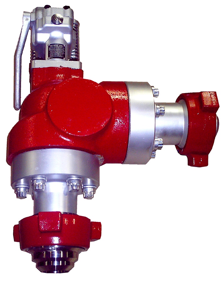
Pressure relief valves are installed on mud pumps in order to prevent an overpressure which could result in a serious damage of the pump and serious or fatal injury to personnel.
The discharge pressure is routed to the closer mud tank, via a 3” XXS line clamped strongly on tank side . Mud is flowing into the mud tank until line bled off, bearing in mind that minimum slope is required to avoid mud settling in pipe ( around 1 inch/meter).
In any cases if you don’t know/ clearly understand how to do it don’t do it, ask your supervisor. Do not start or later on , stop the job if you feel to do so .
Pressure relief valves are set usually to 90% of the maximum working pressure of the liners in use. Read carefully manufacturer chart for pressure setting versus size of liners.
With a low pressure setting, ie, 1000psi, by adjusting the top nylon self lock nut to move on the vertical scale to get the same setting than the scale.
Discharge pressure losses close to the maximum preset pressure.The Pressure relief valves are usually installed on a upper point of the discharge side of the mud pumps.
The pressure relief valve can be reset, if not damaged during the release of pressure. Special care should be taken if no working platform available to access the PRV.

If you run a mud rig, you have probably figured out that the mud pump is the heart of the rig. Without it, drilling stops. Keeping your pump in good shape is key to productivity. There are some tricks I have learned over the years to keeping a pump running well.
First, you need a baseline to know how well your pump is doing. When it’s freshly rebuilt, it will be at the top efficiency. An easy way to establish this efficiency is to pump through an orifice at a known rate with a known fluid. When I rig up, I hook my water truck to my pump and pump through my mixing hopper at idle. My hopper has a ½-inch nozzle in it, so at idle I see about 80 psi on the pump when it’s fresh. Since I’m pumping clear water at a known rate, I do this on every job.
As time goes on and I drill more hole, and the pump wears, I start seeing a decrease in my initial pressure — 75, then 70, then 65, etc. This tells me I better order parts. Funny thing is, I don’t usually notice it when drilling. After all, I am running it a lot faster, and it’s hard to tell the difference in a few gallons a minute until it really goes south. This method has saved me quite a bit on parts over the years. When the swabs wear they start to leak. This bypass pushes mud around the swab, against the liners, greatly accelerating wear. By changing the swab at the first sign of bypass, I am able to get at least three sets of swabs before I have to change liners. This saves money.
Before I figured this out, I would sometimes have to run swabs to complete failure. (I was just a hand then, so it wasn’t my rig.) When I tore the pump down to put in swabs, lo-and-behold, the liners were cut so badly that they had to be changed too. That is false economy. Clean mud helps too. A desander will pay for itself in pump parts quicker than you think, and make a better hole to boot. Pump rods and packing last longer if they are washed and lubricated. In the oilfield, we use a petroleum-based lube, but that it not a good idea in the water well business. I generally use water and dish soap. Sometimes it tends to foam too much, so I add a few tablets of an over the counter, anti-gas product, like Di-Gel or Gas-Ex, to cut the foaming.
Maintenance on the gear end of your pump is important, too. Maintenance is WAY cheaper than repair. The first, and most important, thing is clean oil. On a duplex pump, there is a packing gland called an oil-stop on the gear end of the rod. This is often overlooked because the pump pumps just as well with a bad oil-stop. But as soon as the fluid end packing starts leaking, it pumps mud and abrasive sand into the gear end. This is a recipe for disaster. Eventually, all gear ends start knocking. The driller should notice this, and start planning. A lot of times, a driller will change the oil and go to a higher viscosity oil, thinking this will help cushion the knock. Wrong. Most smaller duplex pumps are splash lubricated. Thicker oil does not splash as well, and actually starves the bearings of lubrication and accelerates wear. I use 85W90 in my pumps. A thicker 90W140 weight wears them out a lot quicker. You can improve the “climbing” ability of the oil with an additive, like Lucas, if you want. That seems to help.
Outside the pump, but still an important part of the system, is the pop-off, or pressure relief valve. When you plug the bit, or your brother-in-law closes the discharge valve on a running pump, something has to give. Without a good, tested pop-off, the part that fails will be hard to fix, expensive and probably hurt somebody. Pop-off valve are easily overlooked. If you pump cement through your rig pump, it should be a standard part of the cleanup procedure. Remove the shear pin and wash through the valve. In the old days, these valves were made to use a common nail as the shear pin, but now nails come in so many grades that they are no longer a reliable tool. Rated shear pins are available for this. In no case should you ever run an Allen wrench! They are hardened steel and will hurt somebody or destroy your pump.
One last thing that helps pump maintenance is a good pulsation dampener. It should be close to the pump discharge, properly sized and drained after every job. Bet you never thought of that one. If your pump discharge goes straight to the standpipe, when you finish the job your standpipe is still full of fluid. Eventually the pulsation dampener will water-log and become useless. This is hard on the gear end of the pump. Open a valve that drains it at the end of every job. It’ll make your pump run smoother and longer.

This website is using a security service to protect itself from online attacks. The action you just performed triggered the security solution. There are several actions that could trigger this block including submitting a certain word or phrase, a SQL command or malformed data.

Mud pump is one of the most critical equipment on the rig; therefore personnel on the rig must have good understanding about it. We’ve tried to find the good training about it but it is very difficult to find until we’ve seen this VDO training and it is a fantastic VDO training about the basic of mud pumps used in the oilfield. Total length of this VDO is about thirteen minutes and it is worth to watch it. You will learn about it so quickly. Additionally, we also add the full detailed transcripts which will acceleate the learning curve of learners.
Powerful mud pumps pick up mud from the suction tank and circulate the mud down hole, out the bit and back to the surface. Although rigs usually have two mud pumps and sometimes three or four, normally they use only one at a time. The others are mainly used as backup just in case one fails. Sometimes however the rig crew may compound the pumps, that is, they may use three or four pumps at the same time to move large volumes of mud when required.
Rigs use one of two types of mud pumps, Triplex pumps or Duplex pumps. Triplex pumps have three pistons that move back-and-forth in liners. Duplex pumps have two pistons move back and forth in liners.
Triplex pumps have many advantages they weight 30% less than a duplex of equal horsepower or kilowatts. The lighter weight parts are easier to handle and therefore easier to maintain. The other advantages include;
• One of the more important advantages of triplex over duplex pumps, is that they can move large volumes of mud at the higher pressure is required for modern deep hole drilling.
Triplex pumps are gradually phasing out duplex units. In a triplex pump, the pistons discharge mud only when they move forward in the liner. Then, when they moved back they draw in mud on the same side of the piston. Because of this, they are also called “single acting.” Single acting triplex pumps, pump mud at a relatively high speeds. Input horsepower ranges from 220 to 2200 or 164 to 1641 kW. Large pumps can pump over 1100 gallons per minute, over 4000 L per minute. Some big pumps have a maximum rated pressure of over 7000 psi over 50,000 kPa with 5 inch/127 mm liners.
Here is a schematic of a triplex pump. It has three pistons each moving in its own liner. It also has three intake valves and three discharge valves. It also has a pulsation dampener in the discharge line.
Look at the piston at left, it has just completed pushing mud out of the liner through the open discharge valve. The piston is at its maximum point of forward travel. The other two pistons are at other positions in their travel and are also pumping mud. But for now, concentrate on the left one to understand how the pump works. The left piston has completed its backstroke drawing in mud through the open intake valve. As the piston moved back it instead of the intake valve off its seat and drew mud in. A strong spring holds the discharge above closed. The left piston has moved forward pushing mud through the now open discharge valve. A strong spring holds the intake valve closed. They left piston has completed its forward stroke they form the length of the liner completely discharging the mud from it. All three pistons work together to keep a continuous flow of mud coming into and out of the pump.
Crewmembers can change the liners and pistons. Not only can they replace worn out ones, they can also install different sizes. Generally they use large liners and pistons when the pump needs to move large volumes of mud at relatively low pressure. They use a small liners and pistons when the pump needs to move smaller volumes of mud at a relatively high pressure.
In a duplex pump, pistons discharge mud on one side of the piston and at the same time, take in mud on the other side. Notice the top piston and the liner. As the piston moves forward, it discharges mud on one side as it draws in mud on the other then as it moves back, it discharges mud on the other side and draws in mud on the side it at had earlier discharge it. Duplex pumps are therefore double acting.
Double acting pumps move more mud on a single stroke than a triplex. However, because of they are double acting they have a seal around the piston rod. This seal keeps them from moving as fast as a triplex. Input horsepower ranges from 190 to 1790 hp or from 142 to 1335 kW. The largest pumps maximum rated working pressure is about 5000 psi, almost 35,000 kPa with 6 inch/152 mm linings.
A mud pump has a fluid end, our end and intake and the discharge valves. The fluid end of the pump contains the pistons with liners which take in or discharge the fluid or mud. The pump pistons draw in mud through the intake valves and push mud out through the discharge valves.
The power end houses the large crankshaft and gear assembly that moves the piston assemblies on the fluid end. Pumps are powered by a pump motor. Large modern diesel/electric rigs use powerful electric motors to drive the pump. Mechanical rigs use chain drives or power bands (belts) from the rig’s engines and compounds to drive the pump.
A pulsation dampener connected to the pump’s discharge line smooths out surges created by the pistons as they discharge mud. This is a standard bladder type dampener. The bladder and the dampener body, separates pressurized nitrogen gas above from mud below. The bladder is made from synthetic rubber and is flexible. When mud discharge pressure presses against the bottom of the bladder, nitrogen pressure above the bladder resists it. This resistance smoothes out the surges of mud leaving the pump.
Here is the latest type of pulsation dampener, it does not have a bladder. It is a sphere about 4 feet or 1.2 m in diameter. It is built into the mud pump’s discharge line. The large chamber is form of mud. It has no moving parts so it does not need maintenance. The mud in the large volume sphere, absorbs this surges of mud leaving the pump.
A suction dampener smooths out the flow of mud entering into the pump. Crewmembers mount it on the triplex mud pump’s suction line. Inside the steel chamber is a air charged rubber bladder or diaphragm. The crew charges of the bladder about 10 to 15 psi/50 to 100 kPa. The suction dampener absorbs surges in the mud pump’s suction line caused by the fast-moving pump pistons. The pistons, constantly starts and stops the mud’s flow through the pump. At the other end of the charging line a suction pumps sends a smooth flow of mud to the pump’s intake. When the smooth flow meets the surging flow, the impact is absorbed by the dampener.
Workers always install a discharge pressure relief valve. They install it on the pump’s discharge side in or near the discharge line. If for some reason too much pressure builds up in the discharge line, perhaps the drill bit or annulus gets plugged, the relief valve opens. That opened above protects the mud pump and system damage from over pressure.
Some rig owners install a suction line relief valve. They install it on top of the suction line near the suction dampener. They mount it on top so that it won’t clog up with mud when the system is shut down. A suction relief valve protects the charging pump and the suction line dampener. A suction relief valve usually has a 2 inch or 50 mm seat opening. The installer normally adjusts it to 70 psi or 500 kPa relieving pressure. If both the suction and the discharged valves failed on the same side of the pump, high back flow or a pressure surge would occur. The high backflow could damage the charging pump or the suction line dampener. The discharge line is a high-pressure line through which the pump moves mud. From the discharge line, the mud goes through the stand pipe and rotary hose to the drill string equipment.

Positive displacements pumps are generally used on drilling rigs to pump high pressure and high volume of drilling fluids throughout a drilling system. There are several reasons why the positive displacement mud pumps are used on the rigs.
The duplex pumps (Figure 1) have two cylinders with double acting. It means that pistons move back and take in drilling mud through open intake valve and other sides of the same pistons, the pistons push mud out through the discharge valves.
When the piston rod is moved forward, one of intake valves is lift to allow fluid to come in and one of the discharge valve is pushed up therefore the drilling mud is pumped out of the pump (Figure 2).
On the other hand, when the piston rod is moved backward drilling fluid is still pumped. The other intake and discharge valve will be opened (Figure 3).
The triplex pumps have three cylinders with single acting. The pistons are moved back and pull in drilling mud through open intake valves. When the pistons are moved forward and the drilling fluid is pushed out through open discharge valves.
When the piston rods are moved forward, the intake valves are in close position and the discharge valves are in open position allowing fluid to discharge (Figure 5).
On the contrary when the piston rods are moved backward, the intake valve are opened allowing drilling fluid coming into the pump (Figure 6). This video below shows how a triplex mud pump works.
Because each pump has power rating limit as 1600 hp, this will limit capability of pump. It means that you cannot pump at high rate and high pressure over what the pump can do. Use of a small liner will increase discharge pressure however the flow rate is reduces. Conversely, if a bigger liner is used to deliver more flow rate, maximum pump pressure will decrease.
As you can see, you can have 7500 psi with 4.5” liner but the maximum flow rate is only 297 GPM. If the biggest size of liner (7.25”) is used, the pump pressure is only 3200 psi.
Finally, we hope that this article would give you more understanding about the general idea of drilling mud pumps. Please feel free to add more comments.

Created specifically for drilling equipment inspectors and others in the oil and gas industry, the Oil Rig Mud Pump Inspection app allows you to easily document the status and safety of your oil rigs using just a mobile device. Quickly resolve any damage or needed maintenance with photos and GPS locations and sync to the cloud for easy access. The app is completely customizable to fit your inspection needs and works even without an internet signal.Try Template
Fulcrum helps us improve our processes and make our work environment safer by streamlining inspections, surfacing inspection-related insights, and managing follow-up actions. Once you close the loop from action to insight to further action, the possibilities are limitless.
Fulcrum lets employees on the floor who actually are building the product take ownership. Everyone’s got a smartphone. So now they see an issue and report it so it can be fixed, instead of just ignoring it because that’s the way it’s always been done.
One of the big things you can’t really measure is buy-in from employees in the field. People that didn’t want to go away from pen and paper and the old way of doing things now come to us and have ideas for apps.
Easy to custom make data collection forms specific to my needs. Very flexible and I can add or adjust data collection information when I need it. The inclusion of metadata saves a lot of time.
It is so easy to use. You don"t have to be a GIS specialist or coder to set up the app. Just a regular person is able to set up their own app and use it.
Fulcrum is, without a doubt, the best thing I"ve done for my business in regards to cost saving and time efficiency. Support is very good and help, on the rare occasions it"s required, is never far away.

For 50 years, Giant Pumps has offered the most dependable positive displacement high-pressure triplex pumps available. Designed and built to the highest quality standards, customers count on Giant Pumps products to keep their equipment running. Every design detail of Giant Pumps products is optimized for long-life and reliable performance, making Giant Pumps the most trusted name in high-pressure pumps and systems.
5-1. Mud Rotary Drilling. Rotary drilling with mud is the most widely used method for water-well construction. A rotary drill rig has three functions: rotating the drill string, hoisting the drill string, and circulating the drilling fluid. A bit is rotated against the formation while mud is pumped down the drill pipe, through ports in the bit, and back to the ground surface through the annulus between the drill pipe and the borehole wall. (Table 5-1 shows the relative performance of drilling methods in various geologic formations.) Drill cuttings rise to the ground surface in the drilling fluid. Rotary drilling is sometimes called mud rotary drilling. Drill pipes or rods are joined to a bit to form the drill string. The drill pipe is the link transmitting torque from the rig to the bit, and the pipe carries the drilling fluid down the hole.
a. Rotary Rigs. Rotary rigs vary in design. Drilling rigs are truck- or trailer-mounted and are powered by an on-board engine or by a PTO from the truck transmission. Power is delivered to the various components through hydraulic pumps and motors or through mechanical transmissions and clutches and geared on roller-chain drives. Many drill rigs may use both mechanical and hydraulic drives. Torque is applied to the drill string, which rotates by using three basic designs--rotary table, top head, and quill-and-drive bar. Military drilling machines use rotary table drives.(1) Rotary Table. The rotary table is a rotating platform that transmits torque to the drill rod through the kelly. The kelly, which is attached to the mud swivel, is the uppermost section of the drill string that passes through the rotary table. The drill string may be square, hexagonal, or round with grooves or flukes on the outside wall. The drive kelly bar slides through the rotary table while rotating. By removing the kelly bar, you can add drill pipe and work the pipe through the open hole in the rotary table. The rotary table normally is a mechanical, positive drive mechanism.
(2) Top Head. The top-head drive uses a power swivel. Torque is applied at the top of the drill string. The top-head mechanism moves down along the rig mast as the boring is advanced and is raised to the top of the mast to add a length of drill pipe. Top-head-drive drill rigs do not use a kelly bar. Most top-head drives are powered by hydraulic motors capable of variable speeds rather than positive constant rotation.
(3) Feed Drive. Rotary rigs are equipped with a mechanism to apply a downward thrust to the drill string. This mechanism is called a pulldown or feed drive.
Generally, two roller chains apply the thrust for rotary tables. The chains are attached to the kelly swivel and extended over sprockets at the top of the mast and under the rotary table. On older rigs, the sprockets under the rotary table are powered mechanically through a PTO and clutch. The pulldown chains on modem drill rigs are powered by a hydraulic motor, which provides better thrust control.
The thrust mechanism on most top-head rigs is a pair of roller chains consisting of two chain sections. One end of each section is attached to the swivel at the top of the kelly bar. The other ends are dead-headed to the top and bottom of the mast. Sprockets at the top and bottom of the mast act as idlers. Chains are powered in either direction by hydraulic rams. These rams apply thrust and are used in a hold-back mode to reduce the bit load of the weight due to the drill string. This chain mechanism is also the main hoist for lifting the drill string.
(4) Mud Pump. A mud pump (Figure 5-1) on a rotary drill is usually a positive-displacement, double-acting piston pump with capacities ranging from one to several hundred GPM at pressures up to several hundred psi. Power may be provided through a mechanical PTO and clutch, with or without a separate transmission. Power may also be provided by a separate engine or a hydraulic or air motor. Other types of pumps are often used successfully, but their limited pressure capacity may jeopardize the success of the drilling operation. Most well-drilling machines have dual piston, double-acting, positive-displacement mud pumps. Pump capacity (volume and pressure) can limit the effective depth of a drilling operation. The horsepower required to drive a mud pump often exceeds the power required to hoist and rotate the drill string.
b. Drill Bits. See Table 5-2 for recommended rotating speeds for all sizes and types of bits in various formations. See Figure 5-2 for bit selection. Appendix E discusses characteristics and maintenance for drill bits.
(2) Drag Bits. These bits are used in soil and other unconsolidated materials. The blades are designed so that they cut into the formation with a carving or scraping action. Drag bits may have multiblade, hardened-steel, finger-shaped teeth or may have connected carbide-reinforced cutting edges.
c. Rotary Operation. Standard rotary drilling involves the bit rotating against the formation. Drilling fluid is pumped through the drill string and face of the drill bit and backup the annulus to the surface. The rotary action of the bit loosens the material, while the drilling fluid cools and lubricates the drill pipe and bit and carries cuttings to the surface. The drilling fluid is under high hydrostatic pressure and supports the wall of the borehole against caving. The properties of the drilling fluid are important to the drilling operation. Well drillers must have knowledge of drilling fluids and their use for successful rotary drilling. Drillers must also know about drilling-fluid additives used to prevent problems in drilling. Preventing drilling problems, such as an unstable borehole wall or a stuck tool, is easier than fixing the problem after it occurs. See paragraph 5-1e for information on drilling fluids.
Before drilling with mud, build a mud pit. The pit may be either a portable pit or an excavated mud pit. The decision depends on the hole depth and the alternatives available. See paragraph 5-1e(9) for more information on mud pits.
d. Variables. Bit design, weight on bit, rotation speed, fluid consistency, and cumulation pressure and velocity affect rotary drilling. Experience helps the driller handle unique problems and conditions. Continue to experiment wherever you drill to develop the best drilling procedure. Before starting the hole, plumb the kelly to provide a straight hole (Figure 5-3).
(2) Weight on Bit. Adding weight on the bit increases the torque required for rotation. Too much weight can cause excessive penetration and produce cuttings that are too large and heavy. Large cuttings are difficult to wash out and may cause gumming and premature failure of the bit. Insufficient weight reduces or stops penetration and can produce fine cuttings. In cohesive soils, fine cuttings may thicken the drilling fluid and fail to settle in the mud pit. How weight is applied can also cause serious alignment problems and difficulty in well construction. Rotary-drilled boreholes spiral slightly and are seldom straight. Once spindling occurs, weight added by pulling down with the drill rig bends the string and magnifies the deviation. You should never use the chain pulldown to advance the hole beyond the first run (20 feet). Ideally, keep the drill string in tension. Add drill collars (heavy wall drill steel) at the bottom just above the bit. See Table 5-3 for drill collar weights.
Bit weight required to cut rock depends on the design of the bit and the strength of the rock. Roller bits need a minimum of 2,000 psi of bit diameter for soft rock and shale and a maximum of 6,000 psi of bit diameter for hard rock. Before drilling, add drill collars instead of drill pipe until the load is sufficient for reasonable cutting. As you dig deeper and add drill pipe, you may have to hold back on the drill string. See Table 5-4 for weight on bit and rotary speed.
(4) Rotation Speed. Rotation speed is determined by the weight on the bit and the material being drilled. Try to regulate the speed to produce the correct size cuttings. Experience will help you determine and regulate rotation speed.
(5) Fluid Requirements. Fluid requirements depend on size, weight, nature of cuttings, and circulation velocity. Velocity depends on capacity and condition of the mud pump, annular area in the borehole, and the stability and permeability of the formation. See paragraph 5-1e for more information on drilling fluids.
(6) Circulation Pressure and Velocity. These elements of the drilling fluid are controlled by the pump capacity and speed. The fluid"s density, velocity, and viscosity let it carry cuttings. If the drilling fluid is too thick, cuttings will not settle in the mud pit. Sufficient velocity with a fluid of low viscosity (even water) will carry drill cuttings to the surface. Excessive velocity will erode the wall of the hole to the extent of failure.
Pump pressure results from flow resistance caused by viscosity, friction, weight of the fluid column, or restrictions in the circulating system. Pressure should be exerted at the ports in the bit, causing a downward jetting as the fluid exits. Regulate mud-pump pressure by varying the RPM of the pump. Mud-pump pressure against the bit is not harmful if it does not exceed the operating pressure of the pump. Other sources of fluid pressure can be detrimental. Pressure from friction occurs if the drill string is long for its inside diameter or pipes are internally upset. Frictional pressure increases wear in the pump. Pressure from the weight of the fluid column in the annulus or from a restriction in the annulus caused by an accumulation of cuttings indicates insufficient cleaning. This type of pressure can cause formation damage, resulting in lost circulation and wall damage.
(7) Stabilizers. Unless the drill string includes stabilizers (Figure 5-5) for large drill bits, drill a pilot hole, using drill collars as stabilizers. The initial pilot hole (6- to 7 1/8-inch diameter) will be straighter and easier to sample. The location of aquifers will also be easier to determine. Use a larger bit to ream the hole to the desired size. Use overreaming bits, if available, because they follow the pilot hole best.
e. Drilling Fluids. Drilling fluid is circulated in rotary drilling to cool, clean, and lubricate the drill string, to flush cuttings from the hole, and to stabilize the borehole wall. Water is the basic fluid and is satisfactory for lubricating and cooling the tools. However, water has limited abilities to carry cuttings and stabilize the borehole wall. Many drilling fluid additives are prepared and formulated for various purposes. Polymer fluids and water-based clay fluids (muds) are the primary additives used in water-well drilling. Table 5-5 lists drilling fluids.
Mud cools and lubricates through heat absorption from the bit and reduction of drill-string abrasion against the borehole wall. Heat is generated as the bit scrapes and grinds. Without the cooling fluid, the bit would overheat and be useless. Research indicates that removing the cuttings around and under the bit is the most important factor in keeping the bit cool. Requirements for cooling fluid are less than those for removing the cuttings.
Therefore, if you keep the borehole clean with the fluid as you drill, you also cool and lubricate. This is true with clay muds and polymer fluids. Clay muds are colloidal suspensions. Solutions are chemical mixtures that cannot be separated by simple filtering. Suspensions are physical mixtures of solids and liquid that can be separated by filtering. This distinction underlies the difference in behavior between drilling polymers (solutions) and drilling muds (suspensions). You can mix natural clays with water for use as a drilling mud. Drillers often use water in shallow clayey strata and depend on the formation clay to produce a suitable mud. Natural-clay mud properties are marginal for good water-well drilling.
Hydrostatic pressure allows the fluid to support the borehole wall and is a function of the density or weight of the mud column. Important characteristics of a drilling mud are viscosity and weight to carry cuttings, gel strength, yield point, and active clay solids for filter cake. Use the following formula to calculate hydrostatic pressure:
(1) Polymers. Polymer fluids are water-based and very low in solids. The polymer admixture can be organic, inorganic, natural, synthetic or synthetically formulated natural polymers. Polymer additives are formulated for various drilling-fluid purposes and can be used alone or to enhance clay muds. Polymers, containing salt and other contaminants, are available and are compatible with water. Polymers are more sensitive to pH than are bentonite muds. Change the pH to effect desirable changes in the polymer fluid. Drilling-fluid weight impacts drilling rate and high-density drilling fluid reduces drilling rote. There is strong indication that the solids of a fluid have a similar effect as density. Polymer fluids are very different from clay muds because a large part of the polymer is soluble in water and becomes a solution when mixed with water. Long, complicated molecular chains tie up the water and can build viscosity without solids. In water-well drilling, many polymers are manufactured for producing drilling fluids, such as E-Z Mud, Revert, and Poly-Sal. E-Z Mud is a synthetic, inorganic polymer. Revert is a natural, organic polymer fluid derived from the guar plant.
Polymers are generally best mixed through a mud gun. Polymers used for special purposes are available from the manufacture complete with specifics on how to use the product. Most polymers can hydrate more water than a high-grade bentonite. Up to ten times more bentonite is needed to build the same viscosity in a given amount of fluid, depending on the quality of the polymer. A polymer does not fully hydrate as quickly as bentonite. Mix the polymer very slowly through the mud gun a minimum of four hours before using for more complete hydration. The fluid will thicken as hydration continues, so do not mix to the desired viscosity. Some polymers possess physical qualities that can result in unusual hydration, gelling and viscosity. Follow the manufacturer"s recommendations for hydration. Factors that affect the viscosity are quality of polymer, concentration and size of colloid, metallic ions in mixing water, temperature, rate of shear, and pH.
Water is the primary building block for drilling fluids. Water quality affects the overall performance of drilling fluids. The action of bentonite in water is seriously impaired by dissolved acids or salty substances. Acidic water usually contains dissolved metals that cannot be used unless treated. Hard water affects the suspending and sealing qualities of bentonite. You can test the pH level by using paper pH strips. The pH level should be 8 to 9. If the water is too acidic, treat it with soda ash at a ratio of 1 to 5 pounds of soda ash per 100 gallons of water. Following treatment, retest the pH level as before.
Do not use water from wetlands, swamps, or small ponds for mixing drilling fluids because the water may be contaminated. If you use water from these sources, chlorinate the water before making the drilling fluid. Be careful because chlorine removes metallic ions that are necessary for viscosity in polymers. Adjust the pH of drilling water to 7.5.
Temperature affects the viscosity and stability of some polymers. Consider the following examples:Seven pounds of Revert per 100 gallons of water at 45°F yields Marsh funnel viscosity of 125 seconds per quart. The same mix at 85°F yields 70 seconds per quart.
A 0.87 weight mix of Revert at 68°F F yields a viscosity above 90 seconds per quart for three and a half days. The same mix at 80°F maintains viscosity of 80 seconds per quart for only two days.
Polymer drilling fluids can break down viscosity. Without treatment, the viscosity of some polymers (Revert) completely breaks down in one to six days depending mainly on temperature. You can correct this by adding chlorine. Revert requires Fast Break; E-Z Mud needs sodium hypochlorite at a ratio of 2 quarts for every 100 gallons of water. Other polymers, such as E-Z Mud and Poly-Sal, maintain their viscosity for long periods of time since natural breakdown is not significant. Table 5-6 lists additives for drilling fluids.
Some drilled fines (clay, silt) circulate back down the hole. Recirculated solids are much less a problem with polymer fluids than with clay fluids. Revert will not hydrate in water containing any appreciable amount of borate. However, Borax can be used to produce a gel plug in hydrated guar-gum polymer. With a pH of 7.5, the borate cross-links the polymeric chains and forms a strong three-dimensional molecular gel. If a strong gel plug is necessary to get through a lost circulation zone, mix 1 cup of borax in 5 gallons of water and pour slowly into the pump section while pumping at idle speed. When the berated fluid (stringy gelled mass) recirculates, stop pumping for one-half hour. Resuming normal drilling should be possible after wasting the borated fluid. Repeat the procedure, if necessary. Although the polymer fluid is not thixotropic and has no gel strength, it thins somewhat while being pumped.
Polymer fluids build a type of membrane on the wall different from clay mud. Unnatural clay particles (bentonite) are not introduced into the hole. Since the polymer fluid is partly a thick solution, infiltration into the permeable wall is reduced. However, insoluble portions of some polymer colloids do exist. The insoluble and cuttings are surrounded with thick coatings that are more impermeable per unit thickness than a bentonite filter cake. The insoluble and cuttings seal the wall of the hole with a thinner, less active layer. The impermeable layer performs the same function as the filter cake in clay muds but does not restrict the annulus.
The colloids in the polymer fluid are nonionic, have no chemical interaction, and are easier to remove in water-well development. When the viscosity of the fluid is broken, much of the cohesive function of the thin film becomes a water-like liquid and is washed out of the water well. Field testing of polymer fluids, using the falter press and the Marsh funnel, yields different results. The mud balance for measuring fluid density does not change. Weighing of the polymer fluid is limited. You can add sodium chloride to the fluid to bring the weight up to about 10 pounds per gallon. The addition of heavy solids (ground barite) is ineffective because of the polymer fluid"s lack of thixotropic qualities.
(2) Mud Products. Commercially processed clays for drilling are bentonite and attapulgite. Bentonite is superior except in brackish or salty water. (Use attapulgite in these waters.) Bentonite forms naturally from decomposition of volcanic ash when ground. Bentonite consists of aggregates of flat platelets in face-to-face contact. Bentonite is mined in many states, but the best grade (Wyoming bentonite) is mined only in Wyoming and South Dakota. Wyoming bentonite contains sodium montmorillonite (the active part of the clay mineral) and is small in size, which is important in building viscosity.
Mud drilling fluids should be mixed with a mud gun. When agitated and sheared with water, the bentonite platelets absorb more than 25 times their own weight in water, separate, and swell. The amount of surface area wetted determines the ability of the particle to build viscosity. One ounce of Wyoming bentonite dispersed in water has more surface area than five football fields. Interparticle activity between platelets gives the mud its gel properties. The chemical composition of the mixing water affects the ability of bentonite to develop desirable qualities. These qualities can be manipulated by adding small amounts of various chemicals.
(3) Mud Viscosity. True viscosity is a term relating only to true (Newtonian) fluids, such as water, and is a proportional constant between shear stress and shear rate in laminar flow. Drilling muds act differently in that the proportion between shear stress and shear rate is reduced when shear rate is increased. Drilling muds are thixotropic. The viscosity of a drilling mud refers to the thickness of the mud while flowing. Gel strength is the term used to describe the thickness of drilling mud at rest. Gel strength develops over a short period of time.
Yield point is the mud quality broadly included in viscosity. You need more stress (pump pressure) to cause the gelled drilling mud to start flowing than to sustain flow once the gel is broken. The stress required to initiate shear or flow is the gel strength of the mud. The stress required to maintain shear is the viscosity. You want a higher yield strength with respect to the gel strength so the mud becomes very thin in flow shear.
The primary function of viscosity is to help lift drill cuttings from the borehole. Other mud characteristics affecting lifting capacity are density, velocity, and flow patterns. Gel strength holds the cuttings in suspension at the bottom of the hole when circulation is stopped. The stress (hydraulic pressure) required to break the gel strength to initiate cumulation can be detrimental. Required bottom-hole pressures can cause fracturing or opening of fractures in the formation, resulting in loss of drilling fluid, formation damage, and borehole wall damage. Down-hole pressure required to continue circulation depends on friction, density (or weight of fluid column), and viscosity of the mobilized fluid. These pressures can also cause serious problems. Therefore, it is desirable to use a drilling mud of relatively low density and viscosity, moderate gel strength, and high yield point relative to the gel strength (a very thin fluid in circulation).
(4) Mud Testing. The Marsh funnel (Figure 5-6) is routinely used to give an indication of thickness or apparent viscosity of drilling fluid. The Marsh funnel is 12 inches long and 6 inches in diameter and has a No. 12 mesh strainer and a 1,000-milliliter (ml) cone. The funnel has a 2-inch-long, calibrated, hard-rubber orifice with an inside diameter of 3/16 inch. The funnel"s cup is marked with a capacity of 1,000 ml. Use the following procedure for the Baroid Marsh funnel:Hold or mount the funnel in an upright position, and place a finger over the hole.
The funnel viscosity measurement obtained is influenced considerably by the gelation rate of the mud sample and its density. Because of these variations, the viscosity values obtained with the Marsh funnel cannot be correlated directly with other types of viscometers and/or rheometers. Graduated in cubic centimeters (cc) and fluid ounces, the 1,000-cc measuring cup is designed specifically for use with the Baroid Marsh funnel viscometer. A quart volume is clearly marked on the measuring cup.
You can use test readings as an indicator of changes in mud that might lead to problems. Therefore, conduct Marsh-funnel tests before beginning operations and record the findings. Take mud samples for each test from the same location in the circulating system just before returning to the hole. The apparent viscosity of the drilling mud in motion affects carrying capacity, the pump pressure (hydrostatic down-hole pressure) required for circulation, and the ability to drop cuttings in the settling pit. These characteristics are also intrinsically involved with well hydraulics, density of mud, density and size of cuttings, and particle slip.
(5) Density. The carrying capacity of a mud is affected by its density and the density of the drill cuttings. If the cuttings are denser than the fluid, they will descend. The magnitude of the difference in density, particle size, and fluid viscosity affect the rate at which a particle descends. Particle slip denotes this downward movement through the fluid. Ignoring thixotropy, the actual downward particle slip is constant regardless of velocity of flow. However, when the upward velocity of fluid exceeds the downward particle slip, the new movement of the particle is upward. Up-hole velocity plays a major role in determining the carrying capacity of the cumulating fluid. The practical limits of up-hole velocity depend on pump size and capacity, inside diameter (ID) of the drill string, jet size in the bit, viscosity of the fluid, cross-sectional area of the annulus, and stability of the borehole wall. Up-hole velocity is not as simple as the comparison of pump capacity, drill string ID, and annulus. Up-hole velocity is not a constant.
The density of the drill fluid serves other purposes in rotary drilling. Heavy fluids can control (hold down) formation pressures encountered in drilling. You can build heavy mud by adding a weighing material such as ground barite (specific gravity 4.25). Prepare drilling mud in excess of 20 pounds per gallon by using barite. First, mix bentonite and water to build viscosity. Then, add finely ground barite so the mud will hold the barite in suspension. Use heavy drilling mud only when absolutely necessary to control pressures since the muds have disadvantages. High-density mud increases pressure on the formation by the weight of the fluid column. Figure 5-7 shows the nomograph for determining the hydrostatic head produced by drilling fluids. The increased pressure is further increased by the pump pressure required to mobilize the fluid in circulation. The increased pressure can cause formation damage and loss of circulation. In formations that are strong enough to withstand the pressures without being damaged, the drilling operation can still suffer.
All cuttings should be removed from the drilling mud in the settling pits and not recirculated. Although 100 percent removal is unrealistic, well-designed mud pits and mechanical screens, desanders, and desilters materially aid in removing cuttings from the mud. Water weighs 8.34 pounds per gallon. Clean, low-solid bentonite mud can weigh 8.5 to 9.0 pounds per gallon; try to maintain that weight. Increasing density of the mud during drilling indicates that the mud contains native solids. The drill"s penetration rate could be exceeding the combined effort of the mud pit, desanders, and fluids to effectively separate solids from the drilling mud. To correct this problem, slow down the penetration rate and run the desanders to remove the solids.
You can determine the density or weight of the drilling mud using a mud balance. Fill the mudbalance cup with mud, and place the inset lid in the cup. Excess mud will be displaced through a hole in the lid. Clean the outside cup area, place the assembly on the center pivot, and balance it using sliding weight. You read mud density as pounds per gallon and pounds per cubic feet. If you know the mud weight that enters and exits the drill hole, you can evaluate the efficiency of the mud pit and mechanical separators, determine when to clean the mud pit, and tell how well the mud is cleaning the hole. If you take samples from only one location, take them from the return end of the pit.
(6) Filter Cake. Filter cake consists of solids from the drilling mud deposited on the borehole wall as the water phase is lost into the formation. Desirable properties are thinness and impermeability. Drilling mud is a colloidal suspension that can be separated by simple filtering. With the hole kept full of mud, the hydrostatic pressure inside usually exceeds the formation pressure. Occasionally, an artisan aquifer is penetrated, with formation pressure higher than the hydrostatic in-hole pressure. When the borehole pressure is higher than the formation pressure, the drilling mud tends to penetrate more permeable formations. Solids from the mud filter out and deposit on the wall, and the liquid phase of the mud (filtrate) enters the formation.
Filter cake can be compacted against the wall by the excess hydrostatic pressure in the borehole. If the drilling mud is a well-conditioned bentonite and water mixture, most of the solids plastered against the wall will be flat platelets of highly active clay. The filter cake is self-regulating based on its degree of impermeability. As long as filtrate can pass through, the filter cake continues to thicken. A thick cake detrimentally increases down-hole cumulating pressure by restricting the annulus, making it difficult to pull the drill string because of the physical size of the drill collars and bit. In deep and somewhat deviated holes, the danger of key seating increases. Because a thick filter cake is of a lower quality and depends on its thickness to be effective, it is more easily damaged and eroded. A thick filter cake may indicate that the fluid has a high percentage of native solids. You may have to clean these solids from the mud before drilling progresses.
A thin, highly impermeable filter cake bonds well to the wall and provides a surface for the hydrostatic pressures to act against to support the wall. Filtrate loss into the formation can account for significant fluid loss, if the consistency of the drilling mud is not good. Good consistency does not necessarily mean thick; it has to do with the bentonite content and the quality of falter cake. If a permeable formation is encountered with pore spaces too large to be plugged by the fine bentonite particles, the drilling mud will enter the formation. That mud loss can take the entire output of the mud pump. The drill cuttings being carried up the annulus can sometimes be beneficial. The cuttings are coarser than the bentonite particles and may help bridge across formation pores. If you use this technique, maintain the normal drilling rate to supply the cuttings. Slow down the pumping rate to reduce pressure on the formation while bridging the open spaces. With sufficient bridging, a suitable filter cake follows, circulation is regained, and normal drilling operations are resumed.
In the field, you can test the filtration properties and filter-cake thickness using the filter-press kit. This kit consists of a press with a mounted pressure gauge and a CO2 charging system that is used to simulate the hydrostatic pressure inside a 200-foot hole. By placing a sample of drilling mud in the press and charging the system, you can forma filter cake. The filter cake should be less than 2/32-inch thick.
(7) Salty Environment. A high chloride content in the mixing water causes bentonite to react anomalously or not react at all. The ground bentonite remains agitated; it does not disperse, hydrate, or swell. In salt water, bentonite is an inefficient clay additive for drilling mud. The dissolved salt is an electrolyte that changes the interparticle activity of bentonite. If you add sufficient amounts of salt water to a fresh water and bentonite mud mixture, the dispersed platelets will form lumps. Viscosity and filtrate loss increase and the mud"s ability to build a thin, impermeable filter cake decreases.
Attapulgite is often used for salty formations. The small particles produce a high surface-area-to-volume relationship and good viscosity building. Unlike bentonite, the particle shape is needle-like. Viscosity building in attapulgite depends on the entanglement of these needles. The disorderly arrangement of the particles accounts for the poor filtration qualities of attapulgite. The filter cake is more like a layer of strew or sticks. Attapulgite clay does not have the physical qualities to build a thin, impermeable filter cake. If you can mix bentonite in fresh water first and then add salt water as make-up water, the bentonite flocculates; that flocculation can be reversed by chemical treatment.
(8) Well Hydraulics. You must have a basic understanding of well hydraulics. Fluid is pumped down the drill string, out the ports in the bit, and up the annular space between the drill string and the wall. The fluid empties into the mud pit, through any mechanical solids separating equipment, and is picked up from the pit by the mud pump for recirculation. The system is intended as a conservation system. Except for mud lost into the formation or where artisan water exceeding hydrostatic pressure flows into the hole, the return is largely complete and the mud-pit level does not change. Even if the system is in equilibrium, you need to understand the up-hole rearrangement of flow patterns.
Fluids flow in two distinct patterns. Laminar flow is orderly. The streamlines remain distinct and the flow direction at every point remains unchanged with time. Turbulent flow is disorderly. The flow lines and directions are confined and heterogeneously mixed. The type of flow depends on the cross-sectional area of the fluid course and the velocity, density, and viscosity of the fluid. In water-well drilling, the cross-sectional area of the annulus is usually several times that of the inside diameter of the drill string. Because of the increase in volume in the annular space, flow at the point the fluid leaves the bit is turbulent. The fluid becomes laminar flow when it begins flowing up the annular space. The returning fluid velocity is slower and the drill fluid is more dense and probably has more apparent viscosity, which affects the flow pattern. To clean the hole and carry the drill cuttings out, turbulent flow in the annulus would be better.
Picture the flow in the annulus as a series of nested tubes. Velocity varies as if these tubes were sliding past one another while moving in the same direction. Flow near the wall and near the drill string is at a slower rate than near the center. Cuttings near the center can be vigorously lifted while cuttings near the wall and drill string actually slip in a net fall. Rotation of the drill string changes the flow pattern near the drill string and materially enhances particle lift.
For example, if you use a 3 1/2-inch ID and 4-inch outside diameter (OD) pipe to drill a 9-inch hole and pump 200 GPM, the velocity of the ID pipe is 400 feet per minute (fpm) and the velocity of the OD pipe is 75 fpm. To test cumulation at these rates (bit is 300 feet deep), pump down a marker (strew or oats). The majority of the material should take 4 minutes and 45 seconds to return (300 feet at 400 fpm takes 45 seconds and 300 feet at 75 fpm takes 4 minutes). To clean all the cuttings from a 300-foot depth with an average up-hole mud velocity of 75 fpm will require more than four minutes of pumping. Consider this concept regarding sampling cuttings from the return mud.
If cuttings remain in the annular space between the drill rod and borehole wall when circulation is stopped, they will produce a denser fluid than the clean drilling mud inside the drill rods. The denser mud in the annular space will then flow down the hole and force the clean drilling mud up the drill rods. This causes a geyser effect, and the drilling mud may shoot several feet into the air until the mud columns equalize. (Some drillers mistake this for a caving hole.) If this situation happens when adding drill rods, the circulation time should be increased after drilling down the next rod. Use the following formula to calculate the annular space volume:
(9) Mud Pits. Rotary chilling preparation is the design and excavation of an in-ground mud pit or installation of a portable mud pit and the mixing of the drilling fluid. For standard drilling operations that use well-completion kits, well depths could range from 600 to 1,500 feet. For wells up to 600 feet using the 600-foot WDS, use portable mud pits. For wells over 600 feet, use dug mud pits. In either case, you will have to clean cuttings from the pits as drilling progresses. Design considerations include the anticipated depth and diameter of the drill hole, since the material cuttings from the hole will be deposited in the mud pits.
The volume of the pits must equal the volume of the completed hole. Therefore, during drilling, you will have to clean the cuttings from the pits frequently. If you have a backhoe to dig and clean the pits, size and depth of the pits are not critical. If you must dig and clean the pits with shovels, width and depth are important. Drilled cuttings should drop out of suspension in the mud pit. Therefore, long, narrow pits are better. Figure 5-8 shows a mud-pit layout and a chart depicting mud pit capacities and dimensions.
Mud pits are part of the circulating system for mixing and storing drilling fluid and for settling cuttings. The ground slope will affect site layout. Pit design can enhance pit performance. Most drillers agree that using multiple pits is best when dropping drill cuttings from the fluid. The volume of the pit should be one and one-half to three times the volume of the hole. This will provide fluid to fill the hole and an excess volume to allow stilling and settlement or processing before returning to the drill string. A volume of three times the hole volume will minimize drilling-fluid and mud-pit maintenance. Figure 5-9 shows a mud pit that is prepared on-site. Figure 5-10 shows a portable mud pit.
If drilling mud is processed through shale shakers, desanders, desilters, and space and time for cuttings settlement are not important, long, narrow pits connected at opposite ends by narrow, shallow trenches are preferred. If using a polymer fluid that has no thixotropic qualities, the settlement of cuttings is a function of time at low velocity or no flow. With polymer fluid, a long-path mud pit is ideal; if part of the flow almost stops, cutting settlement is enhanced.
If you use a clay-based mud with thixotropic qualities and the mud moves slowly or flow stops, the gel strength can hold the cuttings. High velocity through narrow, shallow trenches holds the cuttings in suspension. If mud runs over one or more wide baffles or weirs, flow shear and velocity are low. These factors enhance cuttings to drop out. If mud processing equipment is available, use it. Recirculating clean fluid reduces power requirements, wear, and erosion and enhances drilling rate. See Figure 5-11 and Figure 5-12 to calculate weir dimensions and volume.
f. Rotary Drilling Problems. Some problems in rotary drilling are minor and others are serious and can result in failure to complete a hole or even loss of equipment. Many serious problems start minor but can become serious if not recognized or handled properly. For example, in a loose sand zone, the borehole walls can slough and cause drilling fluid loss. By reducing or increasing fluid velocity, you can stabilize the wall and regain fluid circulation. However, if you do not recognize the condition and you continue drilling, the wall will slough and create a cavity. The cuttings lose velocity, become suspended in the cavity, and tend to fall back into the hole when you add a rod. This action can result in the rods or the bit becoming stuck in the hole. Other problems can result from subtle changes in geology, imbalances in the drilling operation, or equipment failure.(1) Lost Circulation. Lost circulation refers to a loss in volume of drilling fluid returning to the surface. The implication is that some fluid pumped down the drill pipe is entering the formations. The mud pit will lower, since some of the mud is used in forming a mud cake on the borehole wall; however, increased lowering can indicate circulation loss. Losses can occur through open-graded sand or gravel or open joints in rock. A loss can occur when cuttings are not washed out and the borehole annulus becomes restricted, resulting in increased down- hole pressure. Spudding (raising and lowering the drill string) the hole too violently can cause loss. Spudding helps wash cuttings, but down-hole pressures increase momentarily. Experienced drillers can estimate when spudding is safe. When fluid cumulation is lost and a driller continues to drill, he is drilling blind. An experienced driller that knows the rig can often drill blind successfully, but reestablishing circulation is always safer.
Reestablishing circulation can involve several techniques. You can add commercial items such as chopped paper, straw, cottonseed, and nut hulls to the mud pit. Sometimes, while the loss zone is grouted and redrilled, the grout is lost into the formation. In this situation, you may have to set casing through the loss zone. Occasionally, reducing fluid velocity while continuing to drill will plug the loss zone with drill cuttings. Reestablishing circulation is usually a trial-and-error process. The longer you drill without circulation the more difficult it will be to reestablish circulation.
(2) Fall-In. Fall-in is material that accumulates in the bottom of the borehole after you stop cumulation. This material is borehole-wall material that results from sloughing or caving or cuttings previously carried in suspension. Fall-in occurs when you encounter a loose, unstable formation and the drilling-fluid weight is insufficient to stabilize the formation. If you anticipate or suspect fall-in, raise the drill bit off the bottom of the hole (20-foot minimum) each time drilling is interrupted. This will prevent the cuttings and fall-in from settling back around the bit until the problem is solved.
(3) Stuck Drill String. The drill bit and any collars just above the bit are larger in diameter than the drill pipe. The string becomes stuck when cuttings collect on the bit and collar shoulder. This condition is called sanded in. Be careful because you can break the drill pipe while trying to remove the drill string. Regaining circulation and working the sand out are seldom successful. If the formation will not take the fluid when you engage the pump clutch, the relief (pop-off) valve will operate to relieve the pressure. Little can be done to free the drill string except to wash a small pipe down the annulus to the bit and jet the settled sand back into suspension. When the annulus is too small to pass a jet pipe, a part of the drill string may be lost.
When the annulus is small, excessive up-hole velocity can promote erosion of the filter cake in granular zones and allow caving against the drill pipe. If this occurs, try to maintain circulation and rotation, even if circulation is slight. Where the grains are angular, the drill pipe can become locked while being rotated. This situation is similar to a sanded-in bit. With smooth pipe (not upset), hammering up and down will sometimes dislodge the string. You can reestablish circulation and continue drilling. Be careful because hammering up and down can produce unfavorable compacting of the sand. In a hole of fine-grained soil or shale, where the alignment has significantly deviated and the drill pipe has wallowed into the wall, the pipe can become wall stuck. Pipe friction and relatively high borehole pressure can move the pipe tighter into the wallowed groove as you pull the string. An alert driller should recognize early stages of deviation and take measures to realign the hole.
(4) String Failure. When the drill string parts, leaving a portion in the borehole, the drill string is rung off. The portion in the borehole is a fish and attempts to retrieve the portion is fishing. Fishing tools include a tapered tap and an overshot die (Figure 5-13). Ringing off is normally fatigue failure in the drill-rod joints caused by excessive torque or thrust (repeated flexing and vibration that crystallizes heat-treated tool joints) or by borehole deviation (with flexing of the string). Examine drill rods for signs of failure.
(6) Swelling Soil. The in-hole effects of swelling soil (shale or clay) that absorbs water from the drilling fluid is squeezing. The result is a borehole that is undergauged to the extent that you cannot pull the bit by normal hoisting methods. In such cases, you can cut back through the blockage with a roller rock-bit or a drag bit. Swelling can cause caving and failure of the wall. Keep water out of the formation to prevent swelling. Special polymer drilling fluid additives that limit water absorption are available. High quality bentonite forms a thin but highly impermeable filter cake.
5-2. Air Rotary Drilling. Air rotary drilling is similar to mud rotary drilling except that the fluid circulated is compressed air. The air is not recirculated. Using compressed air is advantageous when water for drilling is inconvenient, fluid is being lost to the formation while drilling, or you have difficulty washing sticky clay formations from the hole. Also, air rotary drilling requires much less development time. You may have to adjust air rotary techniques with each well you drill. Some disadvantages to air rotary drilling are that air cannot support the wall of a hole in an unstable formation, changes in the return air flow are not as readily apparent as in mud flow, and air is not as effective in cooling and lubricating the drill bit and string.
a. Air Supply. Air has no density or viscosity,


 8613371530291