
what pressure do you set pop off on mud pump brands
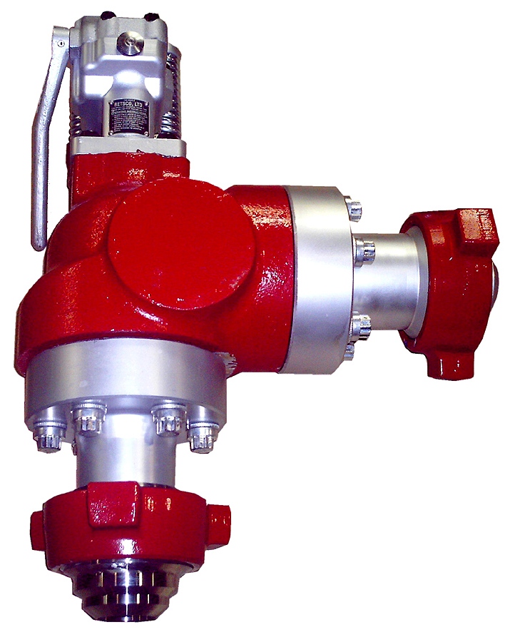
Pressure relief valves are installed on mud pumps in order to prevent an overpressure which could result in a serious damage of the pump and serious or fatal injury to personnel.
The discharge pressure is routed to the closer mud tank, via a 3” XXS line clamped strongly on tank side . Mud is flowing into the mud tank until line bled off, bearing in mind that minimum slope is required to avoid mud settling in pipe ( around 1 inch/meter).
In any cases if you don’t know/ clearly understand how to do it don’t do it, ask your supervisor. Do not start or later on , stop the job if you feel to do so .
Pressure relief valves are set usually to 90% of the maximum working pressure of the liners in use. Read carefully manufacturer chart for pressure setting versus size of liners.
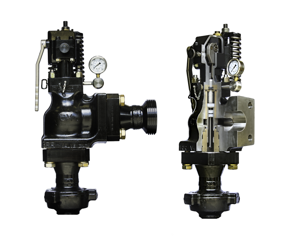
With a low pressure setting, ie, 1000psi, by adjusting the top nylon self lock nut to move on the vertical scale to get the same setting than the scale.
Discharge pressure losses close to the maximum preset pressure.The Pressure relief valves are usually installed on a upper point of the discharge side of the mud pumps.
The pressure relief valve can be reset, if not damaged during the release of pressure. Special care should be taken if no working platform available to access the PRV.

This website is using a security service to protect itself from online attacks. The action you just performed triggered the security solution. There are several actions that could trigger this block including submitting a certain word or phrase, a SQL command or malformed data.

1.1 OBJECTIVE.A key objective of ADC Procedures is to set up a step by step way of handling thejob. It is also an analysis of associated hazards pertaining to the jobs and measures tominimize the risks.This procedure has developed to be applied and discussed before each job listed inthe contents.1.2 SCOPE.This procedure applies to Rig AD-321.3 RESPONSIBILITY.It is the responsibility of the Tool-pusher and Rig Manager to insure all listedoperations are executed in a safe and efficient manner. It is their responsibility toconduct a Pre-job Safety Meeting and discuss and review the related JSA, prior tostarting each operation.Tool-pusher is responsible to ensure that each work permit has its dedicated JSAattached to.JSA to be reviewed and updated at least annually or When equipment is modified When processes are changed When material are changed When changing people/contractors When there is an accident or near miss.The Rig Sup. is accountable for keeping this document up-to date.The JSA date and the crew should be same as Work Permit date and crew.
Table of ContentsTASK ANALYSISIs Procedure relevant for the operation?What can interfere with the operation (Simops)?Who is going to be in charge, position?Who is giving instructions/signals, who replace him?How many people are required to do the job?-
Do you need a PTW/ Isolation (lockout, Tag out)?What is the PPE required?What tools/equipment do you need?Do you need a third party, crane, and forklift?Who else needs to know what you are doing?Do you need to barrier off the area?What are the safest access/escape routes?-
Pressure relief valves are installed on mud pumps in order to prevent an overpressurewhich could result in a serious damage of the pump and serious or fatal injury topersonnel.The discharge pressure is routed to the closer mud tank, via a 2 line minimum clamped allthe way along. Mud is flowing into the mud tank until 0 pressure in the line.Read carefully manufacturer instructions regarding setting, handling, refurbishing of suchequipment.In any cases if you dont know/ understand how to do it dont do it, ask your supervisor.1) Pressure relief valves are set usually to 90% of the maximum working pressure ofthe liners in use. Read carefully manufacturer chart for pressure setting versus sizeof liners.2) The most commonly used pressure relief valve is RETSCO, 500 and 750, whichstands for mud pumps maximum working pressure 5000psi and mud pumps7500psi.3) Prior to installing a pressure relief valve it needs to be tested on a bench.
nut to move on the vertical scale. If the pop off pressure matches the setting, then screw to the pressurerequired on the mud pump (check liner chart) and test again.
When the pressure test has been successful, put a tag on the pressure relief valve, whereit is mentioned:-The date of the test.-The pressure of the test.-If the pressure relief valve was reconditioned.Store it properly away from dust and adverse weather.
1) When/if the pressure relief valve activates due to: I_Bop kept closed and pump started. Build up pressure close to the maximum preset pressure.The pressure relief valve can be reset, if not damaged during the release of pressure.The Pressure relief valves are usually installed on a upper point of the discharge side ofthe mud pumps.Special care should be taken if no working platform available to access the PRV.A safety harness may be necessary in some places.1) Pull round button toward you.2) Pull handle towards you to reset / reposition the knuckle joint inside.3) The handle should have a hard point then come freely.4) If you cannot exert enough force due to position a 1 ID pipe can beused to pull the handle. DO NOT FORCE on the handle if nothingmoves, that means that the discharge piston inside is jammed.
7) Replace PRV by the one ready tested in the store.8) Restore the power on the mud pump.9) Start the pump slowly; check on the discharge pipe above the mudtanks if there are no leaks.10)If everything ok, close work permit, recondition worn pressure reliefvalve, with original parts, pressure test it and store it with a tag asmentioned earlier.
If you run a mud rig, you have probably figured out that the mud pump is the heart of the rig. Without it, drilling stops. Keeping your pump in good shape is key to productivity. There are some tricks I have learned over the years to keeping a pump running well.
First, you need a baseline to know how well your pump is doing. When it’s freshly rebuilt, it will be at the top efficiency. An easy way to establish this efficiency is to pump through an orifice at a known rate with a known fluid. When I rig up, I hook my water truck to my pump and pump through my mixing hopper at idle. My hopper has a ½-inch nozzle in it, so at idle I see about 80 psi on the pump when it’s fresh. Since I’m pumping clear water at a known rate, I do this on every job.
As time goes on and I drill more hole, and the pump wears, I start seeing a decrease in my initial pressure — 75, then 70, then 65, etc. This tells me I better order parts. Funny thing is, I don’t usually notice it when drilling. After all, I am running it a lot faster, and it’s hard to tell the difference in a few gallons a minute until it really goes south. This method has saved me quite a bit on parts over the years. When the swabs wear they start to leak. This bypass pushes mud around the swab, against the liners, greatly accelerating wear. By changing the swab at the first sign of bypass, I am able to get at least three sets of swabs before I have to change liners. This saves money.
Before I figured this out, I would sometimes have to run swabs to complete failure. (I was just a hand then, so it wasn’t my rig.) When I tore the pump down to put in swabs, lo-and-behold, the liners were cut so badly that they had to be changed too. That is false economy. Clean mud helps too. A desander will pay for itself in pump parts quicker than you think, and make a better hole to boot. Pump rods and packing last longer if they are washed and lubricated. In the oilfield, we use a petroleum-based lube, but that it not a good idea in the water well business. I generally use water and dish soap. Sometimes it tends to foam too much, so I add a few tablets of an over the counter, anti-gas product, like Di-Gel or Gas-Ex, to cut the foaming.
Maintenance on the gear end of your pump is important, too. Maintenance is WAY cheaper than repair. The first, and most important, thing is clean oil. On a duplex pump, there is a packing gland called an oil-stop on the gear end of the rod. This is often overlooked because the pump pumps just as well with a bad oil-stop. But as soon as the fluid end packing starts leaking, it pumps mud and abrasive sand into the gear end. This is a recipe for disaster. Eventually, all gear ends start knocking. The driller should notice this, and start planning. A lot of times, a driller will change the oil and go to a higher viscosity oil, thinking this will help cushion the knock. Wrong. Most smaller duplex pumps are splash lubricated. Thicker oil does not splash as well, and actually starves the bearings of lubrication and accelerates wear. I use 85W90 in my pumps. A thicker 90W140 weight wears them out a lot quicker. You can improve the “climbing” ability of the oil with an additive, like Lucas, if you want. That seems to help.
Outside the pump, but still an important part of the system, is the pop-off, or pressure relief valve. When you plug the bit, or your brother-in-law closes the discharge valve on a running pump, something has to give. Without a good, tested pop-off, the part that fails will be hard to fix, expensive and probably hurt somebody. Pop-off valve are easily overlooked. If you pump cement through your rig pump, it should be a standard part of the cleanup procedure. Remove the shear pin and wash through the valve. In the old days, these valves were made to use a common nail as the shear pin, but now nails come in so many grades that they are no longer a reliable tool. Rated shear pins are available for this. In no case should you ever run an Allen wrench! They are hardened steel and will hurt somebody or destroy your pump.
One last thing that helps pump maintenance is a good pulsation dampener. It should be close to the pump discharge, properly sized and drained after every job. Bet you never thought of that one. If your pump discharge goes straight to the standpipe, when you finish the job your standpipe is still full of fluid. Eventually the pulsation dampener will water-log and become useless. This is hard on the gear end of the pump. Open a valve that drains it at the end of every job. It’ll make your pump run smoother and longer.

This website is using a security service to protect itself from online attacks. The action you just performed triggered the security solution. There are several actions that could trigger this block including submitting a certain word or phrase, a SQL command or malformed data.

www.controlglobal.com is using a security service for protection against online attacks. An action has triggered the service and blocked your request.
Please try again in a few minutes. If the issue persist, please contact the site owner for further assistance. Reference ID IP Address Date and Time 49aa4de84ffe7587c78dee4984bc4222 63.210.148.230 02/13/2023 12:43 AM UTC

Mud pump is one of the most critical equipment on the rig; therefore personnel on the rig must have good understanding about it. We’ve tried to find the good training about it but it is very difficult to find until we’ve seen this VDO training and it is a fantastic VDO training about the basic of mud pumps used in the oilfield. Total length of this VDO is about thirteen minutes and it is worth to watch it. You will learn about it so quickly. Additionally, we also add the full detailed transcripts which will acceleate the learning curve of learners.
Powerful mud pumps pick up mud from the suction tank and circulate the mud down hole, out the bit and back to the surface. Although rigs usually have two mud pumps and sometimes three or four, normally they use only one at a time. The others are mainly used as backup just in case one fails. Sometimes however the rig crew may compound the pumps, that is, they may use three or four pumps at the same time to move large volumes of mud when required.
Rigs use one of two types of mud pumps, Triplex pumps or Duplex pumps. Triplex pumps have three pistons that move back-and-forth in liners. Duplex pumps have two pistons move back and forth in liners.
Triplex pumps have many advantages they weight 30% less than a duplex of equal horsepower or kilowatts. The lighter weight parts are easier to handle and therefore easier to maintain. The other advantages include;
• One of the more important advantages of triplex over duplex pumps, is that they can move large volumes of mud at the higher pressure is required for modern deep hole drilling.
Triplex pumps are gradually phasing out duplex units. In a triplex pump, the pistons discharge mud only when they move forward in the liner. Then, when they moved back they draw in mud on the same side of the piston. Because of this, they are also called “single acting.” Single acting triplex pumps, pump mud at a relatively high speeds. Input horsepower ranges from 220 to 2200 or 164 to 1641 kW. Large pumps can pump over 1100 gallons per minute, over 4000 L per minute. Some big pumps have a maximum rated pressure of over 7000 psi over 50,000 kPa with 5 inch/127 mm liners.
Here is a schematic of a triplex pump. It has three pistons each moving in its own liner. It also has three intake valves and three discharge valves. It also has a pulsation dampener in the discharge line.
Look at the piston at left, it has just completed pushing mud out of the liner through the open discharge valve. The piston is at its maximum point of forward travel. The other two pistons are at other positions in their travel and are also pumping mud. But for now, concentrate on the left one to understand how the pump works. The left piston has completed its backstroke drawing in mud through the open intake valve. As the piston moved back it instead of the intake valve off its seat and drew mud in. A strong spring holds the discharge above closed. The left piston has moved forward pushing mud through the now open discharge valve. A strong spring holds the intake valve closed. They left piston has completed its forward stroke they form the length of the liner completely discharging the mud from it. All three pistons work together to keep a continuous flow of mud coming into and out of the pump.
Crewmembers can change the liners and pistons. Not only can they replace worn out ones, they can also install different sizes. Generally they use large liners and pistons when the pump needs to move large volumes of mud at relatively low pressure. They use a small liners and pistons when the pump needs to move smaller volumes of mud at a relatively high pressure.
In a duplex pump, pistons discharge mud on one side of the piston and at the same time, take in mud on the other side. Notice the top piston and the liner. As the piston moves forward, it discharges mud on one side as it draws in mud on the other then as it moves back, it discharges mud on the other side and draws in mud on the side it at had earlier discharge it. Duplex pumps are therefore double acting.
Double acting pumps move more mud on a single stroke than a triplex. However, because of they are double acting they have a seal around the piston rod. This seal keeps them from moving as fast as a triplex. Input horsepower ranges from 190 to 1790 hp or from 142 to 1335 kW. The largest pumps maximum rated working pressure is about 5000 psi, almost 35,000 kPa with 6 inch/152 mm linings.
A mud pump has a fluid end, our end and intake and the discharge valves. The fluid end of the pump contains the pistons with liners which take in or discharge the fluid or mud. The pump pistons draw in mud through the intake valves and push mud out through the discharge valves.
The power end houses the large crankshaft and gear assembly that moves the piston assemblies on the fluid end. Pumps are powered by a pump motor. Large modern diesel/electric rigs use powerful electric motors to drive the pump. Mechanical rigs use chain drives or power bands (belts) from the rig’s engines and compounds to drive the pump.
A pulsation dampener connected to the pump’s discharge line smooths out surges created by the pistons as they discharge mud. This is a standard bladder type dampener. The bladder and the dampener body, separates pressurized nitrogen gas above from mud below. The bladder is made from synthetic rubber and is flexible. When mud discharge pressure presses against the bottom of the bladder, nitrogen pressure above the bladder resists it. This resistance smoothes out the surges of mud leaving the pump.
Here is the latest type of pulsation dampener, it does not have a bladder. It is a sphere about 4 feet or 1.2 m in diameter. It is built into the mud pump’s discharge line. The large chamber is form of mud. It has no moving parts so it does not need maintenance. The mud in the large volume sphere, absorbs this surges of mud leaving the pump.
A suction dampener smooths out the flow of mud entering into the pump. Crewmembers mount it on the triplex mud pump’s suction line. Inside the steel chamber is a air charged rubber bladder or diaphragm. The crew charges of the bladder about 10 to 15 psi/50 to 100 kPa. The suction dampener absorbs surges in the mud pump’s suction line caused by the fast-moving pump pistons. The pistons, constantly starts and stops the mud’s flow through the pump. At the other end of the charging line a suction pumps sends a smooth flow of mud to the pump’s intake. When the smooth flow meets the surging flow, the impact is absorbed by the dampener.
Workers always install a discharge pressure relief valve. They install it on the pump’s discharge side in or near the discharge line. If for some reason too much pressure builds up in the discharge line, perhaps the drill bit or annulus gets plugged, the relief valve opens. That opened above protects the mud pump and system damage from over pressure.
Some rig owners install a suction line relief valve. They install it on top of the suction line near the suction dampener. They mount it on top so that it won’t clog up with mud when the system is shut down. A suction relief valve protects the charging pump and the suction line dampener. A suction relief valve usually has a 2 inch or 50 mm seat opening. The installer normally adjusts it to 70 psi or 500 kPa relieving pressure. If both the suction and the discharged valves failed on the same side of the pump, high back flow or a pressure surge would occur. The high backflow could damage the charging pump or the suction line dampener. The discharge line is a high-pressure line through which the pump moves mud. From the discharge line, the mud goes through the stand pipe and rotary hose to the drill string equipment.

The pressure setting is limited by two things: the horsepower available and the lowest pressure rating of any given component. This means that the lowest rated component is the highest rating of the system.
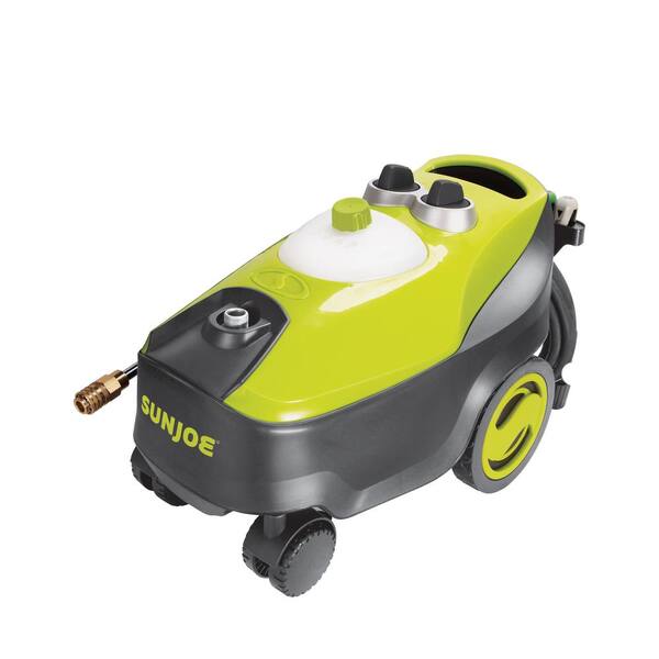
There are several factors that determine which components to use on a pressure washer. In choosing an unloader you must consider the intended purpose, operating conditions, and additional accessories. Doing so will help ensure that the unloader will last and give you the intended results.
A basic pressure washer system consists of a drive, pump, regulator/unloader, hose, gun, wand, and a nozzle. The motor and pump convert horsepower to water flow to be delivered to the nozzle. Ultimately, the pressure in the system is created at the nozzle as water is forced through the orifice, which is controlled by the unloader. The unloader regulates pressure by either sending water to the nozzle or to bypass, depending on the setting of the unloader. The unloader acts like a traffic cop for the system by reacting to the system pressure and directing flow either toward or away from the nozzle. The more water through the nozzle, or the smaller the orifice, the more pressure you get. Conversely, less water through the nozzle or a larger orifice yields lower pressure. When the trigger gun is shut off the traffic cop puts up barricades and directs the flow through the detour we call bypass. Just like drivers on the road, the water circulating in bypass heats up if it is left there too long.
If the spring tension on the unloader is set low, pump pressure will be low because water is bypassing the nozzle. Increasing spring tension on the unloader will direct the flow to the nozzle and increase the operating pressure until there is no more flow to go to the nozzle. Can you guess what happens as the nozzle wears? A worn nozzle has an oversized orifice, so pressure will drop. What do you think happens if you adjust the unloader to a higher pressure setting with a worn nozzle? Remember that the unloader directs flow and that all of the flow was already going to the nozzle. In this case the operating pressure won’t increase but the amount of pressure it takes for the unloader to unload (traffic cop to put up the barricade) will.
To illustrate this idea: a low pressure setting is similar to everyone wearing roller skates, which can change direction very easily. As you increase the pressure setting the vehicles change from roller skates to bicycles to compact cars to buses to semi-trucks to freight trains. Imagine how hard it would be to stop or redirect a freight train compared to a compact car. This is the concept of pressure spike.A spike of pressure occurs when the unloader shifts modes (changes the direction of the water) from spraying to bypass. The spike pressure increases with the unloader setting until it becomes so great that damage begins to occur in the system—broken hoses, blown valve caps, leaking unloaders and so on. The spike pressure increases with the size of the ‘vehicle.’ The pipeline is the same and the flow is the same but the roller skates have become freight trains.
A proper unloader setting allows a small amount of continuous bypass (approximately 5% of total flow) to minimize the pressure spike and compensate for nozzle wear. As the nozzle wears, the 5% bypass will be redirected from bypass to the nozzle, allowing for a longer operational period before pressure begins to drop. As soon as a pressure drop is noticed the nozzle should be replaced. Once an unloader is set it should never have to be adjusted again unless there are modifications done to the system. There are two main types of unloaders used on pressure washing equipment—pressure trapping and flow-actuated. Pressure trapping unloaders react only to pressure in the system and give you instant pressure when you open the trigger gun. Flow-actuated unloaders react to both flow and pressure and give you a gradual build in pressure, sometimes referred to as a ‘soft start.’
Speaking in terms of intended use (application), a pressure trapping unloader is most appropriate when you are working on very durable surfaces, i.e. metal, concrete, brick, and asphalt. The sudden burst of pressure is less likely to damage these surfaces, but beware if you are working on a ladder as you could lose your balance. The flow-actuated style is appropriate for more delicate surfaces such as glass, wood, limestone, asphalt, plastic and so on. Also the soft start is better for working in precarious locations. The pressure builds gradually (over about one second) so you have a better chance to maintain your balance. Follow OSHA guidelines when working in elevated situations.
Operating conditions affect the unloader because water quality, temperature, and time in bypass effect life and reliability. The conditions affect both types of unloaders equally, inasmuch as poor water quality and extended bypass will wear them both out. Note that, on average, a pressure-trapping unloader is about one quarter the cost of a flow actuated to repair or replace. Another consideration is that the pressure-trapping unloader is more forgiving as it wears out. It will usually continue to operate to some degree even as it is near complete failure. Flow-actuated unloaders are slightly more finicky and may cease to function if they wear too much out of tolerance.
Finally, additional accessories such as more discharge hose, injectors, speed controllers, burners, telescoping wands and certain types of nozzles affect the unloaders differently. Pressure trapping unloaders respond to the pressure in the system. Additional accessories increase the apparent pressure and a pressure-trapping unloader will just bypass more water to regulate pressure. With a flow-actuated unloader, changes to the system can affect the operation of the unloader. Any line restriction downstream of the unloader will change the flow-actuated unloader’s operating characteristics.
Flow-actuated unloaders tend to be easier on the system overall. Pressure-trapping unloaders offer a little more reliability over flow-actuated, but once the system is set up correctly a flow-actuated unloader is as reliable, if not more so, than a pressure trapping.
Look at the ZK7 series unloaders and the Pulsar3 unloaders. Both are excellent in design and operation and will provide you years of use if properly installed and maintained.
This safety valve sits on the low pressure head on several models of the Ingersoll Rand T30 two stage pump. The safety valve has a maximum pressure rating of 80psi and threads into the pump with ¼” threads.
It is extremely rare that this safety valve goes bad. If the valve is blowing off, it is typically indicative of faulty valves on the inside of the pump. Bad valves will cause the safety valve to blow, as the inlet valve on the high pressure side does not close on the piston upstroke, therefore releasing high pressure air back through the intercooler into the low pressure head.
When the safety valve pops, you will need to replace the reed valves on the inside of your pump. Since this part was used on a number of different IR pumps, the valve/gasket kits for these models will vary. Please contact our parts department with your piston pump model number and we will be happy to find the correct valve and gasket kit for your compressor.
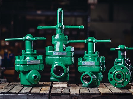
Over-pressurization is a looming factor that can cause significant damage to drills and machinery, making quality drilling pop-off valves a must. Drillmax, Inc. specializes in pop-off and relief valves, ensuring that your equipment is adequately protected during the course of your application.
In fact, since 1996, Drillmax, Inc. has specialized in a wide range of quality gate, float, relief and drilling mud valves. We have built strong ties working with a wide range of clients, including:
We our proud of the fact that our drilling pop-off valves are used all across the world in the industry, providing superior performance and longevity for the clients we service. As an aftermarket manufacturer of drilling mud valves and other components, we are able to offer superior service at a lower price point than OEM.
We offer drilling valve 2” aftermarket replacement parts, along with a wide range of other essentials that ensure your machinery and equipment runs efficiently and with minimal downtime. We offer:


 8613371530291