
diverter overshot packer supplier
Cameron diverters are fully customizable for your floater and jackup rig operations, respectively. Designed for reliable, efficient use, each system consists of a housing, outlet valves, running tools, controls system, diverter assembly, overshot packers, and storage skids.
The CF-A diverter supports up to 75.5-in rotary tables and has a hang-off capacity of up to 2,500,000 lbm. It uses a single annular packing element with a pressure rating up to 500 psi. The CF-A diverter features four hydraulic locking dogs that reduce hosing and simplify operation. It eliminates the need to secure hoses to the diverter assembly while providing hydraulic fluid for the operations.
The CF-B diverter supports up to 47-in rotary tables and is qualified up to 2,000 psi. Packers can be split and hinged to allow them to be changed out with pipe in the hole. J-slot type running tools are entirely mechanical and require no hydraulics.
A permanent diverter housing attached under the rotary table eliminates mechanical connections of the flowline and accessory lines, and expedites rig operations

The diverter assembly is the uppermost component of the riser system.It is not used to shur or seal the well completely, but to either direct the teturing drill fluit or control the blowout and surface layer gas, when encountering the gas, the diverter can close off around drillpipe or casing,and open the special direction vent line on board at the same time

Operating parameters is typically 750 psi closing pressure through 1-inch ID lines with a maximum wellbore pressure of 500 psi. Closing time is less than 10 seconds. Overboard lines should be as straight as possible in configuration to minimise erosion during diverting. Diverters can be connected directly to the conductor or drive-pipe or attached above the BOPs. On floating rigs the diverter is used to prevent trapped gas from reaching the rig floor after a kill operation.
In the past diverters have failed due to control system faults, human error, eroded and ruptured vent lines and blocked or plugged vent line valves. An important consideration is the proper maintenance and testing of the diverter system at regular intervals. Vent lines should be flushed and vent line valves should be function tested to ensure proper operation.
The MSP 500 permits open hole to be drilled full bore with diverter protection. It also permits the setting of large sized surface casing without removing the diverter. Thus the diverter is always ready for venting gas flows. The new design employs fewer parts and weighs less while at the same time decreasing the risk of malfunction. When using the MSP as a diverter during top-hole drilling, the primary purpose is to divert well flows away from the rig and personnel. This application avoids shutting in the well, but instead permits routing of the flow to a safe distance on the down wind side of the rig. Seal off is affected by hydraulic pressure applied to the closing chamber, which raises the piston unit radially inward into a sealing engagement. The MSP 500 however, is not well pressure assisted. If valves are to be added to the vent lines it is recommended they be full opening and designed to automatically open when the diverter is closed. This can be accomplished by using the closing pressure of the diverter as the pilot pressure for the valve, i.e., as closing pressure is applied to the diverter that same pressure causes the valve to open, thus assuring that there is no large well bore back-pressure build up.
A diverter is a safety system, which reroutes a well fluid flow away from the rig. Shallow gas is permitted to flow until depleted, or until the well is bridged over or killed by pumping in heavy mud. Ready during upper hole operations, a diverter is intended for use when there is a danger of penetrating a pressurised gas zone, while the casing shoe strength may not be sufficient to contain shut in pressures. Massive flows of gas and sand can quickly destroy a rig"s diverter system. Hydril incorporate integral valve functions and switchable target to minimise equipment and thereby decrease the risk of malfunction. Upward motion of one component, the piston, stops upward flow of the well fluid and opens the vent line. All that is required is one hydraulic signal from the remote panel, and since there is no waiting on valve functions a fast response is ensured.
At a time when the Offshore Equipment market is in turmoil, a new Manufacturer of Fixed Diverter Systems has emerged, providing New Technology, Patented in the United States, European Union and Singapore. AVERT-TEK LLC has focus on our customers (Drilling Contractors & Oil Companies) who require repairs, maintenance, and spare parts for their in-service equipment and also new equipment technology for the Diverter Well Control Systems.
Avert-Tek has compiled years of Diverter knowledge and capabilities, providing the current model KFDJ technology, and is introducing new technology in its Model DSP Diverter system. “DSP” stands for Diverter System Platforms and is focused on support of Jackup & Platform Shallow Water drilling.

Our FFZ75-3.5 diverters are designed and manufactured to SY/T 5127-2002 and ASME B16.47a-1998 standards. They feature a 29 1/2 bore size and rated to a 500psi working pressure (Tested to 800psi). The high quality tapered NBR packing element gives a significant storage volume and excellent sealing capability.
Cameron diverters are fully customizable for your floater and jackup rig operations, respectively. Designed for reliable, efficient use, each system consists of a housing, outlet valves, running tools, controls system, diverter assembly, overshot packers, and storage skids.
The CF-A diverter supports up to 75.5-in rotary tables and has a hang-off capacity of up to 2,500,000 lbm. It uses a single annular packing element with a pressure rating up to 500 psi. The CF-A diverter features four hydraulic locking dogs that reduce hosing and simplify operation. It eliminates the need to secure hoses to the diverter assembly while providing hydraulic fluid for the operations.
The CF-B diverter supports up to 47-in rotary tables and is qualified up to 2,000 psi. Packers can be split and hinged to allow them to be changed out with pipe in the hole. J-slot type running tools are entirely mechanical and require no hydraulics.
A permanent diverter housing attached under the rotary table eliminates mechanical connections of the flowline and accessory lines, and expedites rig operations
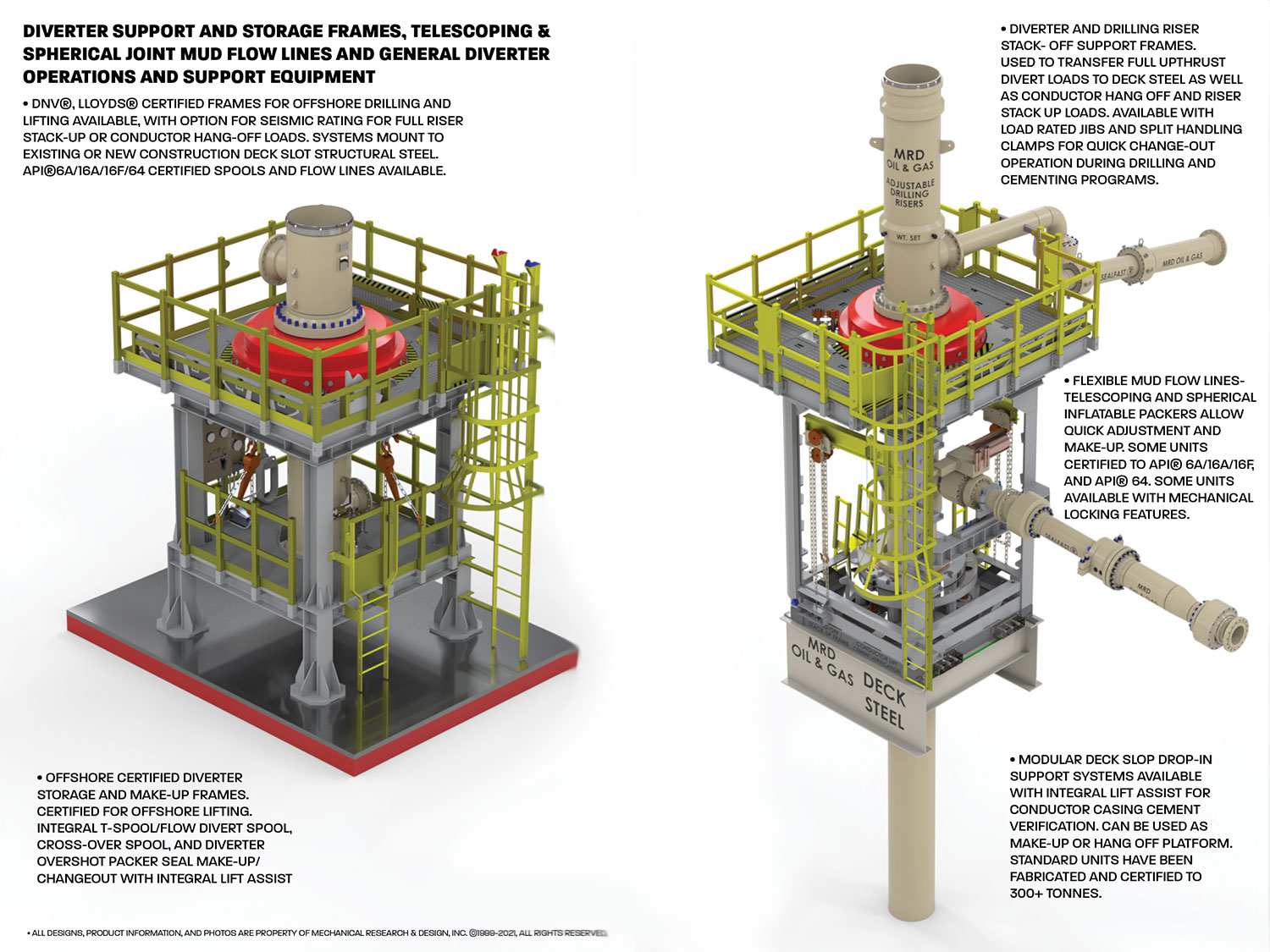
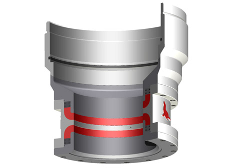
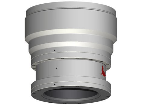
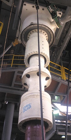
D eep well programs on the Arabian peninsula present unique challenges during the initial phase of drilling operations.Shallow gas pockets may be encountered that require managedwell bore control that is not currently available on existing land rigs.Utilizing feedback from the Saudi Arabian Oil Company (SaudiAramco), Dril-Quip, Inc. has developed the Arabian DiverterSystem (ADS) to address these challenges.The ADS (patent pending) is a portable diverter installed on theconductor and establishes a pressure-tight seal to enable controlleddiversion of any gas pockets that might be encountered. This divert-er system integrates three elements – the diverter housing, packingelements and an overshot spool-type connector – into a unitizedprotection device. The ADS incorporates safe, reliable field-proventechnology and performance features into a 500-psi-rated workingpressure design.Elastomer packers in the diverter close and seal around pipesuspended through the rig’s rotary table, isolating the rig floor fromfluids and gases flowing from the well bore. Large outlets locatedbelow the packers control and divert the flow to a designated area.Hydraulic controls for the diverter system are incorporated into therig’s BOP control system. Valves with hydraulic actuators aremounted on each of the diverter outlet lines to control the move-ment of fluids and gases through the system.The handling and test tools provided facilitate testing, operationand maintenance of the system.
FEATURES• Large-bore diverter accommodates 36" drift• A range of split insert packers provides well bore protection during both drilling and casing operations• Split packer design also facilitates running selected packer elements through a 37-1/2" rotary table• Split insert packer design simplifies installation via weight-set, lock-ring style auto-locking components; no hydraulics required• Overshot radial bolt connector features quick, easy make-up using standard impact wrenches• Overshot connector packer seal is hydraulically energized for reliable control of the well bore fluids• Engineered, designed and operated in accordance with applicable API industry standards• Adaptable to most land drilling rigs• Complete ADS diverter and valve system available from single source (Dril-Quip)
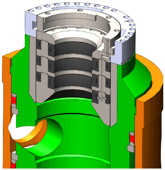
Packer Lockdown Ring Packer Load Ring Main Packer Assembly Main Packer Operation Port Main Body
10" Split Packer 18" Split Packer 27-1/2" Split Insert Packer 32-1/2" Solid Insert Packer Diverter Housing Retrieving Rod Assembly Handling Tool 10" Release Ring 18" Release Ring 27-1/2" Release Ring Tool Joint Pin Diverter Test Tool Diverter system valves not shown in illustration.
Main PackerThe Main Packer is housed in the main body of the diverter, andconsists of a tubular elastomer seal with metal rings molded oneach end. The one-piece packer is retained in the main body ofthe diverter by the packer lockdown, retaining and load ring.The Main Packer functions the insert packers when the diverteris closed. Hydraulic pressure deflects the packer toward the bore,which in turn deflects each of the insert packers installed. TheMain Packer is only removed during maintenance operations. 10" Split Insert PackerSolid Packers and Split Insert PackersThe Solid and Split Insert Packers land in the main body ofthe diverter and are designed to close and seal around variouspipe sizes. The packers consist of a tubular elastomer seal withmetal rings molded on each end. The Split Insert Packers aresplit in half so that they can be installed or retrieved whilepipe is suspended through the rotary table. A spring-loadedlockdown ring is bolted to the top of the packer and retains it inthe previously installed larger packer. Tapped holes in the topof the lockdown ring permit the swivel insert retrieving rodsto release the lockdown ring and recover the packer assemblywhen necessary. Each Split Insert Packer has two alignment slotslocated at the top of the packer to orient the packer assemblysuch that the split between the two halves is offset 90° from the 18" Split Insert Packersplit between the two halves of the previous size. All packers arerated to 500 psi.10" Split Insert PackerThe 10" Split Insert Packer incorporates J-slots on the ID tointerface with the Packer Handling Tool. The packer is operatedwith 925 psi and has a minimum closing diameter of 4-1/2".18" Split Insert PackerThe 18" Split Insert Packer lands in the 27-1/2" Solid Packerand is normally run with the 10" Split Insert Packer. The packeris operated with 850 psi and has a minimum closing diameter 27-1/2" Split Insert Packerof 9-5/8".27-1/2" Split PackerThe 27-1/2" Split Insert Packer lands in the main body of thediverter. It is operated with 750 psi and has a minimum closingdiameter of 26".32-1/2" Solid Insert PackerThe 32-1/2" Solid Insert Packer lands in the main body of thediverter housing. It is operated with 750 psi and has a minimumclosing diameter of 28". 32-1/2" Solid Insert Packer
4Operations Easy, simple Diverter Housing installation Test the Overshot and Diverter Packers The integral Overshot Packer is an adapter The integral Overshot Packer and Split spool that stabs over and provides a Insert Packers are tested with the Packer molded elastomer seal around the field-cut Handling and Diverter Test Tool. 36" conductor casing. A field-welded ring on the conductor OD provides a shoulder for the overshot spool radial bolt-type connector to contain any end-load forces in the event of a shallow gas encounter.
Step 1 Step 2 • Install conductor casing • Test system components with Packer • Weld ring on upper section of casing Handling and Test Tool • Install ADS Diverter System • Retrieve Test Tool • Make up Radial Bolt Overshot Connector • Energize Overshot Packer element
5Reliable managed bore protection Reliable managed annulus duringduring drilling operations casing installationThe Split Insert Packers can be installed The Split Insert Packers are retrievedassembled together with the Packer and the 32-1/2" Solid Packer isHandling Tool or individually with the installed to provide protection duringRunning and Retrieving Rod Assembly. surface casing installation.Hydraulic pressure applied to the MainPacker element functions the InsertPackers closed as required during drill-ing operations.
Step 3 Step 4 • Run drill bit • Run surface casing and cement • Reinstall Packer assembly • Nipple down ADS Diverter System • Drill out for surface casing • Nipple up BOP stack • Retrieve bit and bottom hole assembly

This invention rel~te~ in ~en~ra~ to ~iv~rt~rs ~nd blowout preventer systems for drillina ri~s, In particular, the invention relates to diverter and blow-out preventer systems and methods for use with bottom 5 supported o~fshore drilling rigs.
Diverter systems ror bottom supported off-shore drillina ri~s are known in which a diverter element is provided in the support housing attached to the support beams beneath the drilling rig rotary 10 table. Such diverter svstems have provided for a vent line and a flow line in the permanent housing beneath the rotary table. Such systems have required external valve systems in the vent line to assure that when the diverter in the permanent housing opens the fluid 15 system to the vent line, the flow may be directed away from the drilling rig. In such prior art systems, a spacer spool has been Provided beneath the support housing and a thirty (30) inch overshot connection has been provided between the spacer spool and the 20 thirty (30) inch outside diameter drive p~pe or structural casing.
Fatal and costly accidents have resulted ~rom thecomplexity of prior art diverter systems de-scribed above. Typical prior art diverter systems 25 have included an annulus closing device, external vent
and flow line valves, actuators, limit switches and sequenced controls. This complicated valving and pip-ing of the prior art has been further complicated by the inherent risks of man pulating loose packer in~
One problem with the prior art systems has involved the use of external valving in the diverter system. Valves which are external to the diverter unit not only add clutter to the diverter system and the rig configuration, it has also required multiple control functions which are required to operate perfectly. For example, the prior ~rt diverter svstem valves have required an actuatinq pressure signal that is regu-lated to a discrete pressure level different from the operating pressure level of the diverter unit. The need for separate and different control functions ex-ecuted in only one sa~e sequence has required separate pressure regulators and connecting components that are in different locations on the underside of the rig floor. Such a reauirement has invited mistakes and malfunctions.
rn addition to the problem of multiPle con-tr~l fllnctions, there has existed problems with crossed connections in prior art diverter systems. Misconnection o control lines can cause a valve to be closed when it should be open which could result in an explosion in the diverter or breach of the casinq~
Another problem of the prior art diverter systems has been exposure to the marine en~ironment of delicate parts such as hydraulic tubing and fittings, limit switches, mechanical linkages and val~e actuators.
Anoth~r problem oE prior ar-t diverter systems has been -the result of vent line blockage. Because the vent valve has been remote from the diverter unit it-5 Self, a stagnate space has existed at a critical loca-tion in the vent line. suildup of solids and cakinq of mud in such a dead space may cause the critically important vent line to be choked oEf. A restricted or shut-off vent line may cause a dangerous pressure lO increase while being called upon to divert.
Still another problem of prior art diverter systems for bottom supported rigs has been the require-ment of a high pressure valve in the vent line. Clo-sure of such a valve has enabled the diverter unit to s -- 4 ~
be converted to a blo~out preventer after sufficient casing pressure integrity has been established. How-ever, if this valve should inadvertently be closed during an attempt to divert, breach of the casing or 5 explosion of the diverter system could -threaten the safety of the rig ltself.
While many different types of valves have been used 10 in diverter systems, there has been no single valve that has been designed expressly for or is especially well suited to the particular appllcation of a di-verter system. Selection of the type, size and rating of such valves has been a vexing puzzle for designers 15 of rig valve systems which has been required to solve usually when a new drilling rig is being built.
Another ~mportant disadvantage of the prior art diverter systems has been the necessity to stop drilling operations and manipulate packer inserts to 20 facilitate annulus shut-off~ Such a necessity has not only been a time consuming task, it has presented vexy real hazards. One such hazard has be~n the problem of forgotten inserts. Often in the course of deter-mined efforts to drill ahead, fetching, installing and 25 latchin~ the packer insert is overlooked. Without such an insert there is no diverter protection. If the in-sert is in place, but not latched down in prior art di-verter systems, the packer insert is potentially a dangerous projectile.
A second problem resulting from the use of packer inserts has been the problem of open hole hazaxd about the pipe in the hole while the insert is being installed or removed. There has been no protection from the insert type diverter against uncontrolled 35 well ~luid flo~s. Such lack of protection has left a serious safety gap in the drilling operation.
Still another problem of the use of packer inserts in the prior art diverter systems has been the problem of forgotten removal. If unlatch and re-moval of the packer insert has been inadvertently over-5 looked before pulling drill pipe from the hole, cen-tralizers or the bottom hole assembly may be run into the insert, thereby endangering the drilling crew and equipment.
Still another problem of the use of packer 10 inserts in the prior art drilling systems has been the problem of exploding packers. If during testing~ the standard packer is not reinforced by an insert and/or a pipe in the hole, the hydraulic fluid pressure may cause the packer to explode, thus jeopardizing the 15 safety of the crew.
Perhaps the most important problem of the prior art diverter systems has been the inherent risk of pressure testing in-situ. Pressure testing of Prior art diverter systems has been accomplished by 2Q overriding the safety sequencing in the valves so that the vent line valve is closed simultaneously with closure of the annulus. Disastrous results have been e~perienced when the safety overriding mechanism has been unintentionally left in place when testing was 25 complete and drilling was resumed.
qhe present invention is designed to deal with the aforesaid problems and generally provides a system adapted ~or alternative use as a diverter or a blowout preventer for a bottom supported drilling 30 rig. The system is adapted for connection to a permanent housing attached to rig structure members beneath the drilling rig rotary table. The permanent housing has an outlet connectable to the rig fluid system flow line.
35 porting a drilling rig rotary table after structural casing has ~een set in a borehole, the method com-prising the steps of, lowe~ing through the rotary table a collapsed lower telescoping spool having a lower connection means at its lower end an an upper 5 connection means at its upper end, connecting the lower connection means at the lower end of the lower spool to the structural casing in the borehole/ horizontally moving the fluid flow controller having a housing wall outlet spool and adap~ed for alternative use as a 10 diverter or a blowout pre~enter to a position ~eneath the rotary table until the controller is substantially vertically aligned with the bore of said rotary table above and the lower telescoping spool below, raising said fluid flow controller until an upper end of said 15 controller is connected with said permanent housing, and stroking the lower telescoping spool out until the connection means at its upper end connects with a lower end of said controller.
With the diverter system of the present 20 invention the vent line is always open. Thus, the system has no valves or other obstructions in the vent line, there~y a~oiding the complexity of external valves, valve actuators and valve control functions.
valve, linkages~ limit switches, interconnecting con-trol lines, etc. which may be subject to the breakage of t 1 a ts crl lca p r Another feature of a preferred form~of the 5 invention provides a system having no stagnant space, a system in which the vent flow is immediately opened when the diverter system begins to divert fluid away from the well. Avoiding the stagnant space in the system, prohibits caking of solids that m~y obstruct 10 or shut-off vent flow.
Another aspect of the invention provides an annular packing unit in a diverter system thereby affording many important safety and operational ad-vantages such as the avoidance of providing inserts 15 when running in and pulling out of the hole during the drilling operation thereby avoiding potentially fatal mistakes of forgetting to fetch, install and latch down inserts. Such advantage also includes the ef-fect of rig time saved.
Another important advantage o~ a diverter system packing uni* is the ability to close on open bore thus providing ready assurance of safety in the event of excessive ~ell flow while there is no pipe in the hole and thereb~ eliminating a serious gap in 25 the safety of the drilling operation of prior art diverter systems.
Another importan-t advantage of the invention is to provide for safe testing with a packing unit which does not directly contact hydraulic fluid during ac-30 tuation, thereby eliminating the dangers of explodingpackers.
According to one embodiment of the in-vention telescoping spools are provided above and be-low the diverter blowout preventex unit thus providing 35 a ~ystem which is versatile and time-efficient. Fur-ther, it is contemplated that telescoping spools can be 5~
Figure l illustrates the apparatus. and method for installing a diverter BOP system between the per-manent housing 30 attached to support beams 14 beneath 35 the drillin~ rig floor. Rotary table 12 has a bore which may be opened to coincide with that of the per-5~
After the initial opening in the sea floor has been provided such as illustrated by borehole 4~, a struc-tural casing 48 is provided therein typically having 35 a thirty(30) inch outside diameter. A lower tele scopiny spool 40 is lowered via the bore of the rotary table 12 through the permanent housing 30 to the prox-im.ity of the structural casing 48. A handling tool (not illustrated) lowers the lower telescoping spool until 5 the overshot connection 50 at the lower part of the lower telescoping spool 44 engages the outer diameter of the structural casing 4~ providing an overshot connec-tion to it.
The system illustrated in Figure 2 may ad-25 vantageously be used as a diverter system during drill-ing through the structural casing 4$ for the purpose of providing the ho:Le for the conductor casing. Ac-cording to the invention, a failsafe system is provided re~uiring no external va]ving with all the inherent 30 advantages of simplicity, ruggedness and the ability to close about objects in the borehole or even close an open hole. The system is assured of diverting while closing the vertical flow path to the fluid system flow line in the event o~ a kick in the well.
Typically, the conductor casing 70 has an outside di-ameter of twenty (20) inches~ The conductor casing is 5 provided after the lower telescoping spool 40 has had its overshot connection disconnected from the struc-tural casing 48 and has been stroked upwardly and pin-ned until the conductor casing 70 may be installed within the structural casing 48 After the conductor 10 casing has been ins-talled, the top of i-t is cut off and an adapter spool 71 is provided having an upwardly fac-ing mandrel 72 which has an outside diameter equal to that of the structural casing. In other words, the mandrel 72 will typically have an outside diameter of 15 thirty (30) inches, similar to that of the struc-tural casing.
After the mandrel has been installed, the lower telescoping spool may be unpinned and stroked downward until the overshot connection 50 fits about the outside 20 diameter of mandrel 72 providing a fluid tigh-t con-nection. In this configuration of Figure 3, further drilling through the conductor casing 70 may continue in the diverter mode. In other words, the clamp 57, vent line 56 and blast deflector 58 may remain in place 25 if the flow controller 32 is to used as a diverter.
Figure 5 illustrates an alternative embodi-ment of the apparatus and method for installing a fluid flow controller or diverter/BOP system 32 to the per-manent housing 30. The permanent housin~ 3~ is at-tached to the support beams 14 beneath the drilling rig 35 floor. The bore of rotary table 12 is aligned with the permanent housing 30 thereby allowing tubular members to be inserted via the rotary table 12 and the permanent housing 30 to posi~ions below. A handling tool 80 is shown inserted through the bore of the rotary table 5 12 and releasably secured to the fluid flow controller 32.
A lower telescoping spool 40 is lowered via the bore of the rotary table 12 through the permanent housing 30 20 to the proximity of the structural casing 48. The lower telescoping spool 40 has an inner barrel 92 and an outer barrel 94. The overshot connector 50 at the lower part 44 of the lower telescoping spool 40 is en-gaged with the outer diame~er of the structural casing 25 48 pro~iding a lower connection means.
Turning now to Figure 7, an illustration of ~he low pressure blowout preventer system is presented after the conductor casing (not shown) similar to con-ductor casing 70 shown in Figures 3 and 4, has been run and cemented within the structural casing 48~ Typical-10 ly, the conductor casing has an outside diameter of twenty (20) inches. The conductor casing is provided a~ter the lower telescoping spool 40, as shown in Fig-ures 5 and 6, has had its overshot connector 50 diso connected from the structural casing 48 and has been 15 stroked upwardly and pinned until the conductor casing is installed within the str~ctural casing 48. ~fter the conductor casing has been installed, the top of the conductor casing is cut off and an adapter spool 71 and an upwardly facing mandrel 72 are installed~ The 20 mandrel 72 will typically have an outside diameter of thirty (30) inches, similar to that of the structural casing 48.


 8613371530291