
diverter overshot packer manufacturer
Cameron diverters are fully customizable for your floater and jackup rig operations, respectively. Designed for reliable, efficient use, each system consists of a housing, outlet valves, running tools, controls system, diverter assembly, overshot packers, and storage skids.
The CF-A diverter supports up to 75.5-in rotary tables and has a hang-off capacity of up to 2,500,000 lbm. It uses a single annular packing element with a pressure rating up to 500 psi. The CF-A diverter features four hydraulic locking dogs that reduce hosing and simplify operation. It eliminates the need to secure hoses to the diverter assembly while providing hydraulic fluid for the operations.
The CF-B diverter supports up to 47-in rotary tables and is qualified up to 2,000 psi. Packers can be split and hinged to allow them to be changed out with pipe in the hole. J-slot type running tools are entirely mechanical and require no hydraulics.
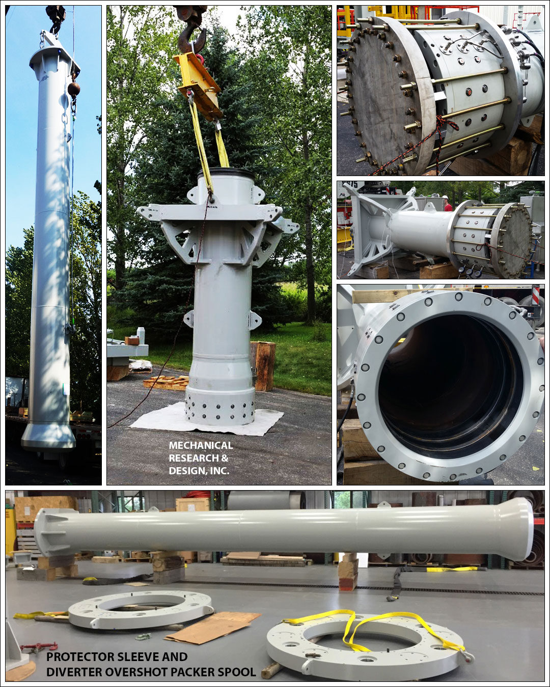
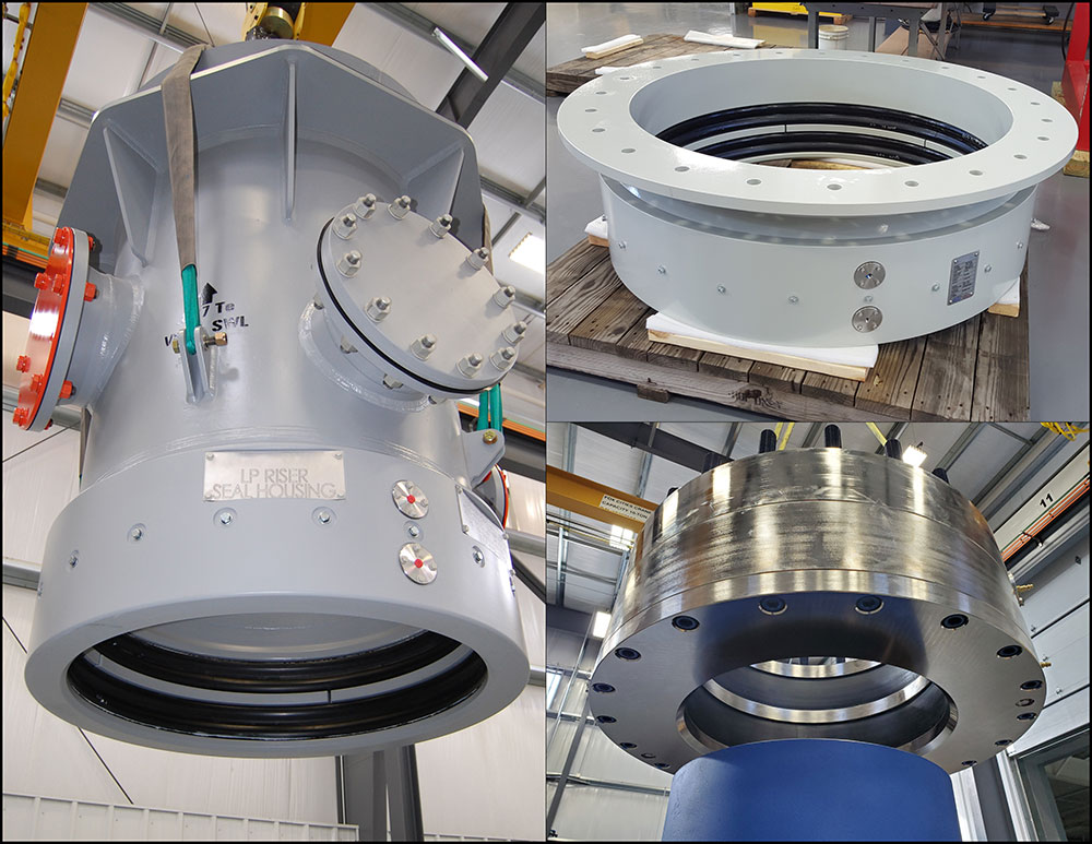
The RedSeal Dual Overshot Packer has been developed to provide a dual seal barrier in surface drilling systems used on jack-up and platform applications.
The RedSeal Dual Overshot Packer has been developed to provide a dual seal barrier in surface drilling systems used on jack-up and platform application. The system provides the operator with a primary and secondary seal system to mitigate potential environmental spills.
The system has been developed with a similar design philosophy to the RedSeal Packer system developed for drilling riser telescopic joints but does not include a facility for refill of the packer online as the seal element is a static seal and not subject to the dynamic motion associated to the RedSeal Packer system. Physically the RedSeal Dual Overshot Packer is shorter than traditional single packer systems allowing the system to be utilised in riser systems where stack-up heights are critical.
RedSeal Dual Overshot Packer can be supplied with a dedicated control system to monitor seal actuating pressure and (upon actuating pressure loss to primary seal element) switch automatically to the secondary seal, thereby minimising any environmental impact.
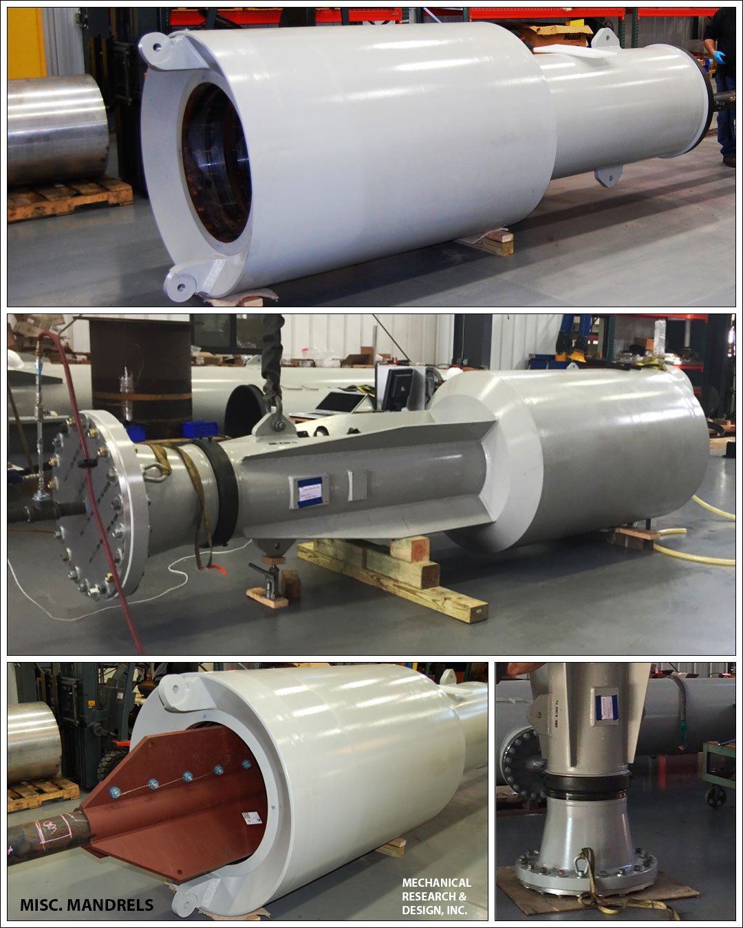
By utilizing our time-tested SEALFAST® inflatable and mechanical seals and packers, we are able to offer many flexible and configurable drilling stack solutions. Our products allow users to adjust for the height, angular alignment, and eccentricities in the drilling stack with unparalleled speed and efficiency. Our, fixed, telescoping, and spherical adjustment riser and mud flow line systems can be designed to accommodate down hole pressures from 5-2000 psig pressure ratings, with process mud temperatures of up to 300° F. Our active sealing technology continues to provide optimal sealing on mandrels and reducing faces, even if they corrode and wear over time, leading to lower maintenance costs
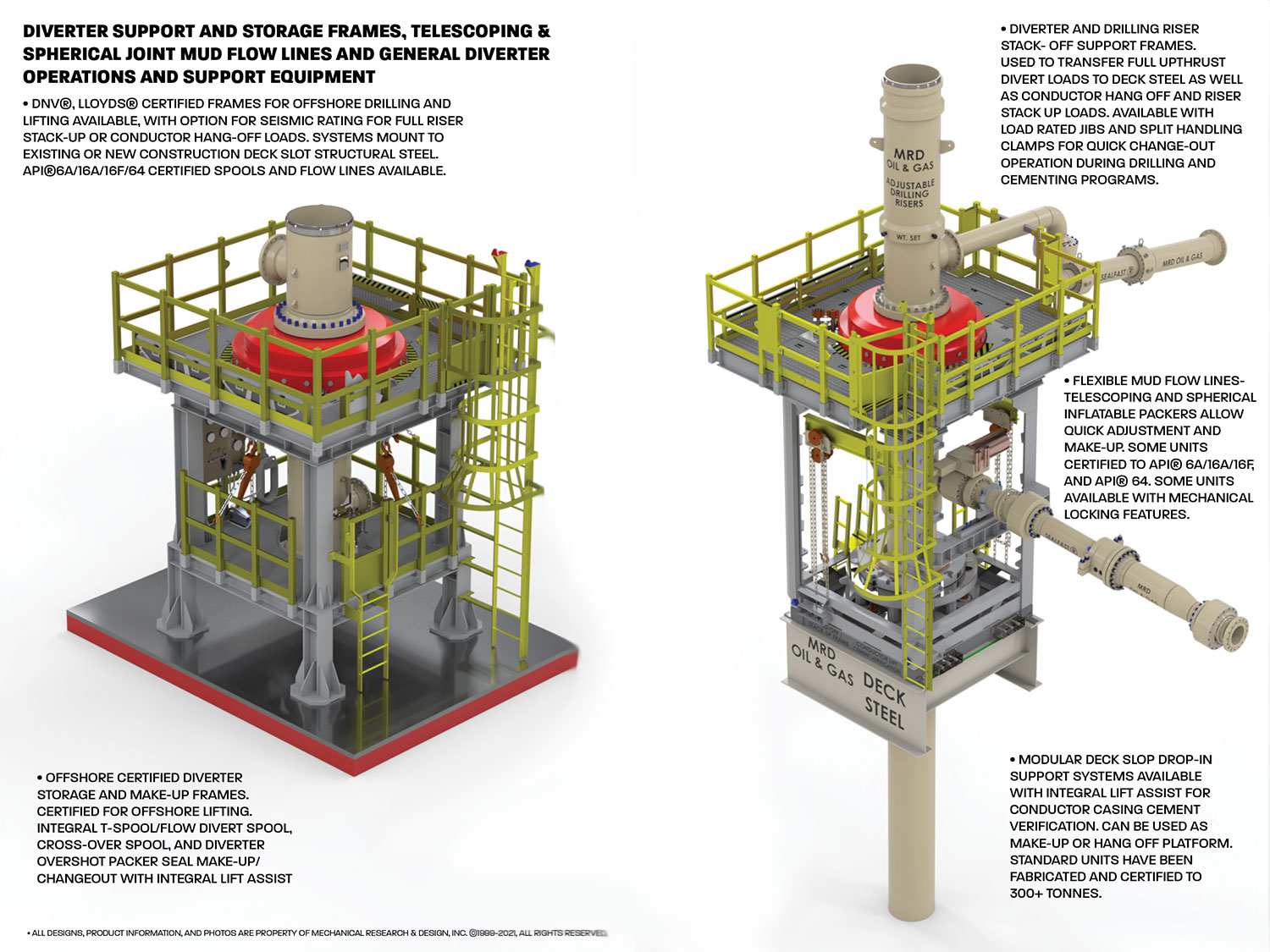
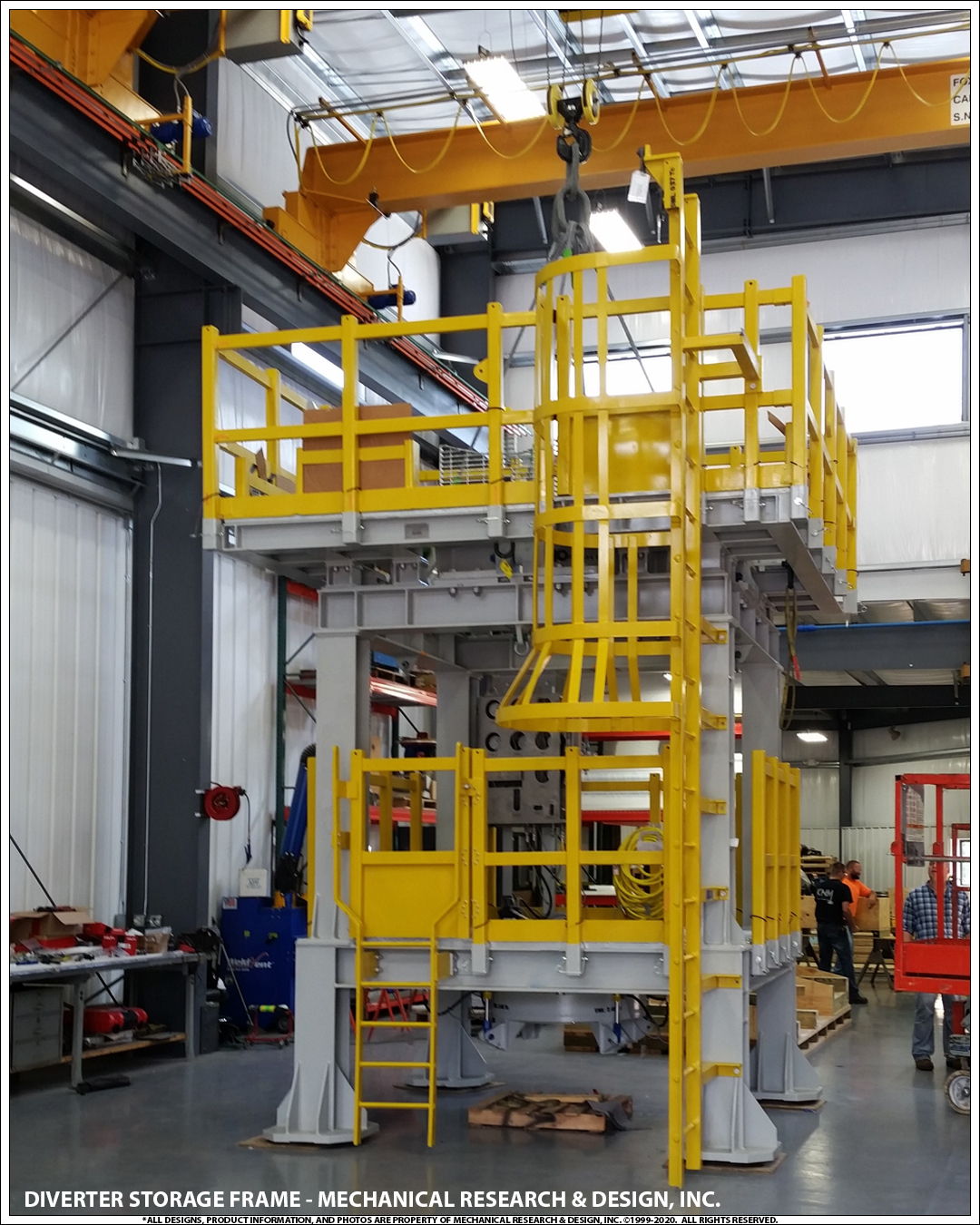
Mechanical Research & Design, Inc. designs and manufactures an assortment of fully certified Diverter and BOP support, restraint, lift, and storage equipment. Most units come certified for offshore portable equipment lifting and can include rated tie-down to deck structural steel for divert and upthrust events. Units can be adapted for integral nozzle load restraint for mud flow lines and safety rated work platforms. These frames are also used as make-up and load-rated hang-off platforms for surface drilling stacks.
Diverters are used with casing advancement systems when drilling through overburden. The diverters slip over the top of the casing to direct cutting, and fluids away from the hole. A hose can be connected to the diverter outlet to further direct the flow away from the hole. Please contact your Hole Products representative for additional product details.
At a time when the Offshore Equipment market is in turmoil, a new Manufacturer of Fixed Diverter Systems has emerged, providing New Technology, Patented in the United States, European Union and Singapore. AVERT-TEK LLC has focus on our customers (Drilling Contractors & Oil Companies) who require repairs, maintenance, and spare parts for their in-service equipment and also new equipment technology for the Diverter Well Control Systems.
Avert-Tek has compiled years of Diverter knowledge and capabilities, providing the current model KFDJ technology, and is introducing new technology in its Model DSP Diverter system. “DSP” stands for Diverter System Platforms and is focused on support of Jackup & Platform Shallow Water drilling.
The diverter assembly is the uppermost component of the riser system.It is not used to shur or seal the well completely, but to either direct the teturing drill fluit or control the blowout and surface layer gas, when encountering the gas, the diverter can close off around drillpipe or casing,and open the special direction vent line on board at the same time
A permanent diverter housing attached under the rotary table eliminates mechanical connections of the flowline and accessory lines, and expedites rig operations
Operating parameters is typically 750 psi closing pressure through 1-inch ID lines with a maximum wellbore pressure of 500 psi. Closing time is less than 10 seconds. Overboard lines should be as straight as possible in configuration to minimise erosion during diverting. Diverters can be connected directly to the conductor or drive-pipe or attached above the BOPs. On floating rigs the diverter is used to prevent trapped gas from reaching the rig floor after a kill operation.
In the past diverters have failed due to control system faults, human error, eroded and ruptured vent lines and blocked or plugged vent line valves. An important consideration is the proper maintenance and testing of the diverter system at regular intervals. Vent lines should be flushed and vent line valves should be function tested to ensure proper operation.
The MSP 500 permits open hole to be drilled full bore with diverter protection. It also permits the setting of large sized surface casing without removing the diverter. Thus the diverter is always ready for venting gas flows. The new design employs fewer parts and weighs less while at the same time decreasing the risk of malfunction. When using the MSP as a diverter during top-hole drilling, the primary purpose is to divert well flows away from the rig and personnel. This application avoids shutting in the well, but instead permits routing of the flow to a safe distance on the down wind side of the rig. Seal off is affected by hydraulic pressure applied to the closing chamber, which raises the piston unit radially inward into a sealing engagement. The MSP 500 however, is not well pressure assisted. If valves are to be added to the vent lines it is recommended they be full opening and designed to automatically open when the diverter is closed. This can be accomplished by using the closing pressure of the diverter as the pilot pressure for the valve, i.e., as closing pressure is applied to the diverter that same pressure causes the valve to open, thus assuring that there is no large well bore back-pressure build up.
A diverter is a safety system, which reroutes a well fluid flow away from the rig. Shallow gas is permitted to flow until depleted, or until the well is bridged over or killed by pumping in heavy mud. Ready during upper hole operations, a diverter is intended for use when there is a danger of penetrating a pressurised gas zone, while the casing shoe strength may not be sufficient to contain shut in pressures. Massive flows of gas and sand can quickly destroy a rig"s diverter system. Hydril incorporate integral valve functions and switchable target to minimise equipment and thereby decrease the risk of malfunction. Upward motion of one component, the piston, stops upward flow of the well fluid and opens the vent line. All that is required is one hydraulic signal from the remote panel, and since there is no waiting on valve functions a fast response is ensured.
* Some has an outer packer contained in the diverter housing and an insert packer for closure around various sizes of drill pipe. The outer packer is for use during running large sized surface casing.
* Diverters are available in 500 psi and 2,000 psi systems with a full range of insert packers. A hydraulic closing system is used to operate both the diverter and flowline/overboard valves.

This invention relates generally to subsea wells, and, more particularly, to improved diverter systems for use in drilling such wells from platforms above a subsea wellhead.
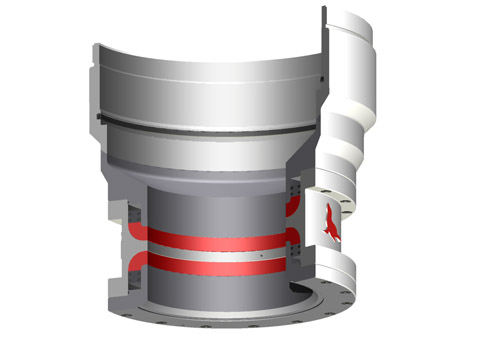
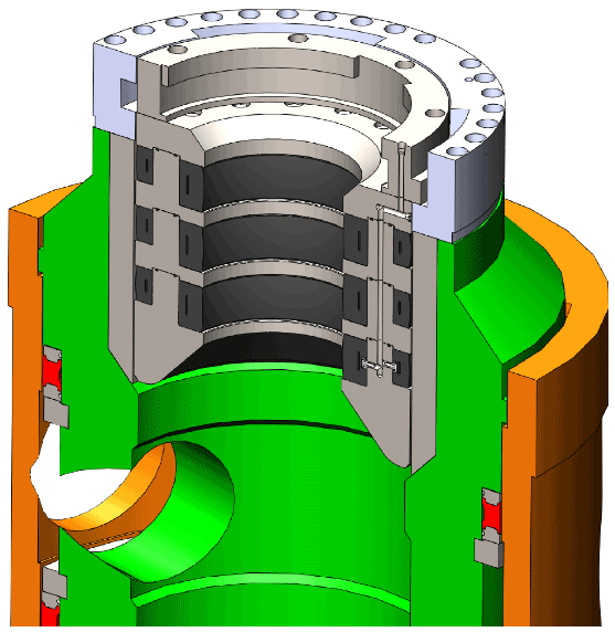
The purpose of such systems is to provide low pressure control over the well during the preliminary stages of drilling, and, for this purpose, the system includes a housing supported with its bore beneath the rotary table on the platform, and having one or more side outlets from the bore for connection with drilling mud return lines on the platform. A diverter assembly comprising a tubular body adapted to be lowered into a supported position in the bore has one or more ports aligned with each side outlet from the bore, and a spool suspended from the tubular body has an overshot packer at its low end which is lowered over the upper end of a conductor extending upwardly from the wellhead as the body is landed in the bore of the housing. More particularly, the tubular body carries means which seals between it and the housing bore to confine flow within the body into the side outlets, and packers are adapted to be lowered into and landed in the diverter body to seal about a drill string extending downwardly from the rotary table and through the spool leading to the conductor, whereby drilling fluid returns about the string are "diverted" into flowlines connected to the outlets for return to reservoirs from which the drilling fluid may be recirculated into the drill string.
The area beneath the platform and thus in and around the diverter housing is quite crowded with piping and other obstructions which often interfere with the flowlines. Hence, the operator might desire to divert the returning drilling fluid at a significantly lower level, perhaps 25-50 feet below the rotary table. This could be accomplished by providing the spool with fittings to which flowlines could be connected after the diverter body has been landed in the housing. However, this would be time consuming and expensive to perform, and, in order for the fittings to pass through the bore of the diverter housing, the spool diameter would have to be reduced, which in turn would reduce the size as the drill bit on the lower end of the drill string which is lowered through the spool.
The object of this invention is to provide a diverter system which is of such construction that the operator may, at his option, divert drilling fluid at a lower level without having to reduce the diameter of the spool and thus the size of the drill bit lowered through it.
These and other objects are accomplished, in accordance with the preferred and illustrated embodiment of the invention, by a diverter system which includes another or secondary housing having a bore therethrough and one or more side outlets from the bore and adapted to be supported beneath the primary housing with its bore aligned with the bore of the primary housing, when so supported, and in which the spool suspended from the diverter assembly body includes a tubular member intermediate its ends for fitting closely and landing within the bore of the secondary housing and having one or more ports therethrough, each adapted to be aligned with a side outlet in the secondary housing, when so landed, and means thereon for sealing with the bore ,of the secondary housing to confine flow within the member into the side outlets. More particularly, the bore of the secondary housing is essentially as large as that of the primary housing so that a full sized drill bit may pass therethrough.
FIGS. 1A, 1B and 1C are a vertical sectional view of a diverter system constructed in accordance with a preferred embodiment of the invention, with the diverter assembly installed within the upper primary housing in FIGS. 1A, the tubular member of the spool located within the bore of the secondary housing in FIG. 1B, and a packer at the lower end of the spool sealably engaged about the upper end of a conductor in FIG. 1C, the spool being interrupted along its length both above and below the tubular member.
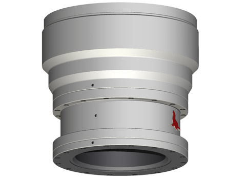
With reference now to the details of the above described drawings, the overall diverter system shown in FIGS. 1A, 1B and 1C includes an upper primary housing 10 supported from beams installed beneath a rotary table 12 (shown in broken lines). As previously described, the rotary table is located on the offshore platform, which may be located on fixed legs or may be of the jack up type. The system 10 further includes a lower secondary housing 13 supported a substantial distance beneath the primary housing, a diverter assembly 14 installed within the housing 10, and a spool 15 suspended form the diverter assembly for extension through the secondary housing. Thus, the spool 15 includes a sub or tubular member 16 intermediate its upper and lower ends for fitting closely and landing within the secondary housing 13, and an overshot packer 17 on its lower end sealably engaged about the upper end of a conductor 18 which, as previously described, extends upwardly from the subsea wellhead (not shown).
As best shown in FIG. 2, the diverter assembly 14 includes a tubular body 22 adapted to fit closely within the bore 20 of the housing and having a shoulder 23 thereabout for landing upon a seat 24 within the bore above the side outlets 21. More particularly, the tubular body has ports 25 therethrough which, when the diverter assembly is landed in the primary housing, are aligned with the side outlets 21, and seal rings 26 carried thereabout the tubular body for sealably engaging bore 20 above and below the side outlets to confine flow from within the body into the outlets.
As previously described, and as well known in the diverter system art, the diverter assembly 14 also includes means for sealing about a drill string (not shown) which extends downwardly through the rotary table and which has a bit at its lower end for drilling a wellbore beneath the subsea wellhead. As shown, this sealing means includes an outer inwardly inflatable rubber sleeve 31 which is inwardly contractible in response to the supply of fluid pressure to the outerside thereof through ports 32 in the body. In addition, annular packer elements 33 and 34 are lowered into and installed within the sleeve 31 and one another, as shown in FIG. 2, and releasably locked down by latches similar to those described in connection with the tubular body 22 of the diverter assembly.
The number and size of the removable packer elements depends, of course, upon the size of the drill string. In any event, the purpose of the packer elements is to permit the innermost element 34 to form a low pressure seal about the drill string upon inflation of the bladder 31. This then permits well fluid within the annulus between the drill string and the spool to be diverted through the ports and into the side outlets 25 and thus into flowlines connected thereto when drilling fluid is to be diverted at the upper level.
As previously described, the member 16 is connected intermediate the upper and lower ends of the spool 15 and is of a size for fitting closely and landing within the bore 35 of the secondary housing in a predetermined rotational position. With the sub so located, the packer 17 at the lower end of the spool fits over the conductor, as shown in FIG. 1. Thus, the length of the upper end of the spool depends on the desired level of the secondary housing, while the length of the lower end of the sub is so selected as to ensure that the overshot packer fits about and seals about the upper end of the conductor. These of course are determinations which are made by the operator depending on the well conditions.
As in the case of the tubular body of the diverter assembly, the sub 16 has ports 37 therethrough to connect the bore of the sub, and thus the spool, with the side outlets 36. More particularly, with the sub in a landed position within the secondary housing, the ports 37 are aligned with the side outlets 36, and as in the case of the tubular body of the diverter assembly, seal rings 38 are carried about the sub 16 for sealably engaging the bore 35 of the secondary housing to confine the flow through the ports into the side outlets 36.
The normally expanded landing ring 41 and locking ring 46 and the normally retracted orienting pin 51 permit movement of the sub downwardly through the bore of the secondary housing during installation of the diverter system, whereby the operator is assured that the overshot packer is in place before he raises the sub upwardly to a position for landing on the ring 41. This is also useful in the event the secondary housing is initially supported just beneath the primary housing and mounted about the sub 16 as the spool is lowered through the primary housing to the desired level therebelow.
By way of example, an offshore drilling system typically includes a marine riser that connects a drilling rig to subsea wellhead equipment, such as a blowout preventer stack connected to a wellhead. A drill string can be run from the drilling rig through the marine riser into the well. Drilling mud can be routed into the well through the drill string and back up to the surface in the annulus between the drill string and the marine riser. Unexpected pressure spikes can sometimes occur in the annulus, such as from pressurized formation fluid entering the well (also referred to as a “kick”). Blowout preventers (referred to in the field as “BOPs”) and diverters are typical safety measures for addressing kick and other dangerous pressure changes.
Some embodiments of the present disclosure generally relate to a modular BOP control system for controlling an annular BOP, a diverter, and a ram BOP. The modular BOP control system can include a skid. The modular BOP control system can also include a group of modular units each having a frame that is mounted on the skid. The group of modular units can include a main control unit module that controls and monitors the annular BOP. The group of modular units can also include a diverter valve module that controls and monitors the diverter. The group of modular units can further include a BOP valve module that controls and monitors one or more ram BOPs.
Certain embodiments of the present disclosure generally relate to a method. The method can include positioning a skid over a wellhead. The skid can include an upper surface having a plurality of module pockets. The method can further include lowering each of at least two modular units into a respective module pocket of the skid. The at least two modular units can include at least two of a main control unit module, a diverter valve module, a BOP valve module, an accumulator system module, and a BOP selector module. The method further includes, upon failure of any single modular unit, lifting the failed modular unit out of its module pocket and replacing the failed modular unit with a replacement modular unit.
As will be appreciated, the surface equipment 14 can include a variety of devices and systems, such as pumps, power supplies, cable and hose reels, a rotary table, a top drive, control units, a gimbal, a spider, and the like, in addition to the drilling rig. The stack equipment 18, in turn, can include a number of components, such as blowout preventers 21 and 22, that enable control of fluid from the well 12. Similarly, the riser equipment 16 can also include a variety of components, such as riser joints, flex joints, a telescoping joint, fill valves, a diverter, and control units, some of which are depicted in FIG. 1B in accordance with one embodiment.
Particularly, in the embodiment of FIG. 1B, the riser equipment 16 is provided in the form of a marine riser that includes a diverter 24, an upper flex joint 26, a telescoping joint 28, riser joints 30, and a lower flex joint 32. A marine riser is generally a tube (typically including a series of riser joints 30) that connects an offshore drilling rig to wellhead equipment installed on the seabed. In some instances, a floating drilling rig (e.g., a semisubmersible or drilling ship) is used to drill the well 12. To accommodate motion of the floating rig, the upper flex joint 26 can be connected to or near the surface equipment 14 and the lower flex joint 32 can be coupled to or near the stack equipment 18. Complementing the flex joints 26 and 32, the telescoping joint 28 compensates for heave (i.e., up-down motion) of the drilling rig generally caused by waves at the surface. In some instances, such as in embodiments involving jack-up rigs, flex joints 26 and 32 and telescoping joints 28 may be optionally omitted, and stack equipment 18 (including, for example, blowout preventers 21 and 22) can be provided at the surface (e.g., as part of surface equipment 14).
The diverter 24 operates to protect the drilling rig and other surface equipment 14 from pressure kicks traveling up from the well 12 through the marine riser. Such pressure kicks can be caused by pressurized formation fluids entering the well 12. The diverter 24 includes an annular preventer for sealing the fluid path from the well 12 when a pressure kick is detected. The pressurized fluid during a kick can be routed away from the drilling rig through one or more ports in the diverter 24.
Surface equipment 14 includes a control manifold with electrical and hydraulic controls for monitoring pressure and actuating one or more blowout preventers of the stack equipment 18 and the diverter 24. In legacy designs, the control manifold may be redesigned, reconfigured, and rebuilt for each jack-up specification or stack change, which is labor-intensive and skill-intensive work. Valuable rig time is consumed in redesign of piping and cabling at the site of the well.
In practice, stack equipment 18 typically includes a stack of blowout preventers of various types. A first type, a ram-type blowout preventer uses one or more pairs of opposing rams that press against one another to restrict flow of fluid through the blowout preventer. The rams can include main bodies (or ram blocks) that receive sealing elements that press together when a pair of opposing rams close against one another to seal large diameter hydraulic cylinders about the tubular in the event of a kick (or alternatively shear the tubular). By comparison, a second type of BOP, an annular preventer is a valve that is mechanically compressed inward to seal off a conduit (e.g., against a tubular) using a packer.
FIG. 2 is a schematic for a modular control unit (MCU) 34 that may be employed in surface equipment 14 of FIG. 1A in accordance with one embodiment. The MCU 34 includes a group of control modules supported in a skid 36, which will be described more fully below. The group of control modules can include a main control unit 38, a BOP valve unit 40, and a diverter valve unit 42. In other embodiments, the group of control modules can also or instead include an accumulator system module or a BOP selector module. The group of modules are positioned in the skid 36 such that the connections for power, communication, and hydraulic control are accomplished by placement of each module in position on the skid 36. In a particular embodiment, the connectors for power, communication, and hydraulic control may include hot-stab style connectors.
FIG. 3A is a schematic of skid interconnections in accordance with one embodiment. The skid 36 of FIG. 2 provides mechanical support to the control module units. In at least some embodiments, the skid 36 is a steel frame having three module pockets 58 that physically separate the modules from one another with a barrier, ridge or the like defining the module pockets 58. The edges of the module pockets 58 serve to align each module unit properly when placed on the skid 36 (typically using a crane or other lifting assembly). Each module pocket 58 is configured to receive one of the modular units described herein. Each module pocket 58 can include connections to a plurality of interconnects positioned similarly in the module pocket 58 to enable modular units to be swapped out for one another without re-routing any piping or cabling. Each module pocket 58 may include a valve or set of valves to couple to a given module positioned there. In the embodiment shown, module pocket 58C, configured to receive a main control unit module 38, includes a first valve 60 to couple the module unit positioned there to interconnect BOP stack system hydraulic line 44. Module pocket 58B includes a second valve 62 to couple the module unit positioned there to interconnect BOP stack system hydraulic line 44. Module pocket 58A includes a third valve 64 to couple the module unit positioned there to a diverter system hydraulic pressure line 48. Module pocket 58C also includes a fourth valve 66 to couple the module unit positioned there to interconnect to an adjacent BOP valve module 40 positioned in module pocket 58B.
FIG. 3B is a schematic of skid interconnections in accordance with one embodiment. As shown in FIG. 3B, the module pocket 58A, module pocket 58B and module pocket 58C each have three interconnects. Module pocket 58A is configured to receive a diverter valve module 42 (to be discussed further below), and includes connections to interconnects for a hydraulic return line 46 and a BOP manifold line 50, as well as a connection to the diverter system hydraulic pressure line 48. Module pocket 58B is configured to receive a BOP valve module 40, and includes connections to the BOP stack system hydraulic line 44 and the interconnects for hydraulic return line 46 and BOP manifold line 50. Module pocket 58C is configured to receive a main control unit module 38, and includes connections to annular BOP line 45 and the interconnects for hydraulic return line 46 and BOP manifold line 50. Rig air supply 52 is coupled to main control module 38, and a standardized hydraulic or pneumatic interconnect 54 between modules is also provided.
Main control module 38 unites the controls for the annular BOP and overall pressure gauges into a first module having the connections and functions separated from those relating to the diverter and ram BOPs. The main control module 38 can include controls for choke and kill valves, a pressure gauge for air supply pressure provided to the BOP control unit 34, a pressure gauge for BOP annular pressure, and a manifold regulator (i.e., regulating valve). FIGS. 4A-4D depict aspects of a main control unit module 38 in accordance with one embodiment. FIG. 4A provides a front view of the main control unit module 38. FIG. 4B provides a rear view of the main control unit module 38. FIG. 4C shows a side view of the main control unit module 38, and FIG. 4D is an example control panel on the main control unit module 38.
The control panel 80 shown in FIG. 4D is used in a particular embodiment, and the gauges and switches shown could be substituted for alternative functions. The functions on the control panel 80 are generally directed to the control and monitoring of the annular BOP (or pair of annular BOPs) of the stack equipment 18 of FIG. 1A. In the embodiment shown, the control panel 80 includes an air supply pressure gauge 86 (for indicating air supply pressure to the BOP control unit) and an annular BOP pressure gauge 88. The pressure gauges 86 and 88 may be ergonomically positioned near the top of the control panel 80 (e.g., about eye-level). Choke valve switches 90 and kill valve switches 92 (e.g., manual levers for control valves) are provided for controlling choke and kill line valves. The control panel 80 also includes hydraulic supply flowmeter gauges 94, for maintaining a view of the flow of hydraulic fluid to the annular BOPs, as well as a hydraulic return flowmeter gauge 95, for maintaining a view of the hydraulic fluid return line. The control panel 80 further includes an annular BOP packer control switch 96 that activates the packer.
A diverter valve module 42 collects the controls for the diverter and pressure gauges relating thereto into a second module having the connections and functions separated from those relating to the annular and ram BOPs. In some embodiments, the diverter valve module 42 includes pressure gauges, one or more regulators, and a diverter panel. The pressure gauges of the diverter valve module 42 can include any combination of the following: a diverter accumulator pressure gauge, a diverter manifold pressure gauge, a diverter packer pressure gauge, a diverter system pressure gauge, an overshot packer pressure gauge, and a flowline seals pressure gauge. The functions of the pressure gauges are self-explanatory and readily identifiable by one of ordinary skill in the art. A regulator of the diverter valve module can include one or more of a diverter manifold regulator, an overshot packer regulator, and a flowline seal regulator, each of which are readily known by function to one of ordinary skill in the art.
FIGS. 5A-5D depict aspects of a diverter valve module 42 in accordance with one embodiment. FIG. 5A provides a front view of the diverter valve module 42. FIG. 5B provides a rear view of the diverter valve module 42. FIG. 5C shows a side view of the diverter valve module 42 and FIG. 5D is an example diverter panel 108 on the diverter valve module 42.
Turning to FIG. 5A, components of the diverter valve module 42 are contained within a steel module frame 72. In the module frame 72, a diverter regulator 112 is provided, as well as a bank of valves 110. The diverter regulator 112 may include any combination of the following: a diverter manifold regulator (as shown), an overshot packer regulator (not shown), and a flowline seal regulator (not shown). Regulators may be selected from commercially available valves used to regulate the relevant pressure, as well established in the art. The removable bank of valves 110 may be reserved as spare, in an embodiment, for customization of the diverter valve module 42 to a particular rig. Alternatively, the bank of valves 110 may be dedicated to particular functions.
As in FIG. 4A, the module frame 72 includes a lifting assembly 78. The diverter valve module 42 further includes a diverter panel 108 that provides controls such as various switches, valves, and gauges, which will be discussed more fully below. In addition to the diverter panel 108, various gauges are positioned for ergonomic and efficient monitoring of the diverter, including a diverter manifold pressure gauge 98, a diverter packer pressure gauge 100, a diverter system pressure gauge 102, and an overshot packer pressure gauge 104. The functions of the pressure gauges are self-explanatory and readily identifiable by one of ordinary skill in the art. Spare pressure gauges 106 can be included in the diverter valve module 42 in an embodiment, for customization to a particular rig. For example, spare pressure gauges 106 may optionally be used for a diverter accumulator pressure gauge or flowline seals pressure gauge.
In the rear view, FIG. 5B shows the rear of diverter regulator 112 and the rear connection-side of the bank of valves 110. The rear side of diverter panel 108 couples to a modular input/output unit 114 (including, for example, a commercially available valve island). The side view in FIG. 5C shows the modular input/output unit 114.
The diverter panel 108 is shown in FIG. 5D in greater detail. Diverter panel 108 is used in a particular embodiment, but the gauges and switches shown could be substituted for alternative functions. The functions on the diverter panel 108 are generally directed to the control and monitoring of the diverter of the riser equipment 16 of FIG. 1A. In the embodiment shown, the diverter panel 108 includes switches (e.g., levers of control valves) for the diverter functions including any combination of the following: a flowline seal 116, a flowline valve 118, an insert packer locking dog switch 120, test line valve 122, port overboard switch 124, starboard overboard switch 126, test line valve 128, diverter lockdown dogs switch 130, filling line valve 132, overshot packer seal switch 134, diverter packer switch 138, packer pressure switch 140, and overboard preselect switch 142. The functions of these switches are self-explanatory and readily identifiable by one of ordinary skill in the art. Diverter flowmeter gauge 136 indicates measured flow through the diverter.
The BOP valve module 40 places the controls for the ram BOPs and pressure gauges relating thereto into a third module having the connections and functions separated from those relating to the annular BOP and diverter. The BOP valve module 40 can include a second set of pressure gauges (separate from and in addition to pressure gauges found on the other modules), a set of ram control valves, and a BOP manifold regulator. The second set of pressure gauges of the BOP valve module comprises any combination of the following: a BOP accumulator pressure gauge, a BOP system pressure gauge, and a BOP manifold pressure gauge. The functions of the pressure gauges are self-explanatory and readily identifiable by one of ordinary skill in the art.
In the rear view, FIG. 6B shows the rear of BOP manifold regulator 144 and rear connection-side of the valves. The rear side of diverter panel 108 couples to a modular input/output unit 164 (including, for example, a commercially available valve island). The side view in FIG. 6C shows the modular input/output unit 164 and pipe interface 166 coupling from the rear of BOP manifold regulator 144 and the valves to the top of BOP valve module 40. In an alternative embodiment, the pipe interface 166 can couple from the rear of BOP manifold regulator 144 and the valves to the rear side of BOP valve module 40.
Our FFZ75-3.5 diverters are designed and manufactured to SY/T 5127-2002 and ASME B16.47a-1998 standards. They feature a 29 1/2 bore size and rated to a 500psi working pressure (Tested to 800psi). The high quality tapered NBR packing element gives a significant storage volume and excellent sealing capability.


 8613371530291