
diverter overshot packer factory
Cameron diverters are fully customizable for your floater and jackup rig operations, respectively. Designed for reliable, efficient use, each system consists of a housing, outlet valves, running tools, controls system, diverter assembly, overshot packers, and storage skids.
The CF-A diverter supports up to 75.5-in rotary tables and has a hang-off capacity of up to 2,500,000 lbm. It uses a single annular packing element with a pressure rating up to 500 psi. The CF-A diverter features four hydraulic locking dogs that reduce hosing and simplify operation. It eliminates the need to secure hoses to the diverter assembly while providing hydraulic fluid for the operations.
The CF-B diverter supports up to 47-in rotary tables and is qualified up to 2,000 psi. Packers can be split and hinged to allow them to be changed out with pipe in the hole. J-slot type running tools are entirely mechanical and require no hydraulics.
Diverters are used with casing advancement systems when drilling through overburden. The diverters slip over the top of the casing to direct cutting, and fluids away from the hole. A hose can be connected to the diverter outlet to further direct the flow away from the hole. Please contact your Hole Products representative for additional product details.
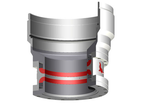
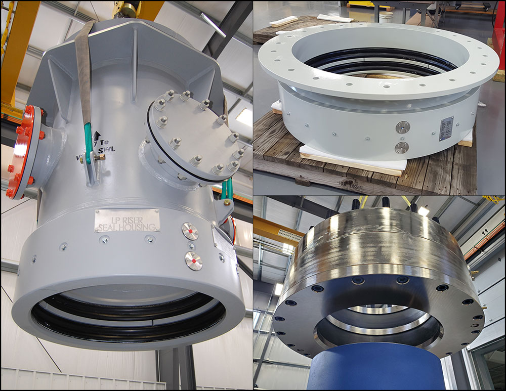
The diverter assembly is the uppermost component of the riser system.It is not used to shur or seal the well completely, but to either direct the teturing drill fluit or control the blowout and surface layer gas, when encountering the gas, the diverter can close off around drillpipe or casing,and open the special direction vent line on board at the same time
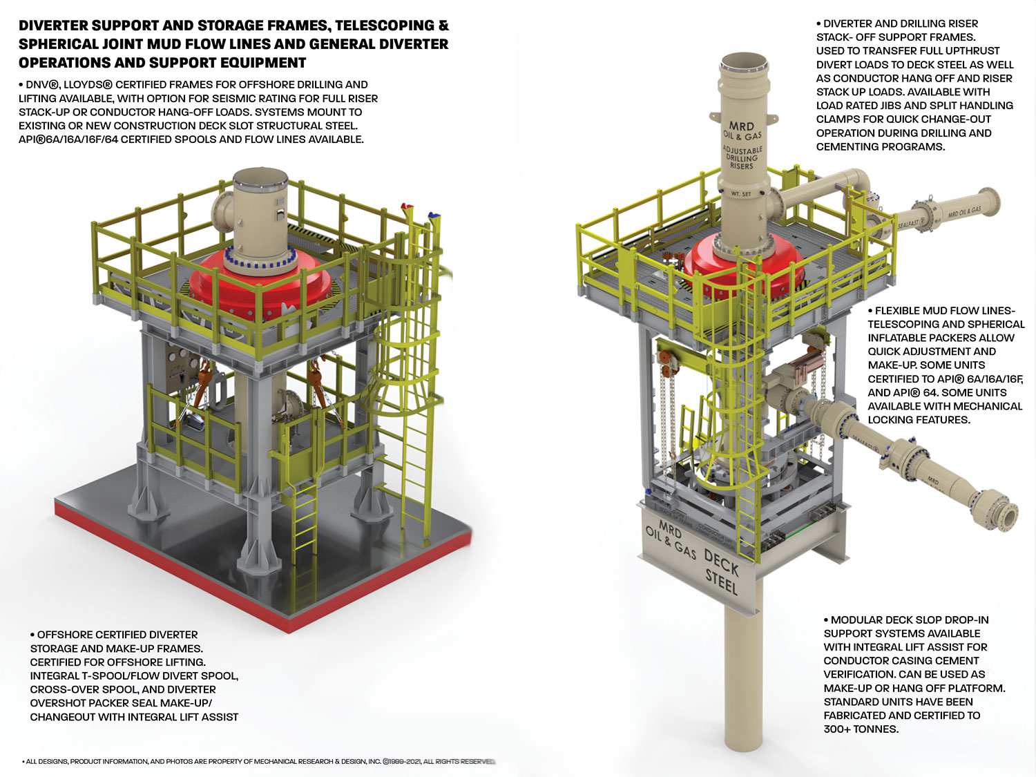
By utilizing our time-tested SEALFAST® inflatable and mechanical seals and packers, we are able to offer many flexible and configurable drilling stack solutions. Our products allow users to adjust for the height, angular alignment, and eccentricities in the drilling stack with unparalleled speed and efficiency. Our, fixed, telescoping, and spherical adjustment riser and mud flow line systems can be designed to accommodate down hole pressures from 5-2000 psig pressure ratings, with process mud temperatures of up to 300° F. Our active sealing technology continues to provide optimal sealing on mandrels and reducing faces, even if they corrode and wear over time, leading to lower maintenance costs
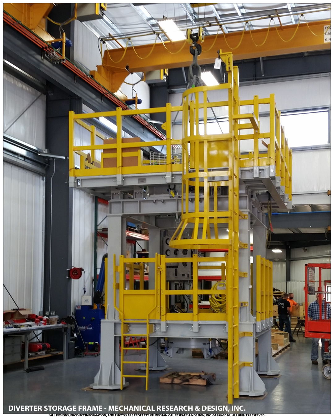
Mechanical Research & Design, Inc. designs and manufactures an assortment of fully certified Diverter and BOP support, restraint, lift, and storage equipment. Most units come certified for offshore portable equipment lifting and can include rated tie-down to deck structural steel for divert and upthrust events. Units can be adapted for integral nozzle load restraint for mud flow lines and safety rated work platforms. These frames are also used as make-up and load-rated hang-off platforms for surface drilling stacks.
Our FFZ75-3.5 diverters are designed and manufactured to SY/T 5127-2002 and ASME B16.47a-1998 standards. They feature a 29 1/2 bore size and rated to a 500psi working pressure (Tested to 800psi). The high quality tapered NBR packing element gives a significant storage volume and excellent sealing capability.

Petroleum and natural gas industries — Drilling and productionequipment — Shallow gas diverter equipmentIndustries du pétrole et du gaz naturel — Équipements de forage et de production — Équipement déflecteurpour gaz de surfaceOGP Draft 113354
Foreword..............................................................................................................................................................v Introduction ........................................................................................................................................................vi 1 Scope ......................................................................................................................................................1 2 Normative references ............................................................................................................................1 3 Terms and definitions ...........................................................................................................................1 4 Diverter system equipment...................................................................................................................7 4.1 General purpose ....................................................................................................................................7 4.2 Findings of blowout reports .................................................................................................................7 4.3 Applications of diverter systems .........................................................................................................8 4.4 Design considerations — Land rigs and bottom-supported marine structures .............................8 4.4.1 General....................................................................................................................................................8 4.4.2 Types of annular sealing devices in use .............................................................................................8 4.4.3 Vent outlets ..........................................................................................................................................12 4.4.4 Diverter valves .....................................................................................................................................14 4.4.5 Diverter piping .....................................................................................................................................15 4.4.6 The control system ..............................................................................................................................18 4.4.7 Kill-line facility .....................................................................................................................................18 4.4.8 Additional functions for the diverter system ....................................................................................18 4.5 Design considerations — Floating rigs .............................................................................................18 4.5.1 General..................................................................................................................................................18 4.5.2 Annular sealing devices in use ..........................................................................................................19 4.5.3 Auxiliary diverter system equipment for riser drilling .....................................................................21 4.5.4 Diverter outlets and valves .................................................................................................................23 4.5.5 Diverter piping .....................................................................................................................................23 4.5.6 Control system .....................................................................................................................................24 5 Floating rigs — Specific aspects .......................................................................................................24 5.1 Use of the marine riser ........................................................................................................................24 5.2 Additional functions of the diverter system .....................................................................................27 5.3 Comparison of types of floating support ..........................................................................................27 5.3.1 Moored drill ships ................................................................................................................................27 5.3.2 DP drill-ships ........................................................................................................................................28 5.3.3 Semi-submersibles ..............................................................................................................................28 5.3.4 Conclusion ...........................................................................................................................................28 6 Preparation for shallow gas operations ............................................................................................30 6.1 Call for tender ......................................................................................................................................30 6.2 Important issues ..................................................................................................................................30 6.3 Pre-spud checks ..................................................................................................................................31 6.3.1 Diesel engines and electrical equipment ..........................................................................................31 6.3.2 Kick and loss detection.......................................................................................................................31 6.3.3 Offshore rescue ...................................................................................................................................31 6.3.4 Offshore cooling recommendations ..................................................................................................31 6.3.5 Offshore emergency-release requirements ......................................................................................31 6.3.6 Rig safety equipment ..........................................................................................................................32 6.3.7 Safety precautions ...............................................................................................................................32 6.3.8 Diverter system ....................................................................................................................................32 6.4 Pre-spud meetings ..............................................................................................................................33 6.5 Pre-spud drills ......................................................................................................................................34 6.6 Preparing the response to a shallow-gas flow .................................................................................34 6.6.1 General..................................................................................................................................................34 6.6.2 Reminders ............................................................................................................................................35
6.6.3 Basic well-control aspects ................................................................................................................. 357 Diverter system maintenance ............................................................................................................ 38 7.1 General ................................................................................................................................................. 38 7.2 Certification and recertification ......................................................................................................... 38 7.3 Diverter system piping ........................................................................................................................ 38 7.4 Manufacturer documentation ............................................................................................................. 39 Bibliography ...................................................................................................................................................... 40
Many past shallow-gas kicks turned into uncontrolled blowouts due to the failure of former diverter systems installed several decades ago. Failure is seen as a result of the system"s complexity, its lack of functional reliability and its inability to cope with the severe dynamic loads,
1 ScopeThis International Standard specifies requirements for the selection of the diverter equipment for rigs used todrill shallow-gas-bearing formations. It covers both onshore and offshore drilling operations, and considersalso the auxiliary equipment associated with floating rigs.
3.11control functioncontrol system circuit (hydraulic, pneumatic, electrical, mechanical, or a combination thereof) used to operatethe position selection of a diverter unit, BOP, valve or regulator
3.13diverterdevice attached to the wellhead or marine riser to close the vertical access and to direct any flow into a set ofvent lines and away from the drilling unit
3.18diverter systemassemblage, comprising an annular sealing device, flow control means, vent system components and controlsystem, which facilitates closure of the upward flow path of the well fluid and opening of the vent to theatmosphere
3.54subsea diverterseabed diverterset-up of equipment attached to the bottom of the marine riser and connected to the 762 mm (30 in) subseawellhead housing, designed to close the well in case of shallow-gas influx and to direct it through two subsealateral vent outlets
3.58telescopic joint packertorus-shaped, hydraulically, pneumatically or mechanically actuated, resilient element between the inner andouter barrels of the telescopic joint which serves to retain drilling fluid inside the marine riser
The diverter system is designed to permit the drilling crew to blow down shallow-gas accumulations downwindof the rig. Until a sufficient casing length has been set to allow a well to be shut-in during a kick, the divertersystem is the only line of defence, and is only expected to contain the hazard temporarily, although as long aspossible.
The diverter system is not intended to be a well-control device. It simply allows the flow to be diverted in asafe manner in order to allow enough time to attempt regaining primary control of the well and, should thelatter fail, enough time for proper evacuation of the drilling crew or for proper move-off of the drilling unit fromthe location (floating rigs), until the flow stops due to gas accumulation blow-down, hole bridging, holecollapse, etc.
Blowout inquiries have concluded that the original designs underestimated the fact that shallow-gas blowoutsproduce huge amounts of gas, together with abrasive solids, flowing at very high speed, producing severedynamic loads, and eroding and destroying many parts of the existing diverter systems.
Statistics obtained in the 1990s in Norway have shown that 54 % of shallow-gas blowouts caused severedamage or total loss of the drilling structure and support, due to the failure of the diverter system.Unfortunately, many lives were lost during those dramatic events.
It is therefore of paramount importance to select suitable equipment able to function in a reliable and safemanner, i.e. able to operate whenever required under the worst possible conditions. Diverter equipment shallalso be able to cope with the prevailing dynamic loads and associated effects.
In the insert-type diverter assembly, the insert packing is latched in place into a diverter assembly, which inturn is locked inside the support housing. This housing provides two outlets, one for the mud returns to flowtowards the shakers, one for the diverted fluids to flow out through the vent line(s). The insert is removed priorto pulling or running the bottom-hole assembly (see Figure 1).
This set-up requires a conventional bag-type preventer and a drilling spool (or diverter spool) which aredirectly located on top of the first casing (conductor pipe, drive pipe). This set-up is therefore below the rotarytable and below the flow-line, unlike the insert-type diverter assembly (see Figure 2).
Key1 Bell nipple 6 Vent line2 Flow line 7 Diverter spool3 Fill-up line 8 Hydraulically operated full opening valve4 Annular packing element 9 Drive / Conductor pipe5 Standard bag-type preventer
insert-type packer usually closes fast (a few seconds), while the operation of the vent and flow- line valves takes much longer (> 40 s), hence imposing a sequencing system to prevent closure of the packer prior to proper operation of the valves;
The standard hook-up option eliminates the need for a flow-line valve, as the flow-line is located at the level ofthe bell nipple, well above the diverter set-up.
The use of an overshot packer, required for length adjustment below the diverter system, is also eliminated,hence removing a potential leak point at pack-off level. Conversely, this adjustment joint and its packer can beused without risk above the bag preventer, as it will not experience any gas flow pressure.
Another safe alternative is to use an integral diverter assembly, which integrates the diverter spool and theannular packing into a single piece of equipment.
In this system the motion of the annular piston is used, in one stroke, to first open the vent lines and then stopthe upward flow. The flow-line is located at the level of the bell-nipple, well above the integral diverterassembly, hence eliminating the need for a specific flow-line valve (see Figures 3 and 4).
Several types of valve are commonly associated with diverter systems: gate valves, ball valves, switchablethree-way target valves, knife valves, valves integral to the diverter unit and sometimes burst disks.
For insert-type diverter systems requiring actuation of valves on both shaker and vent lines, an interlocksystem shall prevent the diverter from closing before the valves are in the correct position (i.e. shaker valveclosed, vent-line valve open). This is of paramount importance with these systems, where the response timeof the insert packer is much lower than that of the shaker and vent-line valves [usually less than 10 s to closeon a 127 mm (5 in) drill pipe].
Actuators fitted to a diverter valve shall be sized to open the valve at least with the rated working pressure(WP) of the diverter system applied across the valve.
The safest and most reliable option is the integral diverter system (see Figures 3 and 4) in which the physicalneed for valves is eliminated. In such a system, the shaker and fill-up lines are located far above the divertersystem within the rig sub-structures, and do not require any shut-off valves.
Diverter piping shall consequently be sized and its layout designed such that the anticipated back-pressure,calculated with realistic gas flow rates, do not exceed the rated working pressure of the diverter system, donot exceed the design pressure of other equipment, and do not place undue pressure on the wellbore.
At the rig site location, the diverter vent-lines shall extend a sufficient distance in the most appropriatedirection from the rig to permit safe venting of diverted well fluids.
Consequently, the minimum required nominal internal diameter (ID) of diverter outlets and vent-lines shall be355,6 mm (14 in). The piping wall thickness shall not be less than 19,05 mm (0,75 in).
The diverter control system shall be designed and sized in accordance with API 16D:2005, Section 5.5. It shallcontain the minimum of functions. Preferably, a one-button or lever-activated function shall operate the entirediverter system.
A 38,1 mm (1½ in) hydraulic operating line should be used for diverter systems with a 1½ in NPT closingchamber port size. The hydraulic line for the opening chamber port may be 25,4 mm (1 in).
Many shallow-gas blowout reports have mentioned failures of the pneumatic control system used to operatediverter valves (e.g. failure to work as required when valves stems are blocked with solids). A pneumaticcontrol system shall therefore be avoided on rigs, if possible.
Each diverter system should incorporate a kill-line facility (including a check valve) to allow pressure-testing ofthe annular packing element closed on open hole, with no pipe in hole. This facility can also be used toperiodically flush the system clean.
Another advantage of a kill-line facility is to pump water through the diverter system during a gas-flow divertingoperation, in order to wet the gas and accordingly reduce the fire risk.
The use of a diverter system (alone or combined with a BOP set-up) should be considered on multi-wellplatforms, due to potential hazards such as collision with adjacent wells or surface-gas accumulations due topoorly cemented casings.
Though many parts of the diverter system are identical to those used on land rigs and bottom-supportedmarine structures, others are specific to floating units and are reviewed hereafter.
When drilling shallow-gas-bearing formations with a riser, two types of sealing device are used: the surfaceinsert-type diverter assembly and the subsea diverter.
By design, this system is basically similar to the system used on land rigs and bottom-supported marinestructures. The diverter support housing is permanently fixed to the drill-floor substructure below the rotarytable at the upper end of the marine riser system, and provides outlets for the shakers and for ventingpurposes. The diverter assembly is locked down inside the housing, and the insert packer is locked inside thelatter.
For floating supports, the possibilities to improve the surface vent-lines network and routing being substantiallyreduced, the subsea diverter system is a safer alternative. The basic set-up includes, from top to bottom: aflex joint, an annular BOP (or a shear ram unit), a diverter spool and a riser hydraulic connector (seeFigure 6).
If the subsea diverter option is selected, it is recommended to hook up a riser booster line above the upperclosing unit (bag or shear ram), to eliminate any gas which has entered the riser before complete well shut-off.An additional diverter system (e.g. the basic insert-type assembly) is required at surface to deal with this gasinflux (see also 4.5.2.3 and 5.2).
Prior to choosing this option, it is important to look carefully at the water depth and the type of support vesselwhich has been selected. Even after its transit through the water column, gas still represents a potentialexplosion and fire hazard, mainly as it concentrates in the moon-pool area. With gas being vented at seabedlevel and percolating up to surface, the subsea diverter is probably not the best choice with a drill-ship inshallow water depths.
Key Key1 539,7 mm (21 1/4’’) Flex Joint 1 539,7 mm (21 1/4’’) Flex Joint2 539,7 mm (21 1/4’’) Annular BOP 2 539,7 mm (21 1/4’’) Annular BOP3 539,7 mm (21 1/4’’) Diverter spool w/ integral valving 3 539,7 mm (21 1/4’’) Shear ram and 304,8 mm (12’’) outlets 4 539,7 mm (21 1/4’’) Diverter spool4 Guide structure 5 Outlet nozzle5 762mm (30’’) Hydraulic connector 6 762 mm (30’’) Hydraulic connector
NOTE The diverter is shown here in the drilling mode. When the diverter closes in case of gas influx, the piston movesupward, opening the flow path to the vent line while closing the flow path to the flow line.
Should surface diverting be considered as too hazardous (in particular if the integral diverter system is notavailable), the requirement for safe operation is to use the subsea diverter. Its use depends however on thewater depth at the drilling location, the virulence of reported local shallow-gas events, the type of supportvessel contemplated and the competence of the chartered drilling contractor.
The insert-type diverter system should only be used in conjunction with a subsea diverter or with a BOP stack,to circulate and vent out any gas trapped in the riser (see 5.2).
The same comments for land rigs and bottom-supported marine structures given in 4.4.3 and 4.4.4 apply tovent outlets and diverter valves for floating rigs.
On floating rigs (as for land rigs and bottom-supported marine structures), since the size and number of vent-lines have a great influence on surface and downhole hazards, two properly sized vent-lines shall be used.The minimum nominal ID of diverter outlets and vent-lines shall be 355,6 mm (14 in).
Key1 Flow selector always open2 Diverter with integral valve functions3 To Shale shaker4 To Vent lines5 To Starboard vent line6 To Port vent line
The diverter control system shall be designed and sized according to API 16D:2005, Section 5.5. Pneumaticcontrol systems shall be avoided on rigs working in shallow-gas-prone areas.
Each operating company has its own drilling policy with respect to using (or not) the marine riser while drillingshallow-gas-prone formations. The general mistrust of existing diverter systems on most floating rigs has ledsome operators to adopt a riserless approach. The following comments can be made.
Whatever the pros and cons of riser use, a preliminary careful and thorough review of the reliability andcapacity of the rig diverter system (see 4.5.2) and of the reliability and capacity of the emergency-releasesystem of the floating-support mooring lines can provide decisive criteria to assist in selecting the beststrategy.
Gas can inadvertently enter the riser when the BOP is shut-in on a kick. Gas can also enter the riser if the rams leak after the BOP is closed. Using the diverter system, the gas in the riser can be safely removed and diverted overboard,
After a kick circulation is completed, some compressed trapped gas can remain between the closed BOP and the choke-line connection. This gas will tend to migrate into the riser when the BOP is re-opened. Using the diverter system, this gas can also be safely removed and diverted overboard.
a competent drilling crew, having past experience in shallow-gas drilling, purposely trained and familiar with the diverter equipment and its proper testing, maintenance, and operation;
Prior to drilling a shallow-gas formation, all the diverter system components shall be inspected and tested toascertain proper installation and function. As a minimum, the following tasks shall be carried out.
Ensure that any fill-up line which can be exposed to the gas flow is protected with a check valve; this line and check valve shall have a WP equivalent to that of the diverter system.
d) Simulate loss of rig air supply to the diverter control system and determine effects, if any, on the diverter system, valves, and back-up systems.
On a routine basis, when in primary diverter service (no BOP installed), function tests should be performeddaily using the driller’s panel to verify that functions are operable. Fluid should be regularly pumped througheach diverter line during drilling operations to ensure that they are clear of obstructions at all times.
review all preliminary checks related to, among others, the diverter system, kick detection equipment, kill mud volumes, emergency power supply, safety, rescue and emergency equipment, emergency communication systems, mooring equipment if applicable, etc.;
All concerned personnel should therefore be familiar with the diverter system components and installation,and should be capable of reacting quickly and efficiently to potential situations requiring use of the diverter.
Any defect or problem with equipment or personnel identified during any of these pre-spud drills should beimmediately reported and dealt with before drilling is permitted to start. Thereafter, drills should be conductedat appropriate intervals to ensure personnel are capable of quickly and competently reacting to situationsrequiring use of the diverter.
If practically feasible, a tentative well kill should be attempted immediately with heavy kill mud and themaximum pumping rate available, after the diverter system has been activated, to try to stop the gas flowdownhole, prior to complete well unloading.
A schedule for routine inspection and maintenance of diverter systems equipment should be prepared andmaintained by the rig operating personnel. Specific guidelines for each diverter component or sub-systemshould be based on installation, operation and maintenance manuals provided by the equipmentmanufacturer.
During diverter function tests, observe all components of the diverter system including the diverter, valves, valve actuators, piping, and control panel to verify that there are no leaks in the system. If a leak is discovered, it should be repaired immediately.
All diverter equipment shall be maintained with original equipment manufacturer’s (OEM) genuine or approved spares and shall be operated and tested in accordance with that manufacturer"s recommended procedures. Major repairs, overhaul on and recertification of diverter equipment shall be performed either by the OEM or an alternative provider, but then only when approved by the OEM.
A visual inspection, a body-pressure test and a full-function test shall be carried out once a year on a diverter test stump at surface, in accordance with the manufacturer"s specification for such a test and witnessed by a certified third party. Results of the inspections and tests, including follow-up, shall be documented, providing full traceability and be part of the formal service history.
At least every five years, the diverter system components shall be inspected for repair or remanufacturing by the OEM or OEM-approved service provider. Upon completion of the inspection, the OEM shall provide a Certificate of Conformance (COC).
The wall thickness on all undesirable turns and bends (if any) in the diverter system piping should be checkedat least annually and after each use of the system to divert a well kick. Erosion of metal from the turns andbends can be severe if sustained flows of gas-associated solids are diverted through the system.
Installation, operation and maintenance manuals furnished by the manufacturers of the various components ofthe diverter system should be readily available for training, reference, and use by maintenance personnel.
A drilling mud diverter and method of use for horizontal drilling operations wherein drilling muds are diverted to a single portal of the bore where the drilling muds are recovered for removal or reprocessing, the mud diverter having a diverter unit with a central cylindrical core with enlarged end caps and an inflatable bladder mounted on the core, the diverter unit having a bypass passage through the unit blocked by a pressure relief valve that allows drilling muds blocked by the diverter unit to pass through the unit only when a preset pressure is reached; the method of use including the procedure for installing the mud diverter into an enlarged bore using the drilling pipe and removing the mud diverter using the drilling pipe, cables or other alternative equipment.
This invention relates to a mud diverter and a method of using a mud diverter in horizontal drilling. Horizontal drilling is primarily used as a means for installing a conduit for utility wires or pipeline for fluid transport where it is impossible or impractical to utilize simple trenching. [0001]
Where larger holes are drilled, the quantity of drilling mud generally requires that the mud be reprocessed on site. Once the pilot bore has opened the bore hole at both ends, it is either necessary to employ two mud reprocessing plants or to transport the spent drilling mud from one bore portal to the other by truck, pipeline or other means of conveyance. It is a primary object of this invention to divert the drilling mud and cuttings to one portal by utilizing a pneumatic diverter to block the mud flow to the opposite portal. [0005] SUMMARY OF THE INVENTION
This invention relates to mud diverter and method of operation for diverting drilling muds to a single portal in larger bore horizontal drilling operations. As the diameter of a horizontal bore is increased, the quantities of drilling mud required for the project become significant. The drilling mud diverter of this invention is positioned at an appropriate location in the bore and expanded to block the bore while allowing the pipe string to rotate and displace along its axis relative to the fixed position mud diverter. In the process of utilizing the mud diverter, drilling muds injected in the bore at the reamer are forced back around the pipe string through the enlarged bore to one of the two portals for recovery and reprocessing. [0006]
In the preferred embodiment and method, the expandable mud diverter is designed for a range of bore sizes, 24 inches to 60 inches. The mud diverter includes a cylindrical core having enlarged diameter end caps. The cylindrical core forms a sleeve on which an expandable bladder in the form of an annulus in secured. The enlarged end caps protect the bladder during installation and removal. An air supply is connected to the bladder enabling compressed air to be supplied to the interior of the bladder, which expands the bladder against the wall of the bore, fractionally locking the bladder in place. The mud diverter is designed with a central passage through the diverter that is sized to enable a pipe tail attached to the reamer to be drawn through the diverter. To accommodate the rotating pipe tail the end caps include fittings to support the rotating and displacing pipe tail On the side of the diverter where the drilling mud is deposited the diverter includes a swivel with flexible pipe seals for blocking passage of the drilling mud through the mud diverter. [0007]
In addition to the central passage, the pipe diverter includes a pressure relief conduit with a pressure relief valve allowing passage of mud through the diverter when the mud pressure rises to an unacceptable level. [0008]
In a typical operation, after the pilot hole has been completed and the reamer is attached, the bore is enlarged by a selected reamer which is pulled back through the bore hole. A pipe tail is attached to the reamer which follows the reamer back through the enlarged bore. The mud diverter is drawn into the enlarged bore by connecting to a tail pipe with a resalable connector that can position the diverter in the enlarged bore a sufficient distance from the portal to ensure that a firm seal is generated when the bladder is expanded. Typically, this distance is about one hundred feet. The mud diverter includes fastener anchors that connect the diverter to be withdrawn from the enlarged bore when the bladder is deflated and the drilling mud has been recovered. [0009]
FIG. 6 is a view of the diverter of FIG. 5 with an auxiliary pressure measuring unit and alternate locating device. [0017] DETAILED DESCRIPTION OF THE PREFERRED EMBODIMENTS
In FIG. 1, the mud diverter, designated generally by the reference numeral [0018] 10, is shown in a horizontal cross-sectional view. The mud diverter 10 of FIG. 1 includes a mud diverter unit 12 in combination with a swivel unit 14. The swivel unit 14 is utilized when the diverter unit 12 is drawn into an enlarged bore by a tail pipe attached to the drill pipe string as described in greater detail with reference to FIG. 4.
The diverter unit [0019] 12 has a rigid cylindrical core 15 and two enlarged-diameter end caps 16 and 18 that are bell-shaped. The end caps 16 and 18 each have a projecting neck section 20 and end flanges 22. The end flanges 22 couple to end elements 24.
In the cross sectional view of FIG. 1, the end elements [0020] 24 comprise guide elements that assist in guiding a trailing pipe tail or leading pipe string through the diverter unit 12 as described with reference to FIG. 4. In the diverter 10 of FIG. 1 equipped with the swivel unit 14, the diverter 10 is installed in a drilled bore with the swivel unit 14 located on the side of the diverter unit 12 that the drilling mud is supplied. The flange 22 on the end cap 18 opposite the mud supply is coupled to a ring flange 26 by a series of spaced bolts 28 with nuts 30 to secure a wear ring 32 that is preferably constructed of a wear resistant material such as brass or Delrin®.
In the configuration of FIG. 1, which includes the swivel unit [0021] 14, the diverter 10 is configured for passage of interconnected drill pipe through the diverter unit 14. The segments of the drill pipe are connected as the drilling process progresses. Each length of pipe typically has an end with an enlarged tool joint. The diameter of the tool joint is slightly greater than the diameter of the remaining pipe. The wear ring, therefore, is sized to accommodate the pipe diameter and the slightly enlarged tool joint. Sealing of the diverter unit 12 is provided by the swivel unit 14, which includes a swivel assembly 34 and a sealing assembly 36. The swivel assembly 34 has a collet flange 38 connected to the end flange 22 of the diverter unit 12 by a series of spaced bolts 40. The collet flange 38 functions in part to trap the wear ring 32 and to connect the threaded collet flange 38 to a threaded ferrule 42, which in combination with the flange 38 trap an enlarged portion 44 of a rotatable guide sleeve 46. To facilitate rotation, a pair of low-friction bushing rings 48 are positioned on each side of the enlarged segment 44 of the guide sleeve 46. A wiper ring 50 is secured to the end of the ferrule 42 by a series of small bolts 52 to prevent contamination of the rotatable swivel connection. The end of the guide sleeve 46 is threaded to interconnect with a threaded end flange 54 on the seal assembly 36. The seal assembly includes a series of spaced, flexible pipe seals 56 with rigid spacer rings 58 interposed between adjacent seals. The spacer rings 58 and an outer clamping ring 60 have an inside diameter substantially greater than the inside opening diameter of the seals 56, allowing the seals to flex over the slightly enlarged hub of displacing drill pipe. The seals 56, spacer rings 58 and end ring 60 are secured to the flange 54 by bolts 62 and nuts 64. The seals 56, as noted, are sized to slide over the drill pipe and tool joint at the end of each pipe segment and prevent pressurized drilling mud from passing into the sleeve 46 and diverter unit 12 during rotation and displacement of the pipe string.
It is to understood that modifications to the structure described may be made. For example, the swivel assembly [0022] 34 can be omitted and the seal assembly 36 can be directly connected to the end flange 22. For certain uses each end elements 24 may comprise blind flange 66 as shown in FIG. 3A, where the drill pipe does not pass through the diverter unit 12. Alternately, a reduction flange 68 with a small center hole 69, as shown in FIG. 3B, can be utilized when a pull cable is threaded through the diverter unit 12 instead of a pipe tail. Other modifications will be apparent as operating experience is gained during use of the diverter system of this invention.
To prevent the pressurized drilling mud from rupturing or damaging the reamed bore as reaming progresses with the diverter [0023] 10 in place, a pressure relief bypass assembly 70 is included in the diverter unit 12. The pressure relief bypass assembly 70 includes a projecting pipe stub 72 welded to one of the end caps here the end cap 16. Internally, the pipe stub 72 has a projecting threaded end 74 that connects by a threaded coupler 76 to the threaded end 78 of a bypass pipe 80 which passes through the diverter unit 12 and the opposite end cap 18.
Mounted on the other end cap [0024] 18 is a slip coupler 82 with a compressible seal 84 and compression nut 86. This arrangement allows the diverter unit 12 to be disassembled for repair or inspection. Alternately, a continuous pipe segment can be welded to the end caps 16 and 18, requiring removal of the weld if disassembly is required. The bypass pipe 80 connects to a bypass and blocking conduit 88 leading to the exit portal where a pressure relief valve 90 blocks passage of drilling mud unless a specified pressure is reached. This pressure may vary according to the size of the bore, the depth, the geology of the formation, the potential for rupture or bulging of the surface and other factors that are taken into account when mud flow to the entry port is blocked. As shown in the cross sectional view of FIG. 2, the end caps 16 and 18 each have an integral inwardly directed flange 92 which couples to a complementary inwardly directed flange 94 on each end of the rigid core 15. The flanges 92 and 94 are interconnected by bolts 96 and nuts 98. An annular expandable bladder 100 is seated on the core 15. The smaller diameter of the core 15 allows the collapsed bladder 100 to have an outer diameter equal to or slightly less than the diameter of the end caps 16 and 18. This prevents scuffing or damage to the bladder when the diverter is installed into or removed from the bore. The bladder 100 is fabricated from rubber, neoprene or other expandable material commonly used in pipe plugs.
A single diverter unit can be used in a range of bore sizes. In the unit shown, the diverter [0025] 10 is designed for bore sizes from 24 inches to 60 inches. To accommodate the through passage 102 for the drill pipe and the bypass passage 104 for the mud diversion in the smaller bore size, an arcuate cut-out 106 in the flanges 92 and 94 is necessary for situating the bypass pipe 80. For strength, a series of gussets 108 are added to the bell flanges 92 and to an internal extension 110 of the neck portions 20 of the end caps 16 and 18.
To install and retrieve the mud diverter [0028] 10, each end cap 16 and 18 have spaced eye brackets 120, preferably four eye brackets, welded to each of the end caps 16 and 18 for attachment of cable lines or chains. When the bore reaming is complete and the expanded bladder is deflated, the diverter 10 can be withdrawn by the cables attached to the eye brackets 120. Alternately, the mud diverter 10 can be withdrawn by pulling on the bypass and blocking conduit 88.
Referring now to the schematic illustrations of FIGS. 4 and 5, the method of using the diverter [0029] 10 in a horizontal boring operation is shown. A drilling rig 122 has an angled bed 124 raised to an appropriate angle for a drill 126 to direct drill pipe 128 at an entry portal 130 in an entry pit 132.
The entry pit [0030] 132 collects the return of drilling mud that is piped through the drill pipe 128 under pressure to a drill bit or the reamer 134, as shown in the schematic of FIG. 4. With the diverter 10 installed and inflated in the enlarged bore 136 through the exit portal 138, drilling mud is blocked from flowing to an exit pit 140 and is forced to return with the cuttings to the entry pit 132. At the entry pit 132, the fluid drilling mud and cuttings are pumped to a reprocessing plant 140, shown schematically in FIG. 4. The connected drill pipe 128 forms a pipe string 142 to the drill head 144 having the mounted reamer 134. Connected drill pipe 128 from the reamer 134 through the diverter 10 to the exit portal 138 forms a pipe tail 146.
In the schematic illustration shown, the diverter [0031] 10 is being drawn into the enlarged bore 136 by retracting the pipe string 142. The pipe string 142 is drawn back through a smaller pilot bore 148 by the drill 126, which is displaced on the angled bed 124 by a drive engine 150. The drill rig 122 is prevented from moving by tracks 152 on the rig and stakes 154 attached to the angled bed 124 which are inserted into the ground. It is to be understood that the drill rig 122 may differ in construction and the rig shown is an example of the type of rig used for the diverter system described.
The diverter [0032] 10 is drawn into the enlarged bore 136 by being connected to the pipe tail 146. In the system shown, a conventional elevator 156 is coupled to the pipe tail 146 and blocks the diverter 10 from slipping on the pipe tail. An elevator 156 is a releasable pipe clamp or shackle typically used in vertical drilling operations to suspend drill pipe or a pipe string during the procedure of connecting or disconnecting a length of drill pipe from a pipe string. As schematically shown in FIG. 5 the elevator 156 has a latch 158 attached to a small release cable 160. The latch 158 holds the clamshell-like, elevator together around a drill pipe 128 at an enlarged tool joint 162.
When the diverter [0033] 10 is located at a desired distance from the exit portal 138, usually a safe distance to prevent damage to the bore or surface when expanded, the bladder 100 of the diverter unit 12 is expanded as shown in FIG. 5. Using the release cable 160, the latch 158 is released, opening the elevator 156, which frees the elevator 156 allowing the elevator 156 to be withdrawn from the enlarged bore 136 by two cables 164 connected on each side of the elevator 156. The inflated diverter 10 is maintained in position by force of the inflated bladder 100 against the wall 166 of the enlarged bore 136.
Drilling mud supplied through the pipe string [0034] 142 discharged from the drill head 144 at the reamer 134 is blocked from passage around or through the diverter unit 12 and is forced to flow back around the pipe string 142 through the pilot bore 148 to the entry pit 132 where it is recovered, and, in larger operations, reprocessed on site.
In the event pressure of the drilling mud on the entry side of the diverter exceeds a predetermined pressure, usually because of blockage in the pilot bore [0035] 148, a pressure relief valve 90, set to a selected pressure, opens allowing the excessively pressurized drilling mud to pass through the diverter unit 12 via the bypass pipe 80 and through the bypass and blocking conduit 88. This conduit, usually a four inch steel pipe can lead to the exit pit or preferably to a standby collection vessel 168 schematically shown in FIG. 5.
In the usual situation with the diverter [0036] 10 installed and inflated, pressure in the bladder is maintained by a compressor 170 connected to the air pressure supply line 112 until the reaming operation is completed. The air pressure is then relieved, collapsing the bladder 100 allowing the diverter unit 12 to be extracted. The diverter unit 12 is installed with cables 172 attached to the eyelets 120 on the end cap 18. The cables 172 can be attached to a vehicle (not shown) for withdrawing the diverter 10. Alternately, the cables 172 can be attached to the pipe tail 146 by connecting the elevator 156 to a segment of pipe 128 at the exit portal 138 and pushing out the pipe tail 146 which in turn pulls out the deflated diverter 10. The elevator is removed and reattached as each segment pipe 128 is disconnected from the pipe tail 140 until the diverter 10 is retrieved at the exit pit 140.
Because the weight of the drill pipe [0037] 128 exerts substantial forces on the diverter 10 as the pipe tail 146 is displaced through the diverter 10, the diverter is fixed in position not only by the friction of the expanded bladder against the bore wall, but by anchoring the diverter 10.
This is accomplished by an anchor block [0038] 174 having a tee 176 for spanning the pipe tail 146 and cables 164 and 172 and mounting of inner stakes 178 and outer stakes 180 at the exit pit 140 preventing movement of the diverter 10 in either direction by advanced retracted drill pipe 128.
As noted, alternate methods of installing and removing the diverter [0039] 10 are facilitated by the design of the diverter unit 12. In the schematic illustration of FIG. 6, the eye brackets 120 on the side of the diverter swivel unit 14 are connected to short chains 182 connected to a steel ring collar 184. The collar 184 shown mounted over a vertically projecting nub 186 welded to the end of the reamer 134. In this procedure for positioning the diverter 10, a length of the bore from the exit portal 138 has been enlarged to the location for setting the diverter 10. The pipe tail 146 is advanced through the exit portal 146 to permit the collar 184 to be connected to the reamer 134 by placement over the nub 186. Without rotating the pipe string 142 the pipe string in drawn back through the bore until the diverter is positioned at the desired location in the enlarged bore. After inflating the bladder 100 and anchoring the diverter 10, the pipe string 142 is rotated and drawn, slipping the collar from the reamer 134 when the nub is downwardly directed. With the diverter 10 released, the enlargement of the bore by the reamer 134 continues to the entry portal 130.
As an auxiliary component to the diverter system. The diverter [0040] 10 in the embodiment of FIG. 6 includes a pressure measuring unit 190. The pressure measuring unit includes a compressible, cylindrical bladder 192 projecting from the end cap 16 adjacent the pipe stub 72 of the bypass assembly 70. The compressible bladder 192 is connected to a pressure line 196 through the diverter unit 12 as indicated in FIG. 2 to a pressure gauge 198 at or near the exit pit 140. This gauge 198 accurately indicates the pressure of the drilling mud and provides advance warning of activation of the bypass, allowing corrective action to be taken to avert potential activation.
Since horizontal drilling operations occasionally encounter the unexpected, the diverter system of this invention includes a mud diverter [0042] 10 having a rugged construction designed with components that provide options for locating and removing the diverter unit as the situation requires.
a pressure relief bypass assembly having a bypass through the end caps and cylindrical core that passes pressurized drilling mud through the diverter unit; and,
4. The drilling mud diverter of claim 3 wherein the expandable bladder when deflated on the cylindrical core has an outer diameter substantially equal to the diameter of the end caps.
6. The drilling mud diverter of claim 1 wherein the bypass assembly has a pressure relief valve that passes pressurized drilling mud through the diverter unit at a selected pressure.
7. The drilling mud diverter of claim 1 wherein the bypass assembly has a bypass pipe through the diverter unit connected to a conduit having a pressure relief valve for passing pressurized drilling mud through the diverter unit at a specified pressure.
9. The drilling mud diverter of claim 1 further comprising a swivel unit connected to the diverter unit, the swivel unit having a swivel assembly and a seal assembly.
11. In a horizontal drilling operation with drill pipe, the method of diverting drilling muds to one of two entry portals of a drilled bore using a mud diverter having an inflatable bladder comprising the steps of:
12. The method of claim 11 wherein the step of enlarging at least a part of the drilled bore to accommodate the mud diverter occurs after the step of connecting the mud diverter to the drill pipe.
13. The method of claim 11 wherein the diverter has a bypass passage through the diverter with a pressure release to block drilling mud from passing through the bypass unless a set pressure has been exceeded.
15. The method of claim 11 including the step of anchoring the mud diverter to prevent displacement of the diverter before continuing the displacement of the drill pipe to continue enlarging the bore.
19. The method of claim 18 wherein the diverter is connected to the drill pipe after the bore has been enlarged and the diverter is withdrawn by the step of displacing the drill pipe.

Another improvement in recent years is the “thru diverter” type wellhead. Such a wellhead allows for lower cost drilling on smaller or marginal formations. A thru diverter wellhead is particularly useful in “batch drilling,” which makes efficient use of a larger more expensive drilling rig to drill a number of wells. In batch drilling, after the drilling of a well is completed, the well may be capped, and the rig moved to another well location. The wells can be completed later by smaller more economical rigs.
There are several limitations with the existing thru diverter type wellheads. Although the wellheads may be placed in some larger diverters, there is minimal clearance since there are numerous housings and other protrusions typically welded to the wellhead"s exterior surface. Further, the exterior surfaces of the wellheads are uneven and non-uniform. Thus, the size of the wellhead that will move thru the diverter is limited. The wellheads will not fit at all in some smaller diverter housings. Further, such limited size wellheads only allow for the positioning of a single casing hanger with a single casing string.
There are also challenges to placement and operation of existing thru diverter type wellheads. There may be external threads on the exterior surface of the wellhead for attachment of the wellhead with other components of the stack. Further, there may be a groove on the exterior surface of the wellhead and a seal for sealing with other components of the stack. The seal, thread and/or the groove may be damaged either during placement of the wellhead or during an operation. An undamaged seal, thread and groove are necessary for the wellhead to maintain its maximum rated pressure after assembly of the stack. Damage to the seal, thread and/or groove will likely not be discovered until after the wellhead is permanently cemented in place with the wellbore, making replacement of the wellhead, at best, difficult. Time consuming and expensive field work may be needed to repair the damaged seal, thread and/or groove, with resulting lost time. The maximum pressure that the wellhead system may maintain may be compromised if a complete repair cannot be made. For example, if the groove cannot be completely repaired, then a lower pressure rated annular seal may be need to be used, which may lower the maximum rated pressure for the wellhead. The result may be a compromised plan for the well.
To protect the interior surface of the existing thru diverter wellhead during cementing and drilling operations, a removable protective sleeve has been positioned within the wellhead, which results in the loss of valuable rig time. Otherwise, cement or drilling fluid contaminants such as sand, rock and/or debris may damage the wellhead. Further, in some operations, there is an unmet need to bring tubulars, such as 4½ inch (11.4 cm) diameter casing or liners, completely back to the surface without disassembling the BOP stack. This would help solve some geological based drilling problems, as well as minimize rig time and mitigate a safety issue, as discussed above.
There remains a need for a thru diverter type wellhead that allows for the direct coupling of hydraulic control lines and related system to operate a downhole deployment valve and other downhole tools. It would be desirable to run the wellhead thru the diverter without housings and other protrusions extending from the exterior surface of the wellhead during installation so as to increase the size of the wellhead that may be moved relative to the diverter. It would further be desirable for such a wellhead to accommodate more than one casing hanger and casing string, and allow for tubulars to be brought back to the surface without disassembling the BOP stack. It would also be desirable to eliminate the need for a tubing head in certain circumstances. It would also be desirable to have a system and method that would protect the wellhead during its placement and operation. It would further be desirable to eliminate the need to install a temporary protective sleeve in wellhead during certain cementing and drilling operations. BRIEF SUMMARY OF THE INVENTION
A method and system are provided for positioning a wellhead in a diverter housing over the wellbore. Protrusions on the exterior surface of the wellhead are not initially installed or are removed before moving the wellhead thru the diverter. An overshot running tool may be used to place the wellhead while protecting the wellhead exterior and interior surfaces, grooves, threads, and seals. The overshot running tool allows for operations, such as drilling and cementing, after the wellhead is positioned with the wellbore, but before the running tool is removed. After the diverter is removed, an alignment pin housing may be attached with the wellhead, and an alignment pin used during the positioning or seating of the hanger to align the hanger side ports with the access openings in the wellhead for coupling of hydraulic control lines to the hanger. Hydraulic control lines may extend from the hanger to outside the wellhead and between the hanger and hydraulically operated tools. Other housings, such as those containing retainer pins, may also be attached with the wellhead after the diverter is removed. In one embodiment, the wellhead may be a single bowl that allows for the positioning of one hanger therein. In another embodiment, the wellhead may be an assembled “unitized” multi-bowl that allows for the positioning of two hangers therein. The hangers and tubulars may be positioned either from above or below the wellhead without removal of the BOP stack. Alternatively, the multi-bowl wellhead may be monolithic. The multi-bowl wellhead eliminates the need for a tubing head in certain circumstances. BRIEF DESCRIPTION OF THE DRAWINGS
FIG. 17 is a partial section elevational view of a diverter housing mounted with a wellbore tubular, a landing ring on the wellbore tubular, a support ring on the landing ring, and an overshot running tool within the diverter housing with a wellhead thereon coupled with a wellhead tubular.
FIG. 18 is a partial section elevational view of a diverter housing similar to the one shown in FIG. 17 mounted with a wellbore tubular, a landing ring on the wellbore tubular, a support ring on the landing ring, and an overshot running tool within the diverter housing with a monolithic multi-bowl wellhead thereon coupled with a wellhead tubular.
Turning to FIG. 17, first or diverter housing 470 is mounted on wellbore tubular 190A with lockdown bolts 477 and sealed with annular seals 478. Wellbore tubular 190A may be a 16 inch (40.6 cm) diameter conductor casing. However, other tubulars and sizes are contemplated. Conduit 670 with valve 672 is attached with tubular 190A. Conduit 502 with valve 506 is attached with bore 504 in housing 470. It is contemplated that there may be only one conduit (502, 670). It is also contemplated that one of conduits (502, 670) may be plugged. The top of overshot running tool 490 is threadably attached with running tool tubular 476. Overshot running tool 490 is also threadably coupled with casing head 202. One or more threads 496 on the interior surface of collar 492 of overshot running tool 490 are engaged with one or more threads 498 on the exterior surface of casing head 202.
Annular seal 500 on the interior surface of collar 492 seals with the exterior surface of casing head 202. Collar 492 is attached with body 494 of overshot running tool 490. Collar 492 may be welded to body 494. Other methods of attachment are contemplated. It is contemplated that collar 492 and body 494 may be substantially cylindrical in shape. Collar 492 and body 494 protect and cover groove 683A and thread 498 from cement and debris resulting from operations, as well as contact damage during movement. As shown in FIG. 10, annular seal 683 may be placed in groove 683A after running tool 490 is removed. Also, rim 206 may be threadably attached with thread 498 after running tool 490 is removed.
Returning to FIG. 17, collar 492 inside diameter is attached to and extends around a portion of the exterior surface 516 of body 494. The thicknesses of collar 492 and body 494 may not be uniform. Wellhead tubular 474 is threadably attached with casing head 202. Wellhead tubular 474 may be a surface casing. Concentric support ring 194 is positioned with wellhead tubular 474, and rests on landing ring 192. Casing head 202 rests on support ring 194. Flush plugs 480 are in the threaded bores (226, 227) of casing head 202. The longitudinal bore interior surface 510 of body 494 of overshot running tool 490 may be substantially even or flush with the interior surfaces of tubulars (474, 476). Exterior surface 516 of body 494 of overshot running tool 490 covers substantially all of the longitudinal bore interior surface 512 of casing head 202 and is sealed with annular seal 514 in casing head 202, thereby protecting it during cementing and drilling operations. Shoulder 203 in casing head 202 is also protected. It is contemplated that an annular seal may be in body 494 to seal the two surfaces (512, 516). Test ports 491 in collar 492 allow for pressure testing of the threaded connection with casing head 202 prior to moving casing head 202 thru the diverter housing 470. As can now be understood, overshot running tool 490 is contemplated for moving and/or operations with single bowl casing head 202.
FIG. 18 is similar to FIG. 17, except FIG. 18 shows an alternative embodiment casing head 240 and overshot running tool 530. Although casing head 240 is shown, casing head 370 may be similarly moved with overshot running tool 530. Overshot running tool 530 is contemplated for moving and/or operations with a monolithic multi-bowl wellhead (240, 370). Casing head 240 is threadably attached with overshot running tool 530. Thread 542 on the interior surface of collar 532 of overshot running tool 530 are engaged with thread 544 on the exterior surface of casing head 240. Annular seal 536 on the interior surface of collar 532 seals with the exterior surface of casing head 240. Annular seal 537 seals exterior surface 541 of body 534 of overshot running tool 530 and longitudinal bore interior surface 540 of casing head 240.
Collar 532 is attached with body 534 of overshot running tool 530. Collar 532 and body 534 protect and cover groove 684A and thread 544 from cement and debris resulting from operations, as well as contact damage during movement. As shown in FIG. 11, annular seal 684 may be placed in groove 684A after running tool 530 is removed. Also, rim 266 may be threadably attached with thread 544 after running tool 530 is removed. Returning to FIG. 18, collar 532 may be welded to body 534. Other methods are contemplated. It is contemplated that collar 532 and body 534 may be substantially cylindrical in shape. The thicknesses of collar 532 and body 534 may not b


 8613371530291