
diverter overshot packer for sale
The diverter assembly is the uppermost component of the riser system.It is not used to shur or seal the well completely, but to either direct the teturing drill fluit or control the blowout and surface layer gas, when encountering the gas, the diverter can close off around drillpipe or casing,and open the special direction vent line on board at the same time
Cameron diverters are fully customizable for your floater and jackup rig operations, respectively. Designed for reliable, efficient use, each system consists of a housing, outlet valves, running tools, controls system, diverter assembly, overshot packers, and storage skids.
The CF-A diverter supports up to 75.5-in rotary tables and has a hang-off capacity of up to 2,500,000 lbm. It uses a single annular packing element with a pressure rating up to 500 psi. The CF-A diverter features four hydraulic locking dogs that reduce hosing and simplify operation. It eliminates the need to secure hoses to the diverter assembly while providing hydraulic fluid for the operations.
The CF-B diverter supports up to 47-in rotary tables and is qualified up to 2,000 psi. Packers can be split and hinged to allow them to be changed out with pipe in the hole. J-slot type running tools are entirely mechanical and require no hydraulics.
The 3021 Diverter is manufactured to work on your casing. It can be flanged to casing, threaded on casing, or can be made up with the compression lock system. The compression lock system is simple and foolproof. Simply slide the diverter over casing and tighten 3 bolts on compression ring. The rubber rings enclosed are then compressed around your casing providing a slip-proof lock and seal on plastic casing as well as steel.
Our FFZ75-3.5 diverters are designed and manufactured to SY/T 5127-2002 and ASME B16.47a-1998 standards. They feature a 29 1/2 bore size and rated to a 500psi working pressure (Tested to 800psi). The high quality tapered NBR packing element gives a significant storage volume and excellent sealing capability.

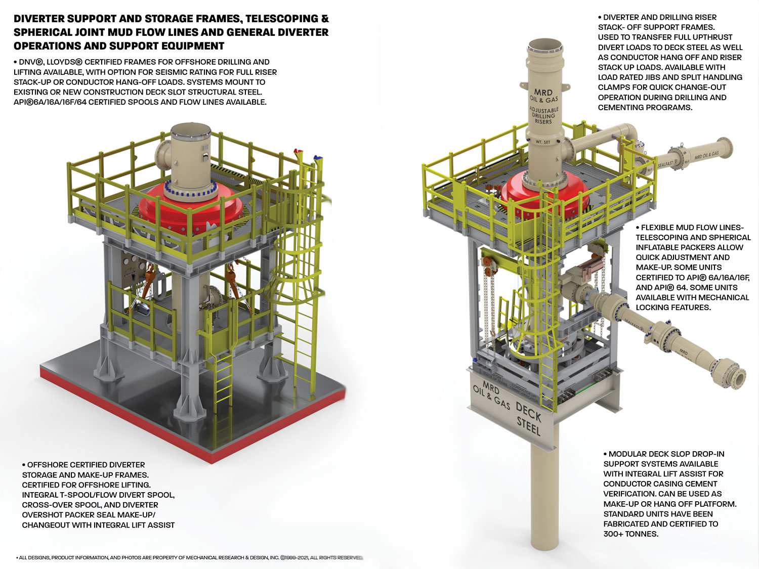
• Design pressure ratings vary from 10 PSIG for some bell nipple overshot seal housings, to 2000 PSIG for higher pressure-rated diverter overshot packers.
These housings can be mounted under the drill floor or to under-deck structural beams, can integrate a full mud pan, as well as other process and flow lines necessary for managing mud elevations and quality during returns. These units are also ideal for use as weld or bolt-on adjustable low-pressure riser seal housings and diverter overshot seal housings. They allow rapid height adjustment during diverter change-out
• Bell Nipple Overshot Seal Housings: General drilling mud collection and containment housings with integral mud pan; bleed, fill, trip, flow, and swarf lines/nozzles available upon request.
• Diverter Overshot Packer Seal Housings: quick and easy installation and actuation for high-pressure applications – can have integral flow lines to act as a t-spool for diverter stacks.
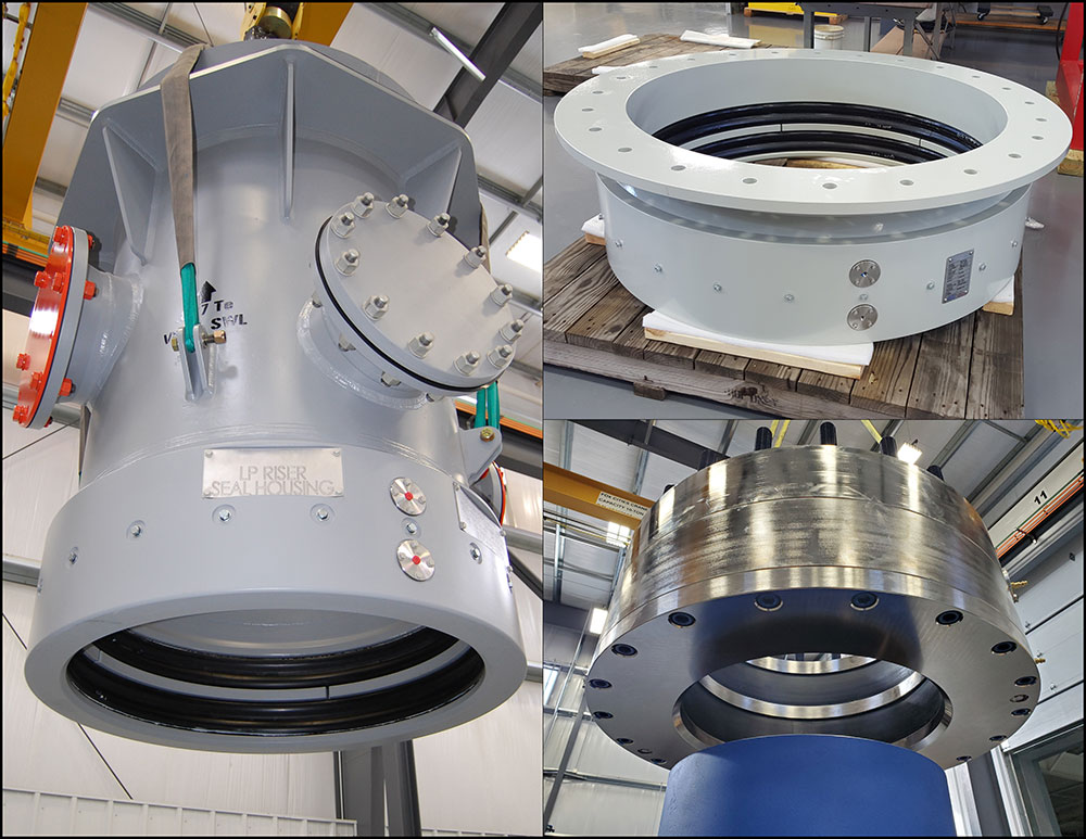
• Telescoping LP Riser Seal Housings: Best for use with telescoping low-pressure riser systems that require flexible height adjustment and large angular make-up requirements. Often referred to as telescoping riser seal housings or packer seal housings.
These dynamic seal housings are often found on floating production oil rigs, barges, and on drillships. They are commonly paired up with our inflatable spherical packers on KFDS diverter systems or as conductor unions, allowing for the drilling stack to accommodate vertical displacement from standard wave and tidal action, as well as ocean swells. These units come with low-friction mandrels and specially formulated “wear rings” for maximum life.
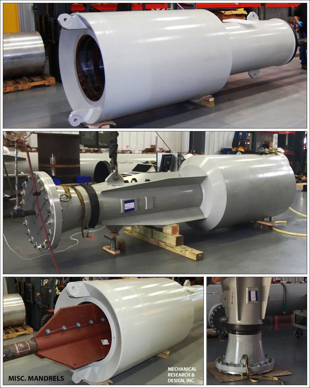
Often used as an alternative to reducing mandrel spools in bell nipple systems, our SEALFAST® Inflatable and Mechanical drop-in reducers give clients another way to manage various riser and conductor sizes needed for the multiple diverters and BOP stacks needed in some drilling programs. These units are a flexible solution to quickly reduce conductor, and riser sizes while maintaining full drill-through capability. These units can be designed for full hang-off and nozzle loads for the drill stack and can be paired with a mud box or housing that interfaces to the rig floor or underfloor structure.
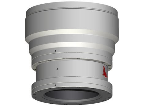
Available in a wide array of sizes and pressures, our housings can be used laterally, vertically, or on inclines. These units come with and without integral mechanical restraint for full nozzle load requirements. Our new, cutting edge, inflatable and spherical seal housing packers allow for the ultimate flexibility for your mud transport, drill through, or flow line requirements.
By utilizing our time-tested SEALFAST® inflatable and mechanical seals and packers, we are able to offer many flexible and configurable drilling stack solutions. Our products allow users to adjust for the height, angular alignment, and eccentricities in the drilling stack with unparalleled speed and efficiency. Our, fixed, telescoping, and spherical adjustment riser and mud flow line systems can be designed to accommodate down hole pressures from 5-2000 psig pressure ratings, with process mud temperatures of up to 300° F. Our active sealing technology continues to provide optimal sealing on mandrels and reducing faces, even if they corrode and wear over time, leading to lower maintenance costs
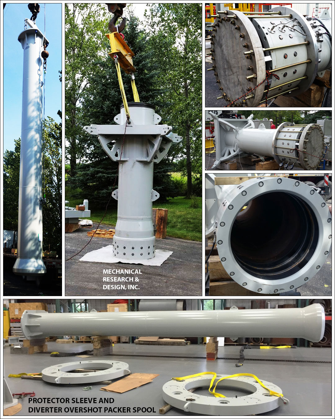
Mechanical Research & Design, Inc. designs and manufactures an assortment of fully certified Diverter and BOP support, restraint, lift, and storage equipment. Most units come certified for offshore portable equipment lifting and can include rated tie-down to deck structural steel for divert and upthrust events. Units can be adapted for integral nozzle load restraint for mud flow lines and safety rated work platforms. These frames are also used as make-up and load-rated hang-off platforms for surface drilling stacks.
A Diverter Control System can be a freestanding skid, it is designed to prevent the Diverter from shutting in the well. The EFC Group Diverter Control System does so by opening vent lines and closing mud system valves (if applicable) prior to closing the Diverter annular sealing device.
The RedSeal Dual Overshot Packer has been developed to provide a dual seal barrier in surface drilling systems used on jack-up and platform applications.
The RedSeal Dual Overshot Packer has been developed to provide a dual seal barrier in surface drilling systems used on jack-up and platform application. The system provides the operator with a primary and secondary seal system to mitigate potential environmental spills.
The system has been developed with a similar design philosophy to the RedSeal Packer system developed for drilling riser telescopic joints but does not include a facility for refill of the packer online as the seal element is a static seal and not subject to the dynamic motion associated to the RedSeal Packer system. Physically the RedSeal Dual Overshot Packer is shorter than traditional single packer systems allowing the system to be utilised in riser systems where stack-up heights are critical.
RedSeal Dual Overshot Packer can be supplied with a dedicated control system to monitor seal actuating pressure and (upon actuating pressure loss to primary seal element) switch automatically to the secondary seal, thereby minimising any environmental impact.

Petroleum and natural gas industries — Drilling and productionequipment — Shallow gas diverter equipmentIndustries du pétrole et du gaz naturel — Équipements de forage et de production — Équipement déflecteurpour gaz de surfaceOGP Draft 113354
Foreword..............................................................................................................................................................v Introduction ........................................................................................................................................................vi 1 Scope ......................................................................................................................................................1 2 Normative references ............................................................................................................................1 3 Terms and definitions ...........................................................................................................................1 4 Diverter system equipment...................................................................................................................7 4.1 General purpose ....................................................................................................................................7 4.2 Findings of blowout reports .................................................................................................................7 4.3 Applications of diverter systems .........................................................................................................8 4.4 Design considerations — Land rigs and bottom-supported marine structures .............................8 4.4.1 General....................................................................................................................................................8 4.4.2 Types of annular sealing devices in use .............................................................................................8 4.4.3 Vent outlets ..........................................................................................................................................12 4.4.4 Diverter valves .....................................................................................................................................14 4.4.5 Diverter piping .....................................................................................................................................15 4.4.6 The control system ..............................................................................................................................18 4.4.7 Kill-line facility .....................................................................................................................................18 4.4.8 Additional functions for the diverter system ....................................................................................18 4.5 Design considerations — Floating rigs .............................................................................................18 4.5.1 General..................................................................................................................................................18 4.5.2 Annular sealing devices in use ..........................................................................................................19 4.5.3 Auxiliary diverter system equipment for riser drilling .....................................................................21 4.5.4 Diverter outlets and valves .................................................................................................................23 4.5.5 Diverter piping .....................................................................................................................................23 4.5.6 Control system .....................................................................................................................................24 5 Floating rigs — Specific aspects .......................................................................................................24 5.1 Use of the marine riser ........................................................................................................................24 5.2 Additional functions of the diverter system .....................................................................................27 5.3 Comparison of types of floating support ..........................................................................................27 5.3.1 Moored drill ships ................................................................................................................................27 5.3.2 DP drill-ships ........................................................................................................................................28 5.3.3 Semi-submersibles ..............................................................................................................................28 5.3.4 Conclusion ...........................................................................................................................................28 6 Preparation for shallow gas operations ............................................................................................30 6.1 Call for tender ......................................................................................................................................30 6.2 Important issues ..................................................................................................................................30 6.3 Pre-spud checks ..................................................................................................................................31 6.3.1 Diesel engines and electrical equipment ..........................................................................................31 6.3.2 Kick and loss detection.......................................................................................................................31 6.3.3 Offshore rescue ...................................................................................................................................31 6.3.4 Offshore cooling recommendations ..................................................................................................31 6.3.5 Offshore emergency-release requirements ......................................................................................31 6.3.6 Rig safety equipment ..........................................................................................................................32 6.3.7 Safety precautions ...............................................................................................................................32 6.3.8 Diverter system ....................................................................................................................................32 6.4 Pre-spud meetings ..............................................................................................................................33 6.5 Pre-spud drills ......................................................................................................................................34 6.6 Preparing the response to a shallow-gas flow .................................................................................34 6.6.1 General..................................................................................................................................................34 6.6.2 Reminders ............................................................................................................................................35
6.6.3 Basic well-control aspects ................................................................................................................. 357 Diverter system maintenance ............................................................................................................ 38 7.1 General ................................................................................................................................................. 38 7.2 Certification and recertification ......................................................................................................... 38 7.3 Diverter system piping ........................................................................................................................ 38 7.4 Manufacturer documentation ............................................................................................................. 39 Bibliography ...................................................................................................................................................... 40
Many past shallow-gas kicks turned into uncontrolled blowouts due to the failure of former diverter systems installed several decades ago. Failure is seen as a result of the system"s complexity, its lack of functional reliability and its inability to cope with the severe dynamic loads,
1 ScopeThis International Standard specifies requirements for the selection of the diverter equipment for rigs used todrill shallow-gas-bearing formations. It covers both onshore and offshore drilling operations, and considersalso the auxiliary equipment associated with floating rigs.
3.11control functioncontrol system circuit (hydraulic, pneumatic, electrical, mechanical, or a combination thereof) used to operatethe position selection of a diverter unit, BOP, valve or regulator
3.13diverterdevice attached to the wellhead or marine riser to close the vertical access and to direct any flow into a set ofvent lines and away from the drilling unit
3.18diverter systemassemblage, comprising an annular sealing device, flow control means, vent system components and controlsystem, which facilitates closure of the upward flow path of the well fluid and opening of the vent to theatmosphere
3.54subsea diverterseabed diverterset-up of equipment attached to the bottom of the marine riser and connected to the 762 mm (30 in) subseawellhead housing, designed to close the well in case of shallow-gas influx and to direct it through two subsealateral vent outlets
3.58telescopic joint packertorus-shaped, hydraulically, pneumatically or mechanically actuated, resilient element between the inner andouter barrels of the telescopic joint which serves to retain drilling fluid inside the marine riser
The diverter system is designed to permit the drilling crew to blow down shallow-gas accumulations downwindof the rig. Until a sufficient casing length has been set to allow a well to be shut-in during a kick, the divertersystem is the only line of defence, and is only expected to contain the hazard temporarily, although as long aspossible.
The diverter system is not intended to be a well-control device. It simply allows the flow to be diverted in asafe manner in order to allow enough time to attempt regaining primary control of the well and, should thelatter fail, enough time for proper evacuation of the drilling crew or for proper move-off of the drilling unit fromthe location (floating rigs), until the flow stops due to gas accumulation blow-down, hole bridging, holecollapse, etc.
Blowout inquiries have concluded that the original designs underestimated the fact that shallow-gas blowoutsproduce huge amounts of gas, together with abrasive solids, flowing at very high speed, producing severedynamic loads, and eroding and destroying many parts of the existing diverter systems.
Statistics obtained in the 1990s in Norway have shown that 54 % of shallow-gas blowouts caused severedamage or total loss of the drilling structure and support, due to the failure of the diverter system.Unfortunately, many lives were lost during those dramatic events.
It is therefore of paramount importance to select suitable equipment able to function in a reliable and safemanner, i.e. able to operate whenever required under the worst possible conditions. Diverter equipment shallalso be able to cope with the prevailing dynamic loads and associated effects.
In the insert-type diverter assembly, the insert packing is latched in place into a diverter assembly, which inturn is locked inside the support housing. This housing provides two outlets, one for the mud returns to flowtowards the shakers, one for the diverted fluids to flow out through the vent line(s). The insert is removed priorto pulling or running the bottom-hole assembly (see Figure 1).
This set-up requires a conventional bag-type preventer and a drilling spool (or diverter spool) which aredirectly located on top of the first casing (conductor pipe, drive pipe). This set-up is therefore below the rotarytable and below the flow-line, unlike the insert-type diverter assembly (see Figure 2).
Key1 Bell nipple 6 Vent line2 Flow line 7 Diverter spool3 Fill-up line 8 Hydraulically operated full opening valve4 Annular packing element 9 Drive / Conductor pipe5 Standard bag-type preventer
insert-type packer usually closes fast (a few seconds), while the operation of the vent and flow- line valves takes much longer (> 40 s), hence imposing a sequencing system to prevent closure of the packer prior to proper operation of the valves;
The standard hook-up option eliminates the need for a flow-line valve, as the flow-line is located at the level ofthe bell nipple, well above the diverter set-up.
The use of an overshot packer, required for length adjustment below the diverter system, is also eliminated,hence removing a potential leak point at pack-off level. Conversely, this adjustment joint and its packer can beused without risk above the bag preventer, as it will not experience any gas flow pressure.
Another safe alternative is to use an integral diverter assembly, which integrates the diverter spool and theannular packing into a single piece of equipment.
In this system the motion of the annular piston is used, in one stroke, to first open the vent lines and then stopthe upward flow. The flow-line is located at the level of the bell-nipple, well above the integral diverterassembly, hence eliminating the need for a specific flow-line valve (see Figures 3 and 4).
Several types of valve are commonly associated with diverter systems: gate valves, ball valves, switchablethree-way target valves, knife valves, valves integral to the diverter unit and sometimes burst disks.
For insert-type diverter systems requiring actuation of valves on both shaker and vent lines, an interlocksystem shall prevent the diverter from closing before the valves are in the correct position (i.e. shaker valveclosed, vent-line valve open). This is of paramount importance with these systems, where the response timeof the insert packer is much lower than that of the shaker and vent-line valves [usually less than 10 s to closeon a 127 mm (5 in) drill pipe].
Actuators fitted to a diverter valve shall be sized to open the valve at least with the rated working pressure(WP) of the diverter system applied across the valve.
The safest and most reliable option is the integral diverter system (see Figures 3 and 4) in which the physicalneed for valves is eliminated. In such a system, the shaker and fill-up lines are located far above the divertersystem within the rig sub-structures, and do not require any shut-off valves.
Diverter piping shall consequently be sized and its layout designed such that the anticipated back-pressure,calculated with realistic gas flow rates, do not exceed the rated working pressure of the diverter system, donot exceed the design pressure of other equipment, and do not place undue pressure on the wellbore.
At the rig site location, the diverter vent-lines shall extend a sufficient distance in the most appropriatedirection from the rig to permit safe venting of diverted well fluids.
Consequently, the minimum required nominal internal diameter (ID) of diverter outlets and vent-lines shall be355,6 mm (14 in). The piping wall thickness shall not be less than 19,05 mm (0,75 in).
The diverter control system shall be designed and sized in accordance with API 16D:2005, Section 5.5. It shallcontain the minimum of functions. Preferably, a one-button or lever-activated function shall operate the entirediverter system.
A 38,1 mm (1½ in) hydraulic operating line should be used for diverter systems with a 1½ in NPT closingchamber port size. The hydraulic line for the opening chamber port may be 25,4 mm (1 in).
Many shallow-gas blowout reports have mentioned failures of the pneumatic control system used to operatediverter valves (e.g. failure to work as required when valves stems are blocked with solids). A pneumaticcontrol system shall therefore be avoided on rigs, if possible.
Each diverter system should incorporate a kill-line facility (including a check valve) to allow pressure-testing ofthe annular packing element closed on open hole, with no pipe in hole. This facility can also be used toperiodically flush the system clean.
Another advantage of a kill-line facility is to pump water through the diverter system during a gas-flow divertingoperation, in order to wet the gas and accordingly reduce the fire risk.
The use of a diverter system (alone or combined with a BOP set-up) should be considered on multi-wellplatforms, due to potential hazards such as collision with adjacent wells or surface-gas accumulations due topoorly cemented casings.
Though many parts of the diverter system are identical to those used on land rigs and bottom-supportedmarine structures, others are specific to floating units and are reviewed hereafter.
When drilling shallow-gas-bearing formations with a riser, two types of sealing device are used: the surfaceinsert-type diverter assembly and the subsea diverter.
By design, this system is basically similar to the system used on land rigs and bottom-supported marinestructures. The diverter support housing is permanently fixed to the drill-floor substructure below the rotarytable at the upper end of the marine riser system, and provides outlets for the shakers and for ventingpurposes. The diverter assembly is locked down inside the housing, and the insert packer is locked inside thelatter.
For floating supports, the possibilities to improve the surface vent-lines network and routing being substantiallyreduced, the subsea diverter system is a safer alternative. The basic set-up includes, from top to bottom: aflex joint, an annular BOP (or a shear ram unit), a diverter spool and a riser hydraulic connector (seeFigure 6).
If the subsea diverter option is selected, it is recommended to hook up a riser booster line above the upperclosing unit (bag or shear ram), to eliminate any gas which has entered the riser before complete well shut-off.An additional diverter system (e.g. the basic insert-type assembly) is required at surface to deal with this gasinflux (see also 4.5.2.3 and 5.2).
Prior to choosing this option, it is important to look carefully at the water depth and the type of support vesselwhich has been selected. Even after its transit through the water column, gas still represents a potentialexplosion and fire hazard, mainly as it concentrates in the moon-pool area. With gas being vented at seabedlevel and percolating up to surface, the subsea diverter is probably not the best choice with a drill-ship inshallow water depths.
Key Key1 539,7 mm (21 1/4’’) Flex Joint 1 539,7 mm (21 1/4’’) Flex Joint2 539,7 mm (21 1/4’’) Annular BOP 2 539,7 mm (21 1/4’’) Annular BOP3 539,7 mm (21 1/4’’) Diverter spool w/ integral valving 3 539,7 mm (21 1/4’’) Shear ram and 304,8 mm (12’’) outlets 4 539,7 mm (21 1/4’’) Diverter spool4 Guide structure 5 Outlet nozzle5 762mm (30’’) Hydraulic connector 6 762 mm (30’’) Hydraulic connector
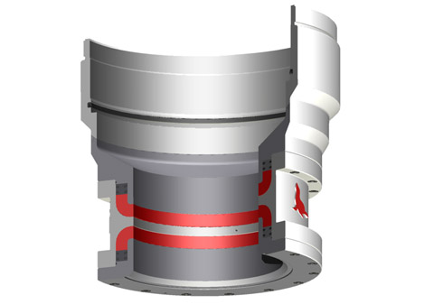
NOTE The diverter is shown here in the drilling mode. When the diverter closes in case of gas influx, the piston movesupward, opening the flow path to the vent line while closing the flow path to the flow line.
Should surface diverting be considered as too hazardous (in particular if the integral diverter system is notavailable), the requirement for safe operation is to use the subsea diverter. Its use depends however on thewater depth at the drilling location, the virulence of reported local shallow-gas events, the type of supportvessel contemplated and the competence of the chartered drilling contractor.
The insert-type diverter system should only be used in conjunction with a subsea diverter or with a BOP stack,to circulate and vent out any gas trapped in the riser (see 5.2).
The same comments for land rigs and bottom-supported marine structures given in 4.4.3 and 4.4.4 apply tovent outlets and diverter valves for floating rigs.
On floating rigs (as for land rigs and bottom-supported marine structures), since the size and number of vent-lines have a great influence on surface and downhole hazards, two properly sized vent-lines shall be used.The minimum nominal ID of diverter outlets and vent-lines shall be 355,6 mm (14 in).
Key1 Flow selector always open2 Diverter with integral valve functions3 To Shale shaker4 To Vent lines5 To Starboard vent line6 To Port vent line
The diverter control system shall be designed and sized according to API 16D:2005, Section 5.5. Pneumaticcontrol systems shall be avoided on rigs working in shallow-gas-prone areas.
Each operating company has its own drilling policy with respect to using (or not) the marine riser while drillingshallow-gas-prone formations. The general mistrust of existing diverter systems on most floating rigs has ledsome operators to adopt a riserless approach. The following comments can be made.
Whatever the pros and cons of riser use, a preliminary careful and thorough review of the reliability andcapacity of the rig diverter system (see 4.5.2) and of the reliability and capacity of the emergency-releasesystem of the floating-support mooring lines can provide decisive criteria to assist in selecting the beststrategy.
Gas can inadvertently enter the riser when the BOP is shut-in on a kick. Gas can also enter the riser if the rams leak after the BOP is closed. Using the diverter system, the gas in the riser can be safely removed and diverted overboard,
After a kick circulation is completed, some compressed trapped gas can remain between the closed BOP and the choke-line connection. This gas will tend to migrate into the riser when the BOP is re-opened. Using the diverter system, this gas can also be safely removed and diverted overboard.
a competent drilling crew, having past experience in shallow-gas drilling, purposely trained and familiar with the diverter equipment and its proper testing, maintenance, and operation;
Prior to drilling a shallow-gas formation, all the diverter system components shall be inspected and tested toascertain proper installation and function. As a minimum, the following tasks shall be carried out.
Ensure that any fill-up line which can be exposed to the gas flow is protected with a check valve; this line and check valve shall have a WP equivalent to that of the diverter system.
d) Simulate loss of rig air supply to the diverter control system and determine effects, if any, on the diverter system, valves, and back-up systems.
On a routine basis, when in primary diverter service (no BOP installed), function tests should be performeddaily using the driller’s panel to verify that functions are operable. Fluid should be regularly pumped througheach diverter line during drilling operations to ensure that they are clear of obstructions at all times.
review all preliminary checks related to, among others, the diverter system, kick detection equipment, kill mud volumes, emergency power supply, safety, rescue and emergency equipment, emergency communication systems, mooring equipment if applicable, etc.;
All concerned personnel should therefore be familiar with the diverter system components and installation,and should be capable of reacting quickly and efficiently to potential situations requiring use of the diverter.
Any defect or problem with equipment or personnel identified during any of these pre-spud drills should beimmediately reported and dealt with before drilling is permitted to start. Thereafter, drills should be conductedat appropriate intervals to ensure personnel are capable of quickly and competently reacting to situationsrequiring use of the diverter.
If practically feasible, a tentative well kill should be attempted immediately with heavy kill mud and themaximum pumping rate available, after the diverter system has been activated, to try to stop the gas flowdownhole, prior to complete well unloading.
A schedule for routine inspection and maintenance of diverter systems equipment should be prepared andmaintained by the rig operating personnel. Specific guidelines for each diverter component or sub-systemshould be based on installation, operation and maintenance manuals provided by the equipmentmanufacturer.
During diverter function tests, observe all components of the diverter system including the diverter, valves, valve actuators, piping, and control panel to verify that there are no leaks in the system. If a leak is discovered, it should be repaired immediately.
All diverter equipment shall be maintained with original equipment manufacturer’s (OEM) genuine or approved spares and shall be operated and tested in accordance with that manufacturer"s recommended procedures. Major repairs, overhaul on and recertification of diverter equipment shall be performed either by the OEM or an alternative provider, but then only when approved by the OEM.
A visual inspection, a body-pressure test and a full-function test shall be carried out once a year on a diverter test stump at surface, in accordance with the manufacturer"s specification for such a test and witnessed by a certified third party. Results of the inspections and tests, including follow-up, shall be documented, providing full traceability and be part of the formal service history.
At least every five years, the diverter system components shall be inspected for repair or remanufacturing by the OEM or OEM-approved service provider. Upon completion of the inspection, the OEM shall provide a Certificate of Conformance (COC).
The wall thickness on all undesirable turns and bends (if any) in the diverter system piping should be checkedat least annually and after each use of the system to divert a well kick. Erosion of metal from the turns andbends can be severe if sustained flows of gas-associated solids are diverted through the system.
Installation, operation and maintenance manuals furnished by the manufacturers of the various components ofthe diverter system should be readily available for training, reference, and use by maintenance personnel.

D eep well programs on the Arabian peninsula present unique challenges during the initial phase of drilling operations.Shallow gas pockets may be encountered that require managedwell bore control that is not currently available on existing land rigs.Utilizing feedback from the Saudi Arabian Oil Company (SaudiAramco), Dril-Quip, Inc. has developed the Arabian DiverterSystem (ADS) to address these challenges.The ADS (patent pending) is a portable diverter installed on theconductor and establishes a pressure-tight seal to enable controlleddiversion of any gas pockets that might be encountered. This divert-er system integrates three elements – the diverter housing, packingelements and an overshot spool-type connector – into a unitizedprotection device. The ADS incorporates safe, reliable field-proventechnology and performance features into a 500-psi-rated workingpressure design.Elastomer packers in the diverter close and seal around pipesuspended through the rig’s rotary table, isolating the rig floor fromfluids and gases flowing from the well bore. Large outlets locatedbelow the packers control and divert the flow to a designated area.Hydraulic controls for the diverter system are incorporated into therig’s BOP control system. Valves with hydraulic actuators aremounted on each of the diverter outlet lines to control the move-ment of fluids and gases through the system.The handling and test tools provided facilitate testing, operationand maintenance of the system.
FEATURES• Large-bore diverter accommodates 36" drift• A range of split insert packers provides well bore protection during both drilling and casing operations• Split packer design also facilitates running selected packer elements through a 37-1/2" rotary table• Split insert packer design simplifies installation via weight-set, lock-ring style auto-locking components; no hydraulics required• Overshot radial bolt connector features quick, easy make-up using standard impact wrenches• Overshot connector packer seal is hydraulically energized for reliable control of the well bore fluids• Engineered, designed and operated in accordance with applicable API industry standards• Adaptable to most land drilling rigs• Complete ADS diverter and valve system available from single source (Dril-Quip)
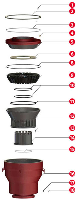
Packer Lockdown Ring Packer Load Ring Main Packer Assembly Main Packer Operation Port Main Body
10" Split Packer 18" Split Packer 27-1/2" Split Insert Packer 32-1/2" Solid Insert Packer Diverter Housing Retrieving Rod Assembly Handling Tool 10" Release Ring 18" Release Ring 27-1/2" Release Ring Tool Joint Pin Diverter Test Tool Diverter system valves not shown in illustration.
Main PackerThe Main Packer is housed in the main body of the diverter, andconsists of a tubular elastomer seal with metal rings molded oneach end. The one-piece packer is retained in the main body ofthe diverter by the packer lockdown, retaining and load ring.The Main Packer functions the insert packers when the diverteris closed. Hydraulic pressure deflects the packer toward the bore,which in turn deflects each of the insert packers installed. TheMain Packer is only removed during maintenance operations. 10" Split Insert PackerSolid Packers and Split Insert PackersThe Solid and Split Insert Packers land in the main body ofthe diverter and are designed to close and seal around variouspipe sizes. The packers consist of a tubular elastomer seal withmetal rings molded on each end. The Split Insert Packers aresplit in half so that they can be installed or retrieved whilepipe is suspended through the rotary table. A spring-loadedlockdown ring is bolted to the top of the packer and retains it inthe previously installed larger packer. Tapped holes in the topof the lockdown ring permit the swivel insert retrieving rodsto release the lockdown ring and recover the packer assemblywhen necessary. Each Split Insert Packer has two alignment slotslocated at the top of the packer to orient the packer assemblysuch that the split between the two halves is offset 90° from the 18" Split Insert Packersplit between the two halves of the previous size. All packers arerated to 500 psi.10" Split Insert PackerThe 10" Split Insert Packer incorporates J-slots on the ID tointerface with the Packer Handling Tool. The packer is operatedwith 925 psi and has a minimum closing diameter of 4-1/2".18" Split Insert PackerThe 18" Split Insert Packer lands in the 27-1/2" Solid Packerand is normally run with the 10" Split Insert Packer. The packeris operated with 850 psi and has a minimum closing diameter 27-1/2" Split Insert Packerof 9-5/8".27-1/2" Split PackerThe 27-1/2" Split Insert Packer lands in the main body of thediverter. It is operated with 750 psi and has a minimum closingdiameter of 26".32-1/2" Solid Insert PackerThe 32-1/2" Solid Insert Packer lands in the main body of thediverter housing. It is operated with 750 psi and has a minimumclosing diameter of 28". 32-1/2" Solid Insert Packer
4Operations Easy, simple Diverter Housing installation Test the Overshot and Diverter Packers The integral Overshot Packer is an adapter The integral Overshot Packer and Split spool that stabs over and provides a Insert Packers are tested with the Packer molded elastomer seal around the field-cut Handling and Diverter Test Tool. 36" conductor casing. A field-welded ring on the conductor OD provides a shoulder for the overshot spool radial bolt-type connector to contain any end-load forces in the event of a shallow gas encounter.
Step 1 Step 2 • Install conductor casing • Test system components with Packer • Weld ring on upper section of casing Handling and Test Tool • Install ADS Diverter System • Retrieve Test Tool • Make up Radial Bolt Overshot Connector • Energize Overshot Packer element
5Reliable managed bore protection Reliable managed annulus duringduring drilling operations casing installationThe Split Insert Packers can be installed The Split Insert Packers are retrievedassembled together with the Packer and the 32-1/2" Solid Packer isHandling Tool or individually with the installed to provide protection duringRunning and Retrieving Rod Assembly. surface casing installation.Hydraulic pressure applied to the MainPacker element functions the InsertPackers closed as required during drill-ing operations.
Step 3 Step 4 • Run drill bit • Run surface casing and cement • Reinstall Packer assembly • Nipple down ADS Diverter System • Drill out for surface casing • Nipple up BOP stack • Retrieve bit and bottom hole assembly
3 THE. IN-* OFFS^ WJS. ADER FOR RELIABLE RILLING EQUIPMENT Introduction Vetco Gray has been a leader in supplying drilling equipment to the oil and gas industry since 1906, when Regan Forge began manufacturing crown blocks and traveling blocks for the California exploration market. Today, we are the world"s leading supplier of marine drilling riser systems with more than 65% of the global market. Our legacy of technology development and innovative solutions puts us in the forefront of offshore drilling, especially for deepwater exploration. Vetco Gray supplied the complete drilling riser system for the world"s first, and to date, only, exploration well in water depths greater than 10,000. We provide a complete line of Capital Drilling Equipment for fixed platform, jackup and floating rig applications. Table of Contents Diverters for Jackup & Platform Drilling Units KFDJ 3 KFDJ Model J 4 Diverters for Floating Drilling Units KFDS 5 CSO: Complete Shut-Off 5 Drilling Riser System Components Telescopic Joints 6 Tensioner Support Rings KT 7 SDL and SDL with Fluid Bearing.. 8 Marine Riser Couplings MR-6HSE 9-10 MR-6H SE Riser Adaper 10 MR-6E 11 HMF Class E, F, G, H, J 12 Subsea Connectors H-4 Connectors: Wellhead & LMRP ExFH-4 15 EH-4 15 ExFHAR 15 DWHDH-4 15 SHDH-4 16 VX-2, VGX-2 and VT-2 Gaskets Composite Material Risers 19 Aftermarket Support Riser Inspection (RADAR) 20 Facilities Locations Ancillary Riser Equipment Spiders 13 Intermediate Flex Joint 14 Single Flex Joint 14
4 \ Diverters for Jackup & Platform Drilling Units KFDJ Diverter Systems KFDJ Diverter Complete protection while running casing strings and drilling hole is provided by a full range of insert packer sizes, all of which use a "J" type running tool. Available with a rotating insert which provides low pressure packoff on the kelly or drill pipe during drilling. Features The fixed support housing, a proprietary feature, is securely bolted to the rotary beams and provides fixed outlets for flowline, fill-up line and vent lines. The support housing allows installation of outlets up to 20" diameter to virtually any configuration. Diverter, spacer spool and overshot packer assembly may be pulled or run without connecting or disconnecting the flowline, fill-up line and vent lines. Mudline suspension hangers and bit sizes up to 27.41" for 37-1/2" rotaries or 36.41" for 49-1/2" rotaries can be run without removing the diverter assembly. Diverter, spacer spool and overshot packer each fit through a 37-1/2" rotary table. Minimum bore through the standard support housing is 36-1/2" ID for the 37-1/2" in rotary installation. Optional 37-1/2" bore is available. The overshot packer on the bottom of the diverter spacer spool assembly reduces the nipple-up time normally required to weld flanges or hubs to casing. Dimensional Data - Standard Hookup KFDJ with 12" Nominal Outlets* Rotary Table А в С D E F All dimensions in inches. * Number and size of outlets are optional. <25Vetcogray
5 Diverters for Jackup & Platform Drilling Units KFDJ Model "J" Diverter Systems KFDJ Model "J" Designed with all the field proven features of the standard KFDJ diverter, but with fewer hydraulic connections, Vetco Gray"s KFDJ Model "J" diverter system has a "J" lock between the diverter and the support housing. The Model "J" requires only 3 hydraulic functions: energizing/venting the diverter packer, the flowline seals and the overshot packer. The "J" slots in the support housing align the diverter outlets with the housing outlets. A mechanical latch secures the diverter in the housing and the handle position provides a clear visual indication of lock engagement. Features Simplified design All components of the support housing and the diverter assembly area heavy wall construction for pressure containment and erosion protection during high velocity, multi-phase flow Full size range of insert packers Custom designed for specific applications KFDJ Model "J" Diverter KFDJ "J" Diverter (Handling Tool) Dimensional Data -Standard Hookup KDFJ "J" with 12" Nominal Outlets* Standard handling tool has a 4-1/2" IF API tool joint box up and pin down, but can accommodate other tool joints as desired. The optional test tool provides the means to pressure test the entire diverter system. Rotary Table A В С D All dimensions in inches. * Number and size of outlets are optional. E
6 Diverters for Floating Drilling Units KFDS Diverter Vetco Gray is the market leader for diverter systems in the offshore drilling market. For 25 years, Vetco Gray has provided KFDS Diverter technology with field-proven protection from shallow gas blowouts. Compact: the Diverter Support Housing, overboard lines and associated valving are permanently installed on to the Rig structure. The Diverter Assembly is run and retrieved through the rotary table with the marine riser. Rf 1 Г Flexible: Variable outlet sizes and orientations can accommodate most any rig design. Valving is external, allowing for rig design variation and valve/actuator preferences. Vetco Gray is a single-source supplier for a complete system, including diverter assembly, controls and valves. An integrated package, engineered to specific requirements, will provide maximum safety, efficiency and savings. Diverter Insert Diverter Housing CSO Diverter Flow Lino Running ^^k pressum " Energized Proflle FlowLine Seals Diverter Assembly pherical Element Diverter Housing Standard housing has multiple outlets, up to 20" diameter. Features Housing accommodates large diameter riser buoyancy modules Complete open-hole shutoff with 20" through-bore second closure time on pipe or open hole 500 psi rated system Control system maximum operating pressure of 1,500 psi High capacity systems available for supporting the Riser String from Diverter Housing in emergency hangoff situations Connection block enables hydraulic operating functions to be quickly attached or disconnected Standard housing holds multiple outlets, up to 20" diameter Outl.tNom.(»n.) Spherical Element Minimum Dimensions (S^vetcogray Standard housing has multiple outlets, up to 20" diameter Flex Joint Crossover Flange Running Tool Profile
7 Drilling Riser System Components Telescopic Joint Vetco Gray telescopic joints compensate for heave and offset of the vessel and are available for all riser systems. Available for MR-6E, MR-6H SE, and HMF riser systems ^ИСГ Maximum rated riser tensile load capacity in locked position ^ & Hydraulic latch release for inner and outer barrels available Dual split/solid packer elements Fixed or rotating integral tensioner rings Prepped for non-integral SDL, SDC and KT tensioning rings Fluid or roller bearing prep (S^vetcogray
9 Drilling Riser System Components SDL/SLS Tensioner Support Ring Features & Benefits Riser tensioner lines remain attached to the SDL/SLS Ring so riser tensioning lines remain properly spaced out at all times Hydraulically disconnects from the Telescopic Joint and locks to a mating profile on the bottom of the Diverter Support Housing for convenient out-of-the-way storage The SDL/SLS Ring is full opening to the Diverter Support Housing The SDL/SLS Ring may be used with a Telescopic Joint Fluid Bearing, allowing the drilling vessel and tensioners to rotate relative to the riser string Telescopic Joint is run and pulled through the rotary table without disconnecting the tensioning lines from riser tension ring Hydraulic piping for lockdown/storage dogs remains permanently connected Diverter Stow Dogs {shown out or phase) SDL Tensioner Support Ring Tensioner Ring Pad Eyes Hydraulically Actuated Riser Support Dogs SDL Tensioner Support Ring with Optional Fluid or Roller Bearing Fluid Bearing Assembly Fluid Monitor Line Fluid Fill / Return Line Features & Benefits Incorporates field-proven SDL/SLS Ring technology Low breakout torque values with high tension loads Fluid bearing has a carbon/teflon backup bearing Pressures in the fluid bearing can be observed and controlled via a hydraulic monitoring and replenishment circuit Stop Ring to prevent overpressuring Telescopic Joint Outer Barrel (S^vetcogray


 8613371530291