
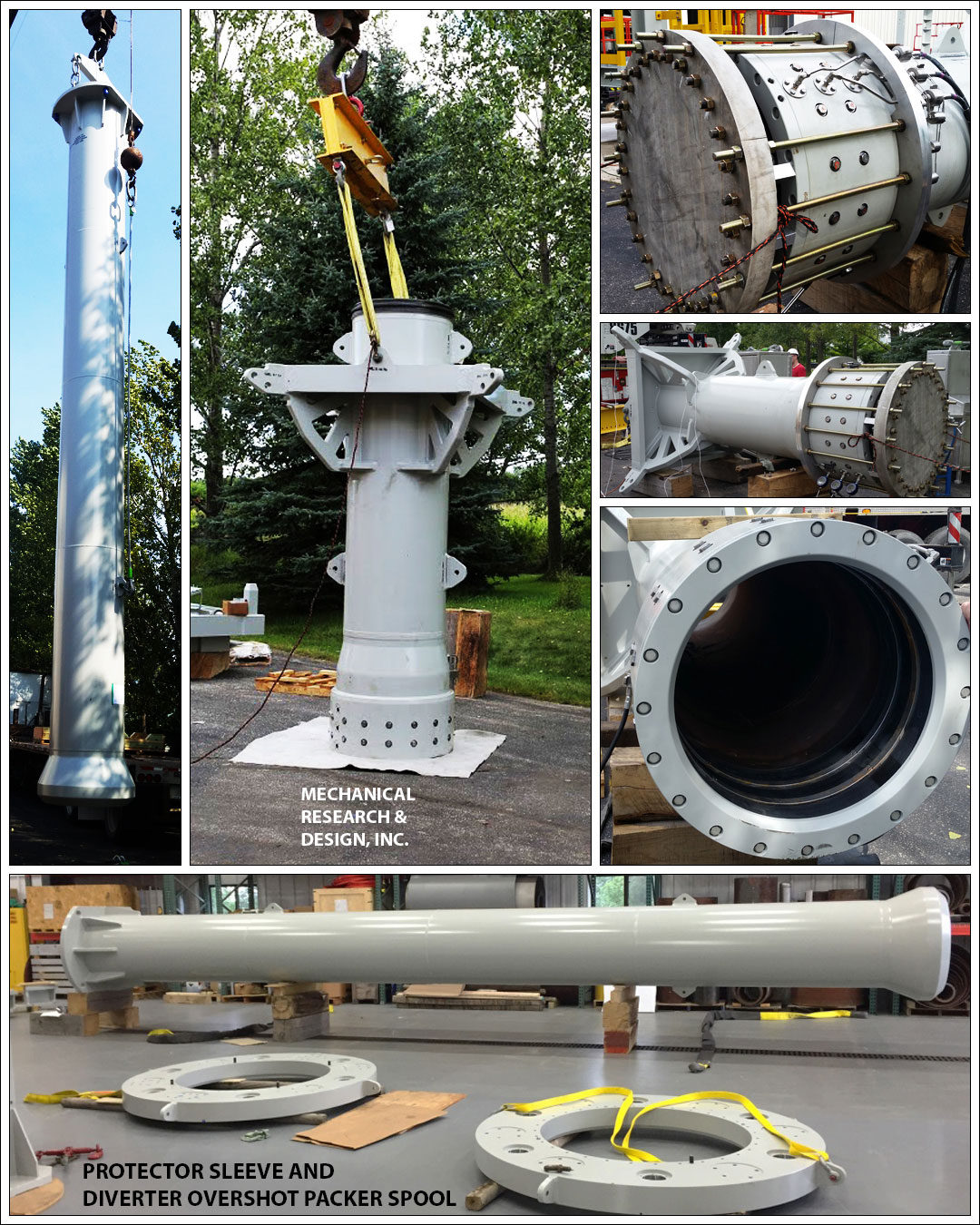
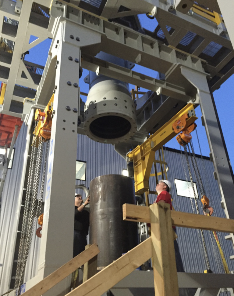
diverter overshot packer quotation
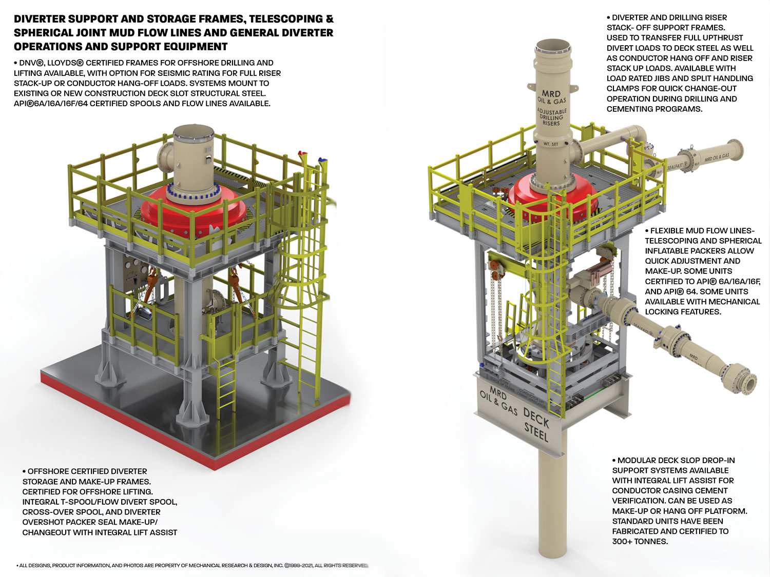
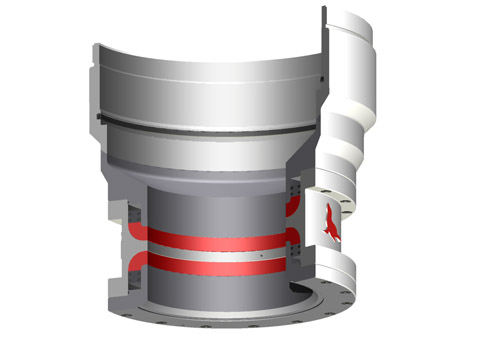
The diverter assembly is the uppermost component of the riser system.It is not used to shur or seal the well completely, but to either direct the teturing drill fluit or control the blowout and surface layer gas, when encountering the gas, the diverter can close off around drillpipe or casing,and open the special direction vent line on board at the same time
Diverters are used with casing advancement systems when drilling through overburden. The diverters slip over the top of the casing to direct cutting, and fluids away from the hole. A hose can be connected to the diverter outlet to further direct the flow away from the hole. Please contact your Hole Products representative for additional product details.
• Design pressure ratings vary from 10 PSIG for some bell nipple overshot seal housings, to 2000 PSIG for higher pressure-rated diverter overshot packers.
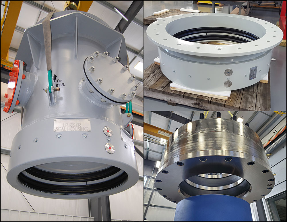
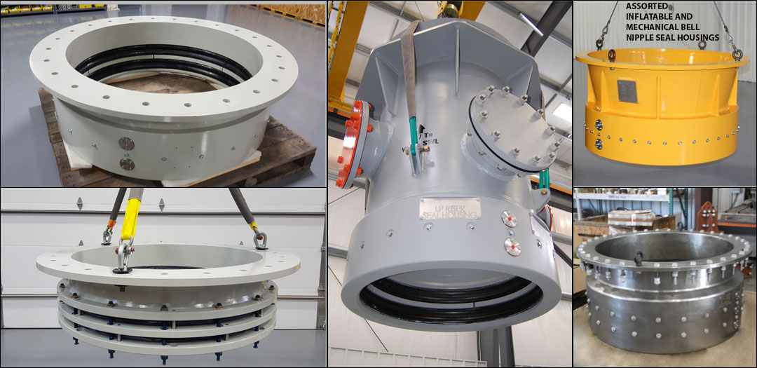
These housings can be mounted under the drill floor or to under-deck structural beams, can integrate a full mud pan, as well as other process and flow lines necessary for managing mud elevations and quality during returns. These units are also ideal for use as weld or bolt-on adjustable low-pressure riser seal housings and diverter overshot seal housings. They allow rapid height adjustment during diverter change-out
• Bell Nipple Overshot Seal Housings: General drilling mud collection and containment housings with integral mud pan; bleed, fill, trip, flow, and swarf lines/nozzles available upon request.
• Diverter Overshot Packer Seal Housings: quick and easy installation and actuation for high-pressure applications – can have integral flow lines to act as a t-spool for diverter stacks.
• Telescoping LP Riser Seal Housings: Best for use with telescoping low-pressure riser systems that require flexible height adjustment and large angular make-up requirements. Often referred to as telescoping riser seal housings or packer seal housings.
These dynamic seal housings are often found on floating production oil rigs, barges, and on drillships. They are commonly paired up with our inflatable spherical packers on KFDS diverter systems or as conductor unions, allowing for the drilling stack to accommodate vertical displacement from standard wave and tidal action, as well as ocean swells. These units come with low-friction mandrels and specially formulated “wear rings” for maximum life.
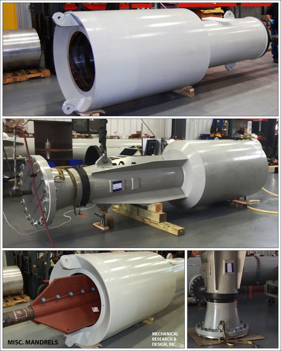
Often used as an alternative to reducing mandrel spools in bell nipple systems, our SEALFAST® Inflatable and Mechanical drop-in reducers give clients another way to manage various riser and conductor sizes needed for the multiple diverters and BOP stacks needed in some drilling programs. These units are a flexible solution to quickly reduce conductor, and riser sizes while maintaining full drill-through capability. These units can be designed for full hang-off and nozzle loads for the drill stack and can be paired with a mud box or housing that interfaces to the rig floor or underfloor structure.
Available in a wide array of sizes and pressures, our housings can be used laterally, vertically, or on inclines. These units come with and without integral mechanical restraint for full nozzle load requirements. Our new, cutting edge, inflatable and spherical seal housing packers allow for the ultimate flexibility for your mud transport, drill through, or flow line requirements.
Cameron diverters are fully customizable for your floater and jackup rig operations, respectively. Designed for reliable, efficient use, each system consists of a housing, outlet valves, running tools, controls system, diverter assembly, overshot packers, and storage skids.
The CF-A diverter supports up to 75.5-in rotary tables and has a hang-off capacity of up to 2,500,000 lbm. It uses a single annular packing element with a pressure rating up to 500 psi. The CF-A diverter features four hydraulic locking dogs that reduce hosing and simplify operation. It eliminates the need to secure hoses to the diverter assembly while providing hydraulic fluid for the operations.
The CF-B diverter supports up to 47-in rotary tables and is qualified up to 2,000 psi. Packers can be split and hinged to allow them to be changed out with pipe in the hole. J-slot type running tools are entirely mechanical and require no hydraulics.
A Diverter Control System can be a freestanding skid, it is designed to prevent the Diverter from shutting in the well. The EFC Group Diverter Control System does so by opening vent lines and closing mud system valves (if applicable) prior to closing the Diverter annular sealing device.
This invention relates in general to diverters and blowout preventer systems for drilling rigs. In particular, the invention relates to diverter and blowout preventer systems and methods for use with bottom supported offshore drilling rigs.
Diverter systems for bottom supported offshore drilling rigs are known in which a diverter element is provided in the support housing attached to the support beams beneath the drilling rig rotary table. Such diverter systems have provided for a vent line and a flow line in the permanent housing beneath the rotary table. Such systems have required external valve systems in the vent line to assure that when the diverter in the permanent housing opens the fluid system to the vent line, the flow may be directed away from the drilling rig. In such prior art systems, a spacer spool has been provided beneath the support housing and a thirty (30) inch overshot connection has been provided between the spacer spool and the thirty (30) inch outside diameter drive pipe or structural casing.
Fatal and costly accidents have resulted from the complexity of prior art diverter systems described above. Typical prior art diverter systems have included an annulus closing device, external vent and flow line valves, actuators, limit switches and sequenced controls. This complicated valving and piping of the prior art has been further complicated by the inherent risks of manipulating loose packer inserts into the diverter itself. The complexity of the prior art systems has invited a variety of human error and equipment malfunctions.
One problem with the prior art systems has involved the use of external valving in the diverter system. Valves which are external to the diverter unit not only add clutter to the diverter system and the rig configuration, it has also required multiple control functions which are required to operate perfectly. For example, the prior art diverter system valves have required an actuating pressure signal that is regulated to a discrete pressure level different from the operating pressure level of the diverter unit. The need for separate and different control functions executed in only one safe sequence has required separate pressure regulators and connecting components that are in different locations on the underside of the rig floor. Such a requirement has invited mistakes and malfunctions.
In addition to the problem of multiple control functions, there has existed problems with crossed connections in prior art diverter systems. Misconnection of control lines can cause a valve to be closed when it should be open which could result in an explosion in the diverter or breach of the casing.
Another problem of the prior art diverter systems has been exposure to the marine environment of delicate parts such as hydraulic tubing and fittings, limit switches, mechanical linkages and valve actuators. Such exposure has in the past caused breakage and damage to such parts. System malfunctions which result from damage to exposure can be catastrophic.
Another problem of prior art diverter systems has been the result of vent line blockage. Because the vent valve has been remote from the diverter unit itself, a stagnate space has existed at a critical location in the vent line. Buildup of solids and caking of mud in such a dead space may cause the critically important vent line to be choked off. A restricted or shut-off vent line may cause a dangerous pressure increase while being called upon to divert.
Still another problem of prior art diverter systems has involved the use of component sources from a number of different manufactures. The annulus closing device, vent and flow line valves, actuators, sequencing devices and control system components have typically been provided by a different manufacturer. Rig operating personnel are usually burdened with devising the vent line valve circuit interconnecting the components (which are often widely physically separated when installed) and stocking a varied assortment of spare parts using extraordinary caution to avoid misconnections and keeping a number of rig personnel trained to operate and maintain a diverse assortment of complicated components.
Still another problem of prior art diverter systems for bottom supported rigs has been the requirement of a high pressure valve in the vent line. Closure of such a valve has enabled the diverter unit to be converted to a blowout preventer after sufficient casing pressure integrity has been established. However, if this valve should inadvertently be closed during an attempt to divert, breach of the casing or explosion of the diverter system could threaten the safety of the rig itself.
Still another problem of prior art diverter systems has been the result of valve mismatch. While many different types of valves have been used in diverter systems, there has been no single valve that has been designed expressly for or is especially well suited to the particular application of a diverter system. Selection of the type, size and rating of such valves has been a vexing puzzle for designers of rig valve systems which has been required to solve usually when a new drilling rig is being built.
Another important disadvantage of the prior art diverter systems has been the necessity to stop drilling operations and manipulate packer inserts to facilitate annulus shut-off. Such a necessity has not only been a time consuming task, it has presented very real hazards. One such hazard has been the problem of forgotten inserts. Often in the course of determined efforts to drill ahead, fetching, installing and latching the packer insert is overlooked. Without such an insert there is no diverter protection. If the insert is in place, but not latched down in prior art diverter systems, the packer insert is potentially a dangerous projectile.
A second problem resulting from the use of packer inserts has been the problem of open hole hazard about the pipe in the hole while the insert is being installed or removed. There has been no protection from the insert type diverter against uncontrolled well fluid flows. Such lack of protection has left a serious safety gap in the drilling operation.
Still another problem of the use of packer inserts in the prior art diverter systems has been the problem of forgotten removal. In unlatch and removal of the packer insert has been inadvertently overlooked before pulling drill pipe from the hole, centralizers or the bottom hole assembly may be run into the insert, thereby endangering the drilling crew and equipment.
Still another problem of the use of packer inserts in the prior art drilling systems has been the problem of exploding packers. If during testing, the standard packer is not reinforced by an insert and/or a pipe in the hole, the hydraulic fluid pressure may cause the packer to explode, thus jeopardizing the safety of the crew.
Perhaps the most important problem of the prior art diverter systems has been the inherent risk of pressure testing in-situ. Pressure testing of prior art diverter systems has been accomplished by overriding the safety sequencing in the valves so that the vent line valve is closed simultaneously with closure of the annulus. Disastrous results have been experienced when the safety overriding mechanism has been unintentionally left in place when testing was complete and drilling was resumed.
It is therefore a primary objective of this invention to overcome the disadvantages and problems and inherent safety risks of the prior art diverter systems.
It is another object of the invention to provide a diverter system for a bottom founded offshore drilling rig in which the vent line is always open. In other words, it is an object of the invention to provide a system having no valves or other obstructions in the vent line, thereby avoiding the complexity of external valves, valve actuators and valve control functions.
It is still another object of the invention to provide a single control function for operation of the diverter system. In other words, it is an object to provide on command, a single signal to one component for performing an inherently safe execution of the rerouting of flow of a well kick.
It is another object of the invention to provide a system having no stagnant space, a system in which the vent flow is immediately opened when the diverter system begins to divert fluid away from the well. Avoiding the stagnant space in the system, prohibits caking of solids that may obstruct or shut-off vent flow.
It is still another object of the invention to provide an annular packing unit in a diverter system thereby affording many important safety and operational advantages such as the avoidance of providing inserts when running in and pulling out of the hole during the drilling operation thereby avoiding potentially fatal mistakes of forgetting to fetch, install and latch down inserts. Such advantage also includes the effect of rig time saved.
Another important advantage of the diverter system according to the invention is to provide a diverter system packing unit which can close on open bore thus providing ready assurance of safety in the event of execessive well flow while there is no pipe in the hole and thereby eliminating a serious gap in the safety of the drilling operation of prior art diverter systems.
Another important advantage of the invention is to provide for safe testing with a packing unit which does not directly contact hydraulic fluid during actuation, thereby eliminating the dangers of exploding packers.
It is another object of the invention to provide telescoping spools above and below the diverter blowout preventer unit providing a system which is versatile and time efficient.
It is another object of the invention to provide telescoping spools between the diverter and blowout preventer system which have high strength quick-connect couplings permitting reliable, fast nippling up and down.
The above identified objects of the invention as well as other advantages and features of the invention flow from a novel system adapted for alternative use as a diverter or a blowout preventer for a bottom supported drilling rig. The system is adapted for connection to a permanent housing attached to rig structure members beneath the drilling rig rotary table. The permanent housing has an outlet connectable to the rig fluid system flow line.
Advantageously, the lower connector means at the lower end of the lower telescoping spool is an overshot connection. The upper connection means at the upper end of the lower telescoping spool is preferably a snap joint connector. The lower connection means of the upper telescoping spool is likewise preferably a snap joint connector. Dog means provided on the permanent housing connect the upper part of the upper telescoping spool to the permanent housing. The means for alternatively connecting a vent line or a choke/kill line to the outlet passage in the controller housing wall comprises a spool extending from the outlet passage and a clamp means for connecting the spool to the vent line or alternatively to a choke/kill line.
Also, according to the invention, a method is provided for installing a system adapted for alternative use as a diverter or as a blowout preventer for a bottom supported drilling rig beneath the permanent housing attached to rig structure members supporting the drilling rig rotary table after structural casing has been set in a borehole. The method comprises the steps of lowering through the rotary table a collapsed lower telescoping spool having a lower connector means at its lower end and an upper connector means at its upper end. The lower connection means is connected at the lower end of the lower spool to the structural casing in the borehole.
A fluid flow controller having a housing wall outlet and adapted for alternative use as a diverter or blowout preventer is horizontally moved to a drilling rig subsupport structure beneath the rotary table. The controller is fastened to the subsupport structure after the controller is substantially vertically aligned with the bore of the rotary table above and the lower telescoping spool below. The lower telescoping spool is stroked out until the connector means at its upper end connects with the lower end of the controller. A collapsed upper telescoping spool is lowered through the rotary table. The upper telescoping spool has a lower connector means at its lower end which is connected to the upper end of the controller by means of its lower connector means. Next, the upper telescoping spool is stroked out until the upper end of the upper telescoping spool connects with the permanent housing.
A vent line connection to the wall outlet of the controller housing results in a completed system which may be used as a diverter system for drilling the borehole for the conductor string through the structural casing.
The system which results from the above steps may be used as a diverter during drilling through the conductor string. The method described above may further comprise the steps of removing the clamped vent line connection at the wall outlet of the controller housing, installing a reducer hub to a choke/kill line, and clamping the reducer hub to the wall outlet of the controller housing. The system which results from the above series of steps may be used as a blowout preventer during drilling through the conductor string.
FIG. 1 illustrates the apparatus and method for installing a diverter/BOP system between the permanent housing 30 attached to support beams 14 beneath the drilling rig floor. Rotary table 12 has a bore which may be opened to coincide with that of the permanent housing thereby allowing tubular members to be inserted via the bore of the rotary table 12 and the permanent housing 30 to positions below.
Returning now to FIG. 1, the fluid flow controller 32 is disposed and stored in the drilling rig in a sublevel illustrated by support member 54. After the initial opening in the sea floor has been provided such as illustrated by borehole 46, a structural casing 48 is provided therein typically having a thirty (30) inch outside diameter. A lower telescoping spool 40 is lowered via the bore of the rotary table 12 through the permanent housing 30 to the proximity of the structural casing 30. A handling tool (not illustrated) lowers the lower telescoping spool until the overshot connection 50 at the lower part of the lower telescoping spool 44 engages the outer diameter of the structural casing 30 providing an overshot connection to it.
The system illustrated in FIG. 2 may advantageously be used as a diverter system during drilling through the structural casing 30 for the purpose of providing the hole for the conductor casing. The system incorporates all of the advantages set out in the "Identification of the Objects of the Invention" section above. According to the invention, a failsafe system is provided requiring no external valving with all the inherent advantages of simplicity, ruggedness and the ability to close about objects in the borehole or even close on open hole. The system is assured of diverting while closing the vertical flow path to the fluid system flow line in the event of a kick in the well.
Turning now to FIG. 3, an illustration of the system is presented after the conductor casing 70 has been run and cemented within the structural casing 48. Typically, the conductor casing 70 has an outside diameter of twenty (20) inches. The conductor casing is provided after the lower telescoping spool 40 has had its overshot connection disconnected from the structural casing 30 and has been stroked upwardly and pinned until the conductor casing 20 may be installed within the structural casing 48. After the conductor casing has been installed, the top of it is cut off and an adapter spool 71 is provided having an upwardly facing mandrel 72 which has an outside diameter equal to that of the structural casing. In other words, the mandrel 72 will typically have an outside diameter of thirty (30) inches, similar to that of the structural casing.
After the mandrel has been installed, the lower telescoping spool may be unpinned and stroked downward until the overshot connection 50 fits about the outside diameter of mandrel 72 providing a fluid tight connection. In this configuration of FIG. 3, further drilling through the conductor casing 70 may continue in the diverter mode. In other words, the clamp 57, vent line 56 and blast deflector 58 may remain in place if the flow controller 32 is to be used as a blast deflector.

The 3021 Diverter is manufactured to work on your casing. It can be flanged to casing, threaded on casing, or can be made up with the compression lock system. The compression lock system is simple and foolproof. Simply slide the diverter over casing and tighten 3 bolts on compression ring. The rubber rings enclosed are then compressed around your casing providing a slip-proof lock and seal on plastic casing as well as steel.
3 THE. IN-* OFFS^ WJS. ADER FOR RELIABLE RILLING EQUIPMENT Introduction Vetco Gray has been a leader in supplying drilling equipment to the oil and gas industry since 1906, when Regan Forge began manufacturing crown blocks and traveling blocks for the California exploration market. Today, we are the world"s leading supplier of marine drilling riser systems with more than 65% of the global market. Our legacy of technology development and innovative solutions puts us in the forefront of offshore drilling, especially for deepwater exploration. Vetco Gray supplied the complete drilling riser system for the world"s first, and to date, only, exploration well in water depths greater than 10,000. We provide a complete line of Capital Drilling Equipment for fixed platform, jackup and floating rig applications. Table of Contents Diverters for Jackup & Platform Drilling Units KFDJ 3 KFDJ Model J 4 Diverters for Floating Drilling Units KFDS 5 CSO: Complete Shut-Off 5 Drilling Riser System Components Telescopic Joints 6 Tensioner Support Rings KT 7 SDL and SDL with Fluid Bearing.. 8 Marine Riser Couplings MR-6HSE 9-10 MR-6H SE Riser Adaper 10 MR-6E 11 HMF Class E, F, G, H, J 12 Subsea Connectors H-4 Connectors: Wellhead & LMRP ExFH-4 15 EH-4 15 ExFHAR 15 DWHDH-4 15 SHDH-4 16 VX-2, VGX-2 and VT-2 Gaskets Composite Material Risers 19 Aftermarket Support Riser Inspection (RADAR) 20 Facilities Locations Ancillary Riser Equipment Spiders 13 Intermediate Flex Joint 14 Single Flex Joint 14
4 \ Diverters for Jackup & Platform Drilling Units KFDJ Diverter Systems KFDJ Diverter Complete protection while running casing strings and drilling hole is provided by a full range of insert packer sizes, all of which use a "J" type running tool. Available with a rotating insert which provides low pressure packoff on the kelly or drill pipe during drilling. Features The fixed support housing, a proprietary feature, is securely bolted to the rotary beams and provides fixed outlets for flowline, fill-up line and vent lines. The support housing allows installation of outlets up to 20" diameter to virtually any configuration. Diverter, spacer spool and overshot packer assembly may be pulled or run without connecting or disconnecting the flowline, fill-up line and vent lines. Mudline suspension hangers and bit sizes up to 27.41" for 37-1/2" rotaries or 36.41" for 49-1/2" rotaries can be run without removing the diverter assembly. Diverter, spacer spool and overshot packer each fit through a 37-1/2" rotary table. Minimum bore through the standard support housing is 36-1/2" ID for the 37-1/2" in rotary installation. Optional 37-1/2" bore is available. The overshot packer on the bottom of the diverter spacer spool assembly reduces the nipple-up time normally required to weld flanges or hubs to casing. Dimensional Data - Standard Hookup KFDJ with 12" Nominal Outlets* Rotary Table А в С D E F All dimensions in inches. * Number and size of outlets are optional. <25Vetcogray
5 Diverters for Jackup & Platform Drilling Units KFDJ Model "J" Diverter Systems KFDJ Model "J" Designed with all the field proven features of the standard KFDJ diverter, but with fewer hydraulic connections, Vetco Gray"s KFDJ Model "J" diverter system has a "J" lock between the diverter and the support housing. The Model "J" requires only 3 hydraulic functions: energizing/venting the diverter packer, the flowline seals and the overshot packer. The "J" slots in the support housing align the diverter outlets with the housing outlets. A mechanical latch secures the diverter in the housing and the handle position provides a clear visual indication of lock engagement. Features Simplified design All components of the support housing and the diverter assembly area heavy wall construction for pressure containment and erosion protection during high velocity, multi-phase flow Full size range of insert packers Custom designed for specific applications KFDJ Model "J" Diverter KFDJ "J" Diverter (Handling Tool) Dimensional Data -Standard Hookup KDFJ "J" with 12" Nominal Outlets* Standard handling tool has a 4-1/2" IF API tool joint box up and pin down, but can accommodate other tool joints as desired. The optional test tool provides the means to pressure test the entire diverter system. Rotary Table A В С D All dimensions in inches. * Number and size of outlets are optional. E
6 Diverters for Floating Drilling Units KFDS Diverter Vetco Gray is the market leader for diverter systems in the offshore drilling market. For 25 years, Vetco Gray has provided KFDS Diverter technology with field-proven protection from shallow gas blowouts. Compact: the Diverter Support Housing, overboard lines and associated valving are permanently installed on to the Rig structure. The Diverter Assembly is run and retrieved through the rotary table with the marine riser. Rf 1 Г Flexible: Variable outlet sizes and orientations can accommodate most any rig design. Valving is external, allowing for rig design variation and valve/actuator preferences. Vetco Gray is a single-source supplier for a complete system, including diverter assembly, controls and valves. An integrated package, engineered to specific requirements, will provide maximum safety, efficiency and savings. Diverter Insert Diverter Housing CSO Diverter Flow Lino Running ^^k pressum " Energized Proflle FlowLine Seals Diverter Assembly pherical Element Diverter Housing Standard housing has multiple outlets, up to 20" diameter. Features Housing accommodates large diameter riser buoyancy modules Complete open-hole shutoff with 20" through-bore second closure time on pipe or open hole 500 psi rated system Control system maximum operating pressure of 1,500 psi High capacity systems available for supporting the Riser String from Diverter Housing in emergency hangoff situations Connection block enables hydraulic operating functions to be quickly attached or disconnected Standard housing holds multiple outlets, up to 20" diameter Outl.tNom.(»n.) Spherical Element Minimum Dimensions (S^vetcogray Standard housing has multiple outlets, up to 20" diameter Flex Joint Crossover Flange Running Tool Profile
7 Drilling Riser System Components Telescopic Joint Vetco Gray telescopic joints compensate for heave and offset of the vessel and are available for all riser systems. Available for MR-6E, MR-6H SE, and HMF riser systems ^ИСГ Maximum rated riser tensile load capacity in locked position ^ & Hydraulic latch release for inner and outer barrels available Dual split/solid packer elements Fixed or rotating integral tensioner rings Prepped for non-integral SDL, SDC and KT tensioning rings Fluid or roller bearing prep (S^vetcogray
9 Drilling Riser System Components SDL/SLS Tensioner Support Ring Features & Benefits Riser tensioner lines remain attached to the SDL/SLS Ring so riser tensioning lines remain properly spaced out at all times Hydraulically disconnects from the Telescopic Joint and locks to a mating profile on the bottom of the Diverter Support Housing for convenient out-of-the-way storage The SDL/SLS Ring is full opening to the Diverter Support Housing The SDL/SLS Ring may be used with a Telescopic Joint Fluid Bearing, allowing the drilling vessel and tensioners to rotate relative to the riser string Telescopic Joint is run and pulled through the rotary table without disconnecting the tensioning lines from riser tension ring Hydraulic piping for lockdown/storage dogs remains permanently connected Diverter Stow Dogs {shown out or phase) SDL Tensioner Support Ring Tensioner Ring Pad Eyes Hydraulically Actuated Riser Support Dogs SDL Tensioner Support Ring with Optional Fluid or Roller Bearing Fluid Bearing Assembly Fluid Monitor Line Fluid Fill / Return Line Features & Benefits Incorporates field-proven SDL/SLS Ring technology Low breakout torque values with high tension loads Fluid bearing has a carbon/teflon backup bearing Pressures in the fluid bearing can be observed and controlled via a hydraulic monitoring and replenishment circuit Stop Ring to prevent overpressuring Telescopic Joint Outer Barrel (S^vetcogray

The RedSeal Dual Overshot Packer has been developed to provide a dual seal barrier in surface drilling systems used on jack-up and platform applications.
The RedSeal Dual Overshot Packer has been developed to provide a dual seal barrier in surface drilling systems used on jack-up and platform application. The system provides the operator with a primary and secondary seal system to mitigate potential environmental spills.
The system has been developed with a similar design philosophy to the RedSeal Packer system developed for drilling riser telescopic joints but does not include a facility for refill of the packer online as the seal element is a static seal and not subject to the dynamic motion associated to the RedSeal Packer system. Physically the RedSeal Dual Overshot Packer is shorter than traditional single packer systems allowing the system to be utilised in riser systems where stack-up heights are critical.
RedSeal Dual Overshot Packer can be supplied with a dedicated control system to monitor seal actuating pressure and (upon actuating pressure loss to primary seal element) switch automatically to the secondary seal, thereby minimising any environmental impact.

In subsea drilling of the type concerned herein, a marine riser assembly will extend from the subsea well to an offshore drilling rig. A diverter system is mounted to the drilling rig. The diverter system is connected to the upper end of the marine riser. The diverter system has fluid inlets/outlets or ports, one of which allows drilling mud returning up through the marine riser to flow to a mud pit area for cleaning and recirculation. At least one other port leads to a diverter line for discharging any gas that might flow up the marine riser during shallow drilling.
The diverter system contains a packer assembly similar to that in a blowout preventer. This packer assembly includes a rubber packer element that can be closed around the drill pipe in case gas begins flowing up the marine riser during shallow drilling. In that event, valves can be actuated to divert the gaseous fluid out through a diverter line away from the drilling rig.
At the present, there is no means to test whether or not the diverter packer element and associated flow control valves are properly sealing. If fluid test pressure is applied to the diverter system with the packer element closed around the drill pipe, it would apply pressure to the earth formation, which is not desirable.
In this invention, a test tool is provided for testing the diverter system of an offshore drilling rig. This test tool includes a packer which has a bore extending through it. The packer has a conduit connected to its upper end about which the diverter packer element is closed. The test packer can be located in the upper portion of the marine riser assembly. The test packer has a seal element that will expand out to seal against the interior of the marine riser assembly.
Fluid pressure can be applied through a diverter port to the closed space between the test packer seal element and the diverter packer element to test for diverter system leakage. The test packer element preferably has two lines leading to it to inflate or expand and to deflate or collapse the seal element. After the testing has been completed, the seal element is deflated by applying air pressure to one of the lines, while the other is vented, thus purging the packer seal element of hydraulic fluid. This deflation allows easy removal of the test tool.
FIGS. 1a and 1b are a vertical sectional view, partially schematic, illustrating a test tool constructed in accordance with this invention and positioned for testing diverter system.
Referring to FIG. 1, a structure 11 which is part of an offshore drilling rig, supports a diverter 13. Beams 15 connect the diverter 13 rigidly to the rig structure 11.
The diverter 13 is shown in a simplified form. It has a housing 17 that is rigidly mounted to the beams 15. An insert 19 is located in the housing 17. The diverter insert 19 has a packer element 21. Packer element 21 will move between a retracted position, shown in FIG. 1a, and a closed position (not shown), in response to hydraulic fluid pressure. The housing 17 and insert 19 have a number of fluid inlets/outlets or ports 23, one of which allows drilling mud to discharge as it flows upward from the subsea well. A valve 24 can be actuated to open and close this port.
One or more of the ports 23 is used to divert gas to a diverter line or lines in case of gas flowing up the marine riser during shallow drilling. Valves 26 will open and close the ports 23 leading to the diverter lines. The diverter system comprises the diverter 13, the ports 23, and the diverter valves 24, 26 that control and direct the wellbore fluids.
In the case of a floating drilling rig 11, a telescoping joint 25 will be connected to the riser insert 19. The telescoping joint 25 has an upper portion 25a that is rigidly supported by the diverter 13, and thus moves in unison with the rig structure 11. A lower portion 25b connects to a marine riser (not shown) that extends down to the subsea well. The lower portion 25b remains stationary, while the upper portion 25a reciprocates up and down due to wave motion. A seal 27 seals the lower portion 25b to the upper portion 25a. The telescoping joint 25 thus forms the upper end of the riser assembly.
The test tool includes a packer 29 that is lowered from the rig 11 into the upper portion 25a of the telescoping joint 25. Packer 29 has a tubular metal body 31. Metal body 31 has a bore 33 extending axially through it. A conduit or tubular member 35 is connected to the upper end of the body 31 and extends upward through the diverter system 13. An adapter 37 is connected to the lower end of the packer body 31. Adapter 37 is connected to an open tail pipe 39 that extends downward a short distance. The tail pipe 39 has a threaded lower end (not shown) which can be secured into a string of drill pipe if the operator wishes to test the diverter system 13 when a string of drill pipe is already contained in the marine riser. As shown in FIG. 2b, a plurality of ports 41 extend through the adapter 37 for the passage of drilling fluid in case of plugging of the tail pipe 39.
In operation, to test the diverter system, the packer 29 will be lowered into the upper portion 25a of the telescoping joint 25. The conduit 35 will be supported by the drilling rig elevators (not shown) as the packer 29 is lowered into place and during the test. Once in place, hydraulic fluid pressure is supplied to hydraulic line 51. Hydraulic fluid will flow between the packer body 31 and the seal element 43. Any air can be removed by venting through line 49. Hydraulic pressure causes the seal element 43 to expand tightly against the interior of the telescoping joint upper portion 25a, as shown in FIG. 1a.
Then hydraulic pressure is supplied to cause the packer element 21 of the diverter 13 to expand and tightly seal around the conduit 35. All of the ports 23 of the diverter system 13 are closed by valves 24, 26, except for one which is used to supply fluid pressure. The fluid will flow through the open port 23 and into the closed space between the seal element 43 and the packer element 21. The pressure can be monitored to determine if any leakage exists around the diverter packer element 21, diverter valves 24, 26, and/or diverter system piping joints.
After the test has been completed, the pressure will be relieved at the port 23. The diverter packer element 21 will be moved back to its retracted position. The lower fluid line 51 (FIG. 2b) will be vented to a storage reservoir (not shown). The upper fluid line 49 will be connected to a source of air pressure. The air pressure will push the hydraulic fluid located between the packer body 31 and the seal outlet 43 downward and out through the lower line 51, which acts as a purge or a deflate line. Once all of the hydraulic fluid has been forced back to the reservoir, the air pressure is removed. The seal element 43 will then be in the collapsed position shown in FIGS. 2a and 2b. Packer 29 is then picked up and removed from the telescoping joint 25 until a further test is desired.
The invention has significant advantages. The test tool allows the testing of the complete diverter system without the need to apply any pressure to the formation or to the seals on the telescoping joint. The purge line allows the seal element of the packer to be quickly collapsed and avoids seal element damage while removing the tool after the test.


 8613371530291