
overshot wheel quotation
A water wheel is a machine for converting the energy of flowing or falling water into useful forms of power, often in a watermill. A water wheel consists of a wheel (usually constructed from wood or metal), with a number of blades or buckets arranged on the outside rim forming the driving car. Water wheels were still in commercial use well into the 20th century but they are no longer in common use. Uses included milling flour in gristmills, grinding wood into pulp for papermaking, hammering wrought iron, machining, ore crushing and pounding fibre for use in the manufacture of cloth.
Some water wheels are fed by water from a mill pond, which is formed when a flowing stream is dammed. A channel for the water flowing to or from a water wheel is called a mill race. The race bringing water from the mill pond to the water wheel is a headrace; the one carrying water after it has left the wheel is commonly referred to as a tailrace.
Waterwheels were used for various purposes from agriculture to metallurgy in ancient civilizations spanning the Hellenistic Greek world, Rome, China and India. Waterwheels saw continued use in the Post-classical age, like the Middle Ages of Europe and the Islamic Golden Age, but also elsewhere. In the mid to late 18th century John Smeaton"s scientific investigation of the water wheel led to significant increases in efficiency supplying much needed power for the Industrial Revolution.turbine, developed by Benoît Fourneyron, beginning with his first model in 1827.elevations, that exceed the capability of practical-sized waterwheels.
The main difficulty of water wheels is their dependence on flowing water, which limits where they can be located. Modern hydroelectric dams can be viewed as the descendants of the water wheel, as they too take advantage of the movement of water downhill.
Overshot and backshot water wheels are typically used where the available height difference is more than a couple of meters. Breastshot wheels are more suited to large flows with a moderate head. Undershot and stream wheel use large flows at little or no head.
There is often an associated millpond, a reservoir for storing water and hence energy until it is needed. Larger heads store more gravitational potential energy for the same amount of water so the reservoirs for overshot and backshot wheels tend to be smaller than for breast shot wheels.
Overshot and pitchback water wheels are suitable where there is a small stream with a height difference of more than 2 metres (6.5 ft), often in association with a small reservoir. Breastshot and undershot wheels can be used on rivers or high volume flows with large reservoirs.
Stream wheels are cheaper and simpler to build and have less of an environmental impact, than other types of wheels. They do not constitute a major change of the river. Their disadvantages are their low efficiency, which means that they generate less power and can only be used where the flow rate is sufficient. A typical flat board undershot wheel uses about 20 percent of the energy in the flow of water striking the wheel as measured by English civil engineer John Smeaton in the 18th century.
Stream wheels mounted on floating platforms are often referred to as hip wheels and the mill as a ship mill. They were sometimes mounted immediately downstream from bridges where the flow restriction of the bridge piers increased the speed of the current.
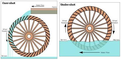
An undershot wheel is a vertically mounted water wheel with a horizontal axle that is rotated by the water from a low weir striking the wheel in the bottom quarter. Most of the energy gain is from the movement of the water and comparatively little from the head. They are similar in operation and design to stream wheels.
The word breastshot is used in a variety of ways. Some authors restrict the term to wheels where the water enters at about the 10 o’clock position, others 9 o’clock, and others for a range of heights.
The small clearance between the wheel and the masonry requires that a breastshot wheel has a good trash rack ("screen" in British English) to prevent debris from jamming between the wheel and the apron and potentially causing serious damage.
Breastshot wheels are less efficient than overshot and backshot wheels but they can handle high flow rates and consequently high power. They are preferred for steady, high-volume flows such as are found on the Fall Line of the North American East Coast. Breastshot wheels are the most common type in the United States of America
A vertically mounted water wheel that is rotated by water entering buckets just past the top of the wheel is said to be overshot. The term is sometimes, erroneously, applied to backshot wheels, where the water goes down behind the wheel.
A typical overshot wheel has the water channeled to the wheel at the top and slightly beyond the axle. The water collects in the buckets on that side of the wheel, making it heavier than the other "empty" side. The weight turns the wheel, and the water flows out into the tail-water when the wheel rotates enough to invert the buckets. The overshot design is very efficient, it can achieve 90%,
Nearly all of the energy is gained from the weight of water lowered to the tailrace although a small contribution may be made by the kinetic energy of the water entering the wheel. They are suited to larger heads than the other type of wheel so they are ideally suited to hilly countries. However even the largest water wheel, the Laxey Wheel in the Isle of Man, only utilises a head of around 30 m (100 ft). The world"s largest head turbines, Bieudron Hydroelectric Power Station in Switzerland, utilise about 1,869 m (6,132 ft).
Overshot wheels require a large head compared to other types of wheel which usually means significant investment in constructing the headrace. Sometimes the final approach of the water to the wheel is along a flume or penstock, which can be lengthy.
A backshot wheel (also called pitchback) is a variety of overshot wheel where the water is introduced just before the summit of the wheel. In many situations, it has the advantage that the bottom of the wheel is moving in the same direction as the water in the tailrace which makes it more efficient. It also performs better than an overshot wheel in flood conditions when the water level may submerge the bottom of the wheel. It will continue to rotate until the water in the wheel pit rises quite high on the wheel. This makes the technique particularly suitable for streams that experience significant variations in flow and reduces the size, complexity, and hence cost of the tailrace.
The direction of rotation of a backshot wheel is the same as that of a breastshot wheel but in other respects, it is very similar to the overshot wheel. See below.
Some wheels are overshot at the top and backshot at the bottom thereby potentially combining the best features of both types. The photograph shows an example at Finch Foundry in Devon, UK. The head race is the overhead timber structure and a branch to the left supplies water to the wheel. The water exits from under the wheel back into the stream.
A special type of overshot/backshot wheel is the reversible water wheel. This has two sets of blades or buckets running in opposite directions so that it can turn in either direction depending on which side the water is directed. Reversible wheels were used in the mining industry in order to power various means of ore conveyance. By changing the direction of the wheel, barrels or baskets of ore could be lifted up or lowered down a shaft or inclined plane. There was usually a cable drum or a chain basket on the axle of the wheel. It is essential that the wheel have braking equipment to be able to stop the wheel (known as a braking wheel). The oldest known drawing of a reversible water wheel was by Georgius Agricola and dates to 1556.
The earliest waterwheel working like a lever was described by Zhuangzi in the late Warring States period (476-221 BC). It says that the waterwheel was invented by Zigong, a disciple of Confucius in the 5th century BC.Chinese of the Eastern Han Dynasty were using water wheels to crush grain in mills and to power the piston-bellows in forging iron ore into cast iron.
In the text known as the Xin Lun written by Huan Tan about 20 AD (during the usurpation of Wang Mang), it states that the legendary mythological king known as Fu Xi was the one responsible for the pestle and mortar, which evolved into the tilt-hammer and then trip hammer device (see trip hammer). Although the author speaks of the mythological Fu Xi, a passage of his writing gives hint that the water wheel was in widespread use by the 1st century AD in China (Wade-Giles spelling):
In the year 31 AD, the engineer and Prefect of Nanyang, Du Shi (d. 38), applied a complex use of the water wheel and machinery to power the bellows of the blast furnace to create cast iron. Du Shi is mentioned briefly in the Hou Han Shu) as follows (in Wade-Giles spelling):
Water wheels in China found practical uses such as this, as well as extraordinary use. The Chinese inventor Zhang Heng (78–139) was the first in history to apply motive power in rotating the astronomical instrument of an armillary sphere, by use of a water wheel.mechanical engineer Ma Jun (c. 200–265) from Cao Wei once used a water wheel to power and operate a large mechanical puppet theater for the Emperor Ming of Wei (r. 226–239).
The ancient Greeks invented the waterwheel independently and used it in nearly all of the forms and functions described above, including its application for watermilling.Hellenistic period between the 3rd and 1st century BC.
The compartmented water wheel comes in two basic forms, the wheel with compartmented body (Latin tympanum) and the wheel with compartmented rim or a rim with separate, attached containers.sakia gear.
The earliest literary reference to a water-driven, compartmented wheel appears in the technical treatise Pneumatica (chap. 61) of the Greek engineer Philo of Byzantium (ca. 280−220 BC).Parasceuastica (91.43−44), Philo advises the use of such wheels for submerging siege mines as a defensive measure against enemy sapping.dry docks in Alexandria under the reign of Ptolemy IV (221−205 BC).papyri of the 3rd to 2nd century BC mention the use of these wheels, but don"t give further details.Ancient Near East before Alexander"s conquest can be deduced from its pronounced absence from the otherwise rich oriental iconography on irrigation practices.
The earliest depiction of a compartmented wheel is from a tomb painting in Ptolemaic Egypt which dates to the 2nd century BC. It shows a pair of yoked oxen driving the wheel via a sakia gear, which is here for the first time attested, too.Museum of Alexandria, at the time the most active Greek research center, may have been involved in its invention.Alexandrian War in 48 BC tells of how Caesar"s enemies employed geared waterwheels to pour sea water from elevated places on the position of the trapped Romans.
Around 300 AD, the noria was finally introduced when the wooden compartments were replaced with inexpensive ceramic pots that were tied to the outside of an open-framed wheel.
The Romans used waterwheels extensively in mining projects, with enormous Roman-era waterwheels found in places like modern-day Spain. They were reverse overshot water-wheels designed for dewatering deep underground mines.Vitruvius, including the reverse overshot water-wheel and the Archimedean screw. Many were found during modern mining at the copper mines at Rio Tinto in Spain, one system involving 16 such wheels stacked above one another so as to lift water about 80 feet from the mine sump. Part of such a wheel was found at Dolaucothi, a Roman gold mine in south Wales in the 1930s when the mine was briefly re-opened. It was found about 160 feet below the surface, so must have been part of a similar sequence as that discovered at Rio Tinto. It has recently been carbon dated to about 90 AD, and since the wood from which it was made is much older than the deep mine, it is likely that the deep workings were in operation perhaps 30–50 years after. It is clear from these examples of drainage wheels found in sealed underground galleries in widely separated locations that building water wheels was well within their capabilities, and such verticals water wheels commonly used for industrial purposes.
About the same time, the overshot wheel appears for the first time in a poem by Antipater of Thessalonica, which praises it as a labour-saving device (IX, 418.4–6).Lucretius (ca. 99–55 BC) who likens the rotation of the waterwheel to the motion of the stars on the firmament (V 516).central Gaul.Barbegal watermill complex a series of sixteen overshot wheels was fed by an artificial aqueduct, a proto-industrial grain factory which has been referred to as "the greatest known concentration of mechanical power in the ancient world".
In Roman North Africa, several installations from around 300 AD were found where vertical-axle waterwheels fitted with angled blades were installed at the bottom of a water-filled, circular shaft. The water from the mill-race which entered tangentially the pit created a swirling water column that made the fully submerged wheel act like true water turbines, the earliest known to date.
Apart from its use in milling and water-raising, ancient engineers applied the paddled waterwheel for automatons and in navigation. Vitruvius (X 9.5–7) describes multi-geared paddle wheels working as a ship odometer, the earliest of its kind. The first mention of paddle wheels as a means of propulsion comes from the 4th–5th century military treatise
Ancient water-wheel technology continued unabated in the early medieval period where the appearance of new documentary genres such as legal codes, monastic charters, but also hagiography was accompanied with a sharp increase in references to watermills and wheels.
The earliest excavated water wheel driven by tidal power was the Nendrum Monastery mill in Northern Ireland which has been dated to 787, although a possible earlier mill dates to 619. Tide mills became common in estuaries with a good tidal range in both Europe and America generally using undershot wheels.
Cistercian monasteries, in particular, made extensive use of water wheels to power watermills of many kinds. An early example of a very large water wheel is the still extant wheel at the early 13th century Real Monasterio de Nuestra Senora de Rueda, a Cistercian monastery in the Aragon region of Spain. Grist mills (for corn) were undoubtedly the most common, but there were also sawmills, fulling mills and mills to fulfil many other labour-intensive tasks. The water wheel remained competitive with the steam engine well into the Industrial Revolution. At around the 8th to 10th century, a number of irrigation technologies were brought into Spain and thus introduced to Europe. One of those technologies is the Noria, which is basically a wheel fitted with buckets on the peripherals for lifting water. It is similar to the undershot water wheel mentioned later in this article. It allowed peasants to power watermills more efficiently. According to Thomas Glick"s book, Irrigation and Society in Medieval Valencia, the Noria probably originated from somewhere in Persia. It has been used for centuries before the technology was brought into Spain by Arabs who had adopted it from the Romans. Thus the distribution of the Noria in the Iberian peninsula "conforms to the area of stabilized Islamic settlement".Spaniards, the technology spread to the New World in Mexico and South America following Spanish expansion
The type of water wheel selected was dependent upon the location. Generally if only small volumes of water and high waterfalls were available a millwright would choose to use an overshot wheel. The decision was influenced by the fact that the buckets could catch and use even a small volume of water.
Harnessing water-power enabled gains in agricultural productivity, food surpluses and the large scale urbanization starting in the 11th century. The usefulness of water power motivated European experiments with other power sources, such as wind and tidal mills.canals, put Europe on a hydraulically focused path, for instance water supply and irrigation technology was combined to modify supply power of the wheel.feudal state.
The water mill was used for grinding grain, producing flour for bread, malt for beer, or coarse meal for porridge.fulling mill, which was used for cloth making. The trip hammer was also used for making wrought iron and for working iron into useful shapes, an activity that was otherwise labour-intensive. The water wheel was also used in papermaking, beating material to a pulp. In the 13th century water mills used for hammering throughout Europe improved the productivity of early steel manufacturing. Along with the mastery of gunpowder, waterpower provided European countries worldwide military leadership from the 15th century.
Millwrights distinguished between the two forces, impulse and weight, at work in water wheels long before 18th-century Europe. Fitzherbert, a 16th-century agricultural writer, wrote "druieth the wheel as well as with the weight of the water as with strengthe [impulse]".Leonardo da Vinci also discussed water power, noting "the blow [of the water] is not weight, but excites a power of weight, almost equal to its own power".laws of force. Evangelista Torricelli"s work on water wheels used an analysis of Galileo"s work on falling bodies, that the velocity of a water sprouting from an orifice under its head was exactly equivalent to the velocity a drop of water acquired in falling freely from the same height.
The water wheel was a driving force behind the earliest stages of industrialization in Britain. Water-powered reciprocating devices were used in trip hammers and blast furnace bellows. Richard Arkwright"s water frame was powered by a water wheel.
The most powerful water wheel built in the United Kingdom was the 100 hp Quarry Bank Mill water wheel near Manchester. A high breastshot design, it was retired in 1904 and replaced with several turbines. It has now been restored and is a museum open to the public.
The biggest working water wheel in mainland Britain has a diameter of 15.4 m (51 ft) and was built by the De Winton company of Caernarfon. It is located within the Dinorwic workshops of the National Slate Museum in Llanberis, North Wales.
The largest working water wheel in the world is the Laxey Wheel (also known as Lady Isabella) in the village of Laxey, Isle of Man. It is 72 feet 6 inches (22.10 m) in diameter and 6 feet (1.83 m) wide and is maintained by Manx National Heritage.
During the Industrial Revolution, in the first half of the 19th century engineers started to design better wheels. In 1823 Jean-Victor Poncelet invented a very efficient undershot wheel design that could work on very low heads, which was commercialized and became popular by late 1830s. Other designs, as the Sagebien wheel, followed later. At the same time Claude Burdin was working on a radically different machine which he called turbine, and his pupil Benoît Fourneyron designed the first commercial one in the 1830s.
Development of water turbines led to decreased popularity of water wheels. The main advantage of turbines is that its ability to harness head is much greater than the diameter of the turbine, whereas a water wheel cannot effectively harness head greater than its diameter. The migration from water wheels to modern turbines took about one hundred years.
Water wheels were used to power sawmills, grist mills and for other purposes during development of the United States. The 40 feet (12 m) diameter water wheel at McCoy, Colorado, built in 1922, is a surviving one out of many which lifted water for irrigation out of the Colorado River.
Two early improvements were suspension wheels and rim gearing. Suspension wheels are constructed in the same manner as a bicycle wheel, the rim being supported under tension from the hub- this led to larger lighter wheels than the former design where the heavy spokes were under compression. Rim-gearing entailed adding a notched wheel to the rim or shroud of the wheel. A stub gear engaged the rim-gear and took the power into the mill using an independent line shaft. This removed the rotative stress from the axle which could thus be lighter, and also allowed more flexibility in the location of the power train. The shaft rotation was geared up from that of the wheel which led to less power loss. An example of this design pioneered by Thomas Hewes and refined by William Armstrong Fairburn can be seen at the 1849 restored wheel at the Portland Basin Canal Warehouse.
Australia has a relatively dry climate, nonetheless, where suitable water resources were available, water wheels were constructed in 19th-century Australia. These were used to power sawmills, flour mills, and stamper batteries used to crush gold-bearing ore. Notable examples of water wheels used in gold recovery operations were the large Garfield water wheel near Chewton—one of at least seven water wheels in the surrounding area—and the two water wheels at Adelong Falls; some remnants exist at both sites.Walhalla once had at least two water wheels, one of which was rolled to its site from Port Albert, on its rim using a novel trolley arrangement, taking nearly 90 days.water wheel at Jindabyne, constructed in 1847, was the first machine used to extract energy—for flour milling—from the Snowy River.
The early history of the watermill in India is obscure. Ancient Indian texts dating back to the 4th century BC refer to the term cakkavattaka (turning wheel), which commentaries explain as arahatta-ghati-yanta (machine with wheel-pots attached). On this basis, Joseph Needham suggested that the machine was a noria. Terry S. Reynolds, however, argues that the "term used in Indian texts is ambiguous and does not clearly indicate a water-powered device." Thorkild Schiøler argued that it is "more likely that these passages refer to some type of tread- or hand-operated water-lifting device, instead of a water-powered water-lifting wheel."
Around 1150, the astronomer Bhaskara Achārya observed water-raising wheels and imagined such a wheel lifting enough water to replenish the stream driving it, effectively, a perpetual motion machine.Arabic and Persian works. During medieval times, the diffusion of Indian and Persian irrigation technologies gave rise to an advanced irrigation system which bought about economic growth and also helped in the growth of material culture.
After the spread of Islam engineers of the Islamic world continued the water technologies of the ancient Near East; as evident in the excavation of a canal in the Basra region with remains of a water wheel dating from the 7th century. Hama in Syria still preserves some of its large wheels, on the river Orontes, although they are no longer in use.Murcia in Spain, La Nora, and although the original wheel has been replaced by a steel one, the Moorish system during al-Andalus is otherwise virtually unchanged. Some medieval Islamic compartmented water wheels could lift water as high as 30 metres (100 ft).Muhammad ibn Zakariya al-Razi"s Kitab al-Hawi in the 10th century described a noria in Iraq that could lift as much as 153,000 litres per hour (34,000 imp gal/h), or 2,550 litres per minute (560 imp gal/min). This is comparable to the output of modern norias in East Asia, which can lift up to 288,000 litres per hour (63,000 imp gal/h), or 4,800 litres per minute (1,100 imp gal/min).
The industrial uses of watermills in the Islamic world date back to the 7th century, while horizontal-wheeled and vertical-wheeled water mills were both in widespread use by the 9th century. A variety of industrial watermills were used in the Islamic world, including gristmills, hullers, sawmills, shipmills, stamp mills, steel mills, sugar mills, and tide mills. By the 11th century, every province throughout the Islamic world had these industrial watermills in operation, from al-Andalus and North Africa to the Middle East and Central Asia.crankshafts and water turbines, gears in watermills and water-raising machines, and dams as a source of water, used to provide additional power to watermills and water-raising machines.factory complexes built in al-Andalus between the 11th and 13th centuries.
The engineers of the Islamic world developed several solutions to achieve the maximum output from a water wheel. One solution was to mount them to piers of bridges to take advantage of the increased flow. Another solution was the shipmill, a type of water mill powered by water wheels mounted on the sides of ships moored in midstream. This technique was employed along the Tigris and Euphrates rivers in 10th-century Iraq, where large shipmills made of teak and iron could produce 10 tons of flour from corn every day for the granary in Baghdad.flywheel mechanism, which is used to smooth out the delivery of power from a driving device to a driven machine, was invented by Ibn Bassal (fl. 1038–1075) of Al-Andalus; he pioneered the use of the flywheel in the saqiya (chain pump) and noria.Al-Jazari in the 13th century and Taqi al-Din in the 16th century described many inventive water-raising machines in their technological treatises. They also employed water wheels to power a variety of devices, including various water clocks and automata.
A recent development of the breastshot wheel is a hydraulic wheel which effectively incorporates automatic regulation systems. The Aqualienne is one example. It generates between 37 kW and 200 kW of electricity from a 20 m3 (710 cu ft) waterflow with a head of 1 to 3.5 m (3 to 11 ft).
Overshot (and particularly backshot) wheels are the most efficient type; a backshot steel wheel can be more efficient (about 60%) than all but the most advanced and well-constructed turbines. In some situations an overshot wheel is preferable to a turbine.
The development of the hydraulic turbine wheels with their improved efficiency (>67%) opened up an alternative path for the installation of water wheels in existing mills, or redevelopment of abandoned mills.
The kinetic energy can be accounted for by converting it into an equivalent head, the velocity head, and adding it to the actual head. For still water the velocity head is zero, and to a good approximation it is negligible for slowly moving water, and can be ignored. The velocity in the tail race is not taken into account because for a perfect wheel the water would leave with zero energy which requires zero velocity. That is impossible, the water has to move away from the wheel, and represents an unavoidable cause of inefficiency.
The power is how fast that energy is delivered which is determined by the flow rate. It has been estimated that the ancient donkey or slave-powered quern of Rome made about one-half of a horsepower, the horizontal waterwheel creating slightly more than one-half of a horsepower, the undershot vertical waterwheel produced about three horsepower, and the medieval overshot waterwheel produced up to forty to sixty horsepower.
From the cross sectional area and the velocity. They must be measured at the same place but that can be anywhere in the head or tail races. It must have the same amount of water going through it as the wheel.
A parallel development is the hydraulic wheel/part reaction turbine that also incorporates a weir into the centre of the wheel but uses blades angled to the water flow.
The University of Southampton School of Civil Engineering and the Environment in the UK has investigated both types of Hydraulic wheel machines and has estimated their hydraulic efficiency and suggested improvements, i.e. The Rotary Hydraulic Pressure Machine. (Estimated maximum efficiency 85%).
These type of water wheels have high efficiency at part loads / variable flows and can operate at very low heads, < 1 m (3 ft 3 in). Combined with direct drive Axial Flux Permanent Magnet Alternators and power electronics they offer a viable alternative for low head hydroelectric power generation.
The Editors of Encyclopædia Britannica. "Waterwheel". Britannica.com. Encyclopædia Britannica, Inc. Retrieved 19 January 2018. |last1= has generic name (help)
Müller, G.; Wolter, C. (2004). "The breastshot waterwheel: design and model tests" (PDF). Proceedings of the Institution of Civil Engineers - Engineering Sustainability. 157 (4): 203–211. doi:10.1680/ensu.2004.157.4.203. ISSN 1478-4629 – via Semantic Scholar.
Wikander 2000, p. 395; Oleson 2000, p. 229It is no surprise that all the water-lifting devices that depend on subdivided wheels or cylinders originate in the sophisticated, scientifically advanced Hellenistic period, ...
Oleson 2000, pp. 235: The sudden appearance of literary and archaological evidence for the compartmented wheel in the third century B.C. stand in marked contrast to the complete absence of earlier testimony, suggesting that the device was invented not long before.
An isolated passage in the Hebrew Deuteronomy (11.10−11) about Egypt as a country where you sowed your seed and watered it with your feet is interpreted as an metaphor referring to the digging of irrigation channels rather than treading a waterwheel (Oleson 2000, pp. 234).
As for a Mesopotamian connection: Schioler 1973, p. 165−167: References to water-wheels in ancient Mesopotamia, found in handbooks and popular accounts, are for the most part based on the false assumption that the Akkadian equivalent of the logogram GIS.APIN was nartabu and denotes an instrument for watering ("instrument for making moist").As a result of his investigations, Laessoe writes as follows on the question of the saqiya: "I consider it unlikely that any reference to the saqiya will appear in ancient Mesopotamian sources." In his opinion, we should turn our attention to Alexandria, "where it seems plausible to assume that the saqiya was invented."
Adriana de Miranda (2007), Water architecture in the lands of Syria: the water-wheels, L"Erma di Bretschneider, pp. 48f, ISBN 978-8882654337 concludes that the Akkadian passages "are counched in terms too general too allow any conclusion as to the excat structure" of the irrigation apparatus, and states that "the latest official Chicago Assyrian Dictionary reports meanings not related to types of irrigation system".
Terry S, Reynolds, Stronger than a Hundred Men; A History of the Vertical Water Wheel. Baltimore; Johns Hopkins University Press, 1983. Robert, Friedel, A Culture of Improvement. MIT Press. Cambridge, Massachusetts. London, England. (2007). p. 33.
Davies, Peter; Lawrence, Susan (2013). "The Garfield water wheel: hydraulic power on the Victorian goldfields" (PDF). Australasian Historical Archaeology. 31: 25–32.
Gies, Frances; Gies, Joseph (1994). Cathedral, Forge, and Waterwheel: Technology and Invention in the Middle Ages. HarperCollins Publishers. p. 115. ISBN 0060165901.
Quaranta Emanuele, Revelli Roberto (2015), "Performance characteristics, power losses and mechanical power estimation for a breastshot water wheel", Energy, Energy, Elsevier, 87: 315–325, doi:10.1016/j.energy.2015.04.079
Reynolds, T.S. (1983) Stronger Than a Hundred Men: A History of the Vertical Water Wheel, Johns Hopkins studies in the history of technology: New Series 7, Baltimore: Johns Hopkins University Press, ISBN 0-8018-2554-7
Wilson, Andrew (1995), "Water-Power in North Africa and the Development of the Horizontal Water-Wheel", Journal of Roman Archaeology, vol. 8, pp. 499–510

Undershot wheel. Colonial-era mill wrights figured that this type of water wheel transmits water power at 30% efficiency while overshot wheels are 75% efficient and breast wheels are 65%. But this wheel is generating 100% more energy than before, so win-win

Please Note: I have not reproduced all of the photos mentionedon the pages in these sections. I have repoduced some photos in the "images"section, and some in section called "Water Wheel Albums," seeFitz Water Wheel pages. For a complete text and all the photos, please ordera reprint copy from the Mill Bookstore of the
The Fitz I-X-L Steel Overshoot Water Wheel is the product of three generationsof unbroken experience in the design and manufacture of water wheels. Ithigh efficiency is due to its correct mechanical principles and to its carefuldesign and construction.
The manufacture of Overshoot Water Wheels was begun by Samuel Fitz, in Hanover,Pennsylvania., U. S. A., in the year 1840. The industry has been carriedon continuously since that time on the same site under the management ofthe son and grandson of the original founder.
The earlier Fitz Wheels were, of course built of wood. A number of ordersare still being received for iron parts for wooden water wheels, as describedlater in this booklet, but by far the greater part of the business donetoday is the manufacture of the all-steel Overshoot Water Wheels, in whichthe company specializes.
The real credit for the invention of the modern Steel Overshoot Water Wheeland for its development into its present highly efficient form must be givento the late John Fitz. [John Fitz, Inventor and Manufacturer. Born April15, 1847 - Died, April 12, 1914. "He originated the modern Steel OvershootWater Wheel, and rescued from oblivion one of the most useful principlesof Hydraulics."] Very early in his business career he realized thegreat possibilities of this type of water wheel and he devoted the greaterpart of his life to the study of its principles and the improvement of itsefficiency. How well he succeeded is shown by the high regard in which theSteel Overshoot is held today. In spite of this, we have not relaxed outefforts for further improvements, but are constantly striving for stillbetter results in every detail of construction.
The knowledge and experience accumulated by out organization during itslong career in the water wheel business forms an ever greater asset thanout well equipped modern factory. Most of out employees have grown up withus, and our millwrights and mechanics have been trained in this line fromearly youth. In reckoning with your water power problems, therefore, wehave a vast fund of practical experience to draw from and we are glad toplace this freely at the service of out customers.
The Overshoot Water Wheel derives its power directly from the force ofgravity. The illustration shows the principle upon which it works. The weightof the water which is admitted to the buckets, loads one side of the wheel,causing it to revolve.
The water should be applied to the top of the wheel at a point about teninches back of the vertical center line, so that the buckets will fill upjust as they pass over the topmost point of the wheel.
The diameter of an overshoot wheel should be from 2 1/2 to 3 feet less thanthe total fall available. By total fall, we mean the vertical distance fromthe surface of the water in the fore bay or "tank" above the topof the wheel, down to the surface of the water in the tail race or dischargecanal, below the bottom of the water wheel.
Wheels of all types were formerly built of wood. Many picturesque examplesof this method of construction are still to be found in rural districts.The overshoot wheel possessed so many advantages that it soon displacedthe other early types of water wheels. Even with all its crude design andill-suited material, the wood overshoot still persists as a strong competitorof the modern small turbine.
The field of the Overshoot Wheel lies in the development of small powers.It is not suitable for use in very large developments on account of theincrease in size and weight of the wheel as the head and discharge are increasedbeyond certain limits. It can be built in any diameter needed up to 60 feetand in any width desired up to a capacity of 3,000 cubic feet per minutein single units.
The power of an overshoot wheel depends upon both the diameter of the wheeland the width of the wheel. The larger the diameter of an overshoot wheel,the more power it will develop with the same amount of water. The widerthe wheel is made, the more water it will accommodate. The relative powerof two wheels of the same diameter is of course in direct proportion tothe amount of water each wheel is capable of using, if other conditionsare equal. The question of determining the proper size wheel to use forany particular location is one which should usually be left to the judgmentof the builder of the wheel. We do not publish any list of sizes of wheelsin this booklet for the reason that we prefer to have our customer giveus the data, so that we, ourselves, can select the size of wheel he oughtto have.
For any location within the range of its capacity, the overshoot type ofwheel possesses certain decided advantages, over all other types of waterwheels, viz.:
The extent to which any overshoot wheel makes use of these advantages dependslargely upon design of the wheel, its accuracy of construction and the materialof which it is made. The Fitz Steel Overshoot Water Wheel makes use of thesame basic principles as the old wood overshoot, but its superior designenables the Fitz Wheel to develop more than 90% efficiency as compared withthe 60% to 70% efficiency of the wood wheel. The reasons for this are setforth in detail later on in this booklet under the heading "Comparisonwith wood wheels." The efficiency of the Fitz Wheel is not a matterof opinion or guess work. Our wheels are rated according to the resultsshown by rigid test on Hydraulic Testing Flumes.
Developing an efficiency of 90% or more, the Fitz Steel Overshoot is vastlymore efficient than any other type of water wheel known. In the smallerinstallations especially, where the overshoot most frequently competes witha turbine, it is doubtful whether the turbines ever operates with an efficiencyhigher than 70%. It is true that many turbine builders claim high efficienciesfor their wheels, but every experienced turbine user has good reason toknow how far the turbines themselves fall short of their makers" claimswhen confronted with actual running conditions. In every case, where theamount of fall and quantity of flow is suitable for our type of wheel, aFitz Overshoot will develop at least one-third more power than any turbineworking under similar conditions, or 25% more than the best new wood wheelthat can be built.
The above statements are made without prejudice to the turbine type of waterwheel, for we build a turbine wheel ourselves that ranks fully equal tothe best on the market. We are just as glad to sell a turbine wheel as weare to sell an overshoot where the conditions are suitable for a wheel ofthat type, but we will not furnish either kind for a location where we knowthat out customers" interests require the other.
The development of the overshoot water wheel into its present state ofunrivalled efficiency has been the results of many years of thought andeffort. Founded in its present location nearly ninety years ago, this firmhas been building water wheels continuously during all that time, but ithas never ceased to improve and modernize its product.
Up until the advent of the modern Fitz Steel Overshoot Water Wheel an efficiencyof 60% to 70% was considered remarkably good for small water power plant.Today, practically every recent text-book on hydraulics concedes an efficiencyof 90% or more to the "modern steel overshoot water wheel when properlyconstructed." Proper construction means "Fitz Construction,"for no other make of water wheel has approached this high efficiency. FitzWater Wheels form part of the equipment of some of the greatest engineeringcolleges and universities of the world. They have been adopted by many railroadsand by many of the leading engineering firms in this country for use whereverhigh efficiency and perfect reliability are the essential requirements ina small water power development.
A range of four hundred per cent in variation of the amount of water suppliedto this water wheel showed a difference of only 5% in the efficiency ofthe wheel. We quote as follows from an article in the "EngineeringNews" of January 2, 1913, by Prof. Carl R. Weidner, Instructor in HydraulicEngineering at the university of Wisconsin:
"To engineers familiar with the variation in efficiency of the turbineat part gate, a glance at the curves obtained from the Wisconsin experimentswill be convincing as to the superiority of the overshoot wheel in respectto its adaptability to varying discharge."
"The result of the experiments show high efficiencies under a widerange of operating conditions. Reliable test of turbines have been reportedyielding as high as 89% efficiency but it is rarely that this figure isobtained in an actual installation. In the smaller plants, especially, wherean overshoot wheel would be capable of competing with a turbine, it is doubtfulwhether the turbines operate with an average efficiency higher than 70%."
"Laboratory test of a machine, when properly interpreted, undoubtedlyhave great value, but it must be borne in mind, that any test so made representsresults under the exact conditions of the test. The conditions under whichthe Wisconsin experiments were performed approached practical conditionsvery closely. The wheel tested was of a standard pattern taken from thestock of the manufacturers. The structure features are simple, and noneof these features, of the wheel itself, were changed during the tests. Theresults should, therefore, be readily duplicated in actual service, if thewheel is set properly."
The published test reports of the university of Wisconsin show the ten footdiameter Fitz Wheel above illustrated, mounted on out bronze lined bearings,yielded an efficiency of 89%, on the water wheel shaft.
Later tests of this same wheel, made under the same supervision but withthe mounting changed to our self-aligning ball bearings, showed an efficiencyof 92%. [Note this was the only water wheel efficiency testing done andreport published in this century]
The power developed at any water power installation depends on three factors,viz.: The volume of water in the stream, the amount of fall and the kindof water wheel used. The first two factors are usually determined by thenatural conditions and are nearly always developed to the greatest practicableextent. They fix the potential or theoretical power. The water wheel isthe medium by which the potential or possible power is converted into actualprofit-earning power.
There is a great difference in water wheels. Failure to realize this facthas caused many water power projects to result in disappointment. Afterspending perhaps, thousands of dollars on the dam, race-way, flume, excavating,etc., to develop a power, it is a very poor policy to sacrifice a largepart of the returns by putting in a wasteful, inefficient water wheel. Awater wheel of low efficiency may only develop half, or less than half,the possible power of the location. That means a sacrifice of one-half theearnings capacity of the plant. And that is just what nineteenths of theturbines and wood wheels in existence are doing for their owners. The remainingtenth are doing better than this but not one of them is giving anythinglike the actual power it should give.
A man with a valuable water power cannot afford to take an inefficient wheelas a gift. His water power is valuable just in proportion to its earningcapacity, and its earning capacity is regulated by the amount of power developed.A wasteful water wheel cuts down the value of the whole plant in proportionto the amount.
A water power plant usually represents not only the investment of a considerablesum of money in the dam, race-way, flume, tail race, etc., but also in thevalue of the factory which it operates, since that can earn but little withoutthe power. The cost of the best water wheel on earth is but a fraction ofthe value of the entire plant which depends on it. Too much care cannotbe used in the selection of a water wheel. Only the best and most efficienton the market should be considered. That is the only wise and economicalpolicy.
By repeated tests the Fitz Overshoot Water Wheel has shown that it willdevelop at least 33 1/3 more power than the best turbine made using thesame amount of water. We are well aware that some turbine builders claimfrom 80% to 85% efficiency for their wheels and pretend that this is provenby their records in the testing flume. Such claims are absurd. It is truethat a few turbines have given a little over 80% efficiency in the laboratorywhen tested at full gate, but it must be remembered that these were largewheels built regardless of expense and working under the most favorableconditions known. Even in the case of the large turbines, the practicalvalue of these tests may be seen from the fact that no two wheels of thesame size and same make would give the same efficiency, and often the samewheel, when tested at different times, would vary considerably. Small turbines,such as out wheel competes with, have never shown good results even in laboratorytest.
It is well known that conditions are much less favorable to turbines inactual use that to those in the testing flume, and that when you buy a turbinefrom any builder you don"t get near as good a wheel as the one he buildsespecially to be tested. We know it to be a fact that there is no turbinebuilt today that will develop over 65% to 70% efficiency in actual use,and the great majority fall much below this. See the extracts on the followingpages from some leading reference works in regard to this.
But it is not enough to merely consider the efficiency of a wheel with afull head of water. It is just as important to know how a wheel will actwith a diminished head or scanty supply of water. No stream of water isof the same size at all seasons and a wheel that is not adaptable to varyingconditions is useless a large part of the year. This is the point whereall turbines, despite the claims of their makers, fail absolutely, for unlessthey are run a full gate, or nearly so, they will do very little work. Thesteel overshoot is a model wheel in this regard, as in every other respect,for it will run just as economical at one-fourth gate as at full gate, whilewhen water is plentiful, it can be crowded far beyond its normal capacity.
The Fitz Wheel depends only to a small extent upon pressure for its power.It can adapt itself to a wide range of heads. This feature is especiallyvaluable where water is scarce and a large pond is used to store the waterover night. Every one knows how unsatisfactory it is to use a turbine whereyou have to run by heads. Since the turbine depends upon the pressure ofthe water, when the head diminishes naturally the speed diminishes and alsothe power. With the Fitz the head can be drawn down almost to the bottomof the race without affecting either the power or the speed.
Besides these most important consideration of high efficiency and adaptabilityto varying conditions, there are five other points that an ideal wheel shouldpossess, viz.:
These points are only to be found in the Fitz Steel Overshoot Water Wheel.The large buckets cannot possibly become clogged with leaves, sticks, oranything else, like turbine buckets, for whatever goes through the gatewill pass over the wheel freely. Ice, which causes so much trouble withwood wheels and turbines, has but little effect upon the steel overshoot.It cannot form on the wheel as long as it is in motion, for the thin steelreadily acquires the temperature of the water passing over it and remainsabove the freezing point. Even should any ice form on the wheel while standing,a few strokes with a hammer will cause the wheel to ring like a bell andwill shiver the ice all off, for there is nothing for it to cling to.
The gate of our wheel is simplicity itself. It is tight beyond comparisonwith turbine gates. The balance of the wheel is very accurate. The wheelcan be easily turned by one hand no mater how large it is. As for durability,it leaves nothing to be desired. The first wheels we ever built are stillrunning and are in first-class condition right now.
Back water, which will soon stop a wood overshoot, has very much less effecton the Fitz wheel. We usually calculate out wheels to accommodate from one-fourthto one-half more water than the normal volume of the streams which drivethem. Consequently at flood periods more water can be used on the wheel,thus overcoming the loss of head in back-water.
A careful consideration of the above facts must lead the conclusion thatthe Fitz Steel Overshot is not only the best water wheel on the market butalso the cheapest, for it gives much the best value for the money expended.This wheel utilizes every bit of water to its fullest possible extent. Thevalue of the increased power alone, that it yields, may be worth more everyyear than the whole cost of the water wheel, to say nothing of its greaterdurability and more satisfactory service.
The Fitz Steel Overshoot Water Wheel is built entirely of iron and steel.Its high efficiency is due to its correct principles of design and to thehigh class workmanship and material used in its construction.
The word "Overshoot" is simply our arbitrary spelling which weadopted some time ago to distinguish our wheel from the ordinary "overshot"water wheel. For the sake of brevity our wheel is sometimes referred toby its old name, "The I-X-L," or often as "The Fitz Wheel."
We do not wish to convey the impression that the Fitz Overshoot is the bestwheel for all locations or for all conditions. Our field is in the developmentand improvement of small water powers. By small water powers we mean thosehaving falls of less than sixty feet and volumes of water smaller than 3,000cubic feet per minute for single units of wheels. Even within those limits,there are certain conditions to be met with occasionally which call forother types of water wheels. Within its own field, however, there is noother type of water wheel in the world that can compete with the Fitz Wheel.Put your conditions up to our engineers and let us tell you what we cando for you. We will guarantee in every case to greatly improve your poweror to let it alone.
The site of an overshoot wheel depends largely upon the situation, but weusually make the diameter about 2 1/2 feet less than the amount of the actualworking head.
The force of the water above our wheel is not lost but acts by its impulseupon the wheel just as it act on a turbine or impulse wheel. In other typesof overshoot wheels this force is almost entirely wasted but the shape ofour buckets and our method of applying the water to the wheel enable usto utilize this impulse. As will be seen from the cut on page eighteen,the water spurts across our smooth steel chute at a tangent to the crownof the wheel. It enters the buckets a little back of the vertical centerline of the wheel and glides along the curved part of the bucket, strikingthe heel of the bucket at right angles to the radius of the wheel drawnto that point. Thus its power is communicated to the wheel in the directionbest adapted to produce the greatest effect.
The curve of the bucket is not the same in all sizes of wheels. It is variedto suit the particular requirements. Proper allowance is made in all casesto permit the exit of air from the bucket when water is entering. The shapeof the bucket is such as to retain the water until all possible power istaken from it. The water is actual retained in the buckets almost to thelevel of the surface of the tail race.
The housing if the steel overshoot, instead of coming flush with the bucketsas in a wood wheel, are extended so as to prevent any water splashing overthe sides. Thus not a drop of water is wasted and the water is dischargedin the tail race with all its power extract. Compare the calm stream flowingfrom the overshoot wheel with the rushing torrent discharged by the turbineand you will see one of our strongest points. Mighty few small turbinesget more than 60% or 65% of the energy out of the water that they use, andthe momentum of the tail race represents a considerable part of the remaining35% or 40%.
Practically no power is wasted by friction in the bearing of our wheels.Fitz Wheels are so perfectly balanced and run with so little friction thata little child can turn the largest wheel we ever built, with one hand.Thus we are able to transmit undiminished to the jack shaft, nearly allof the energy we have extracted from the water.
With each wheel we usually furnish our "water-tight" iron gateand steel "chute." Our iron gate is a very valuable feature. Onsmall streams in very dry weather, it is essential to save all the waterpossible. A wood wheel or a turbine will often allow enough water to leakaway at night through its defective gates, to run a Fitz Overshoot for severalhours a day. The Fitz gate consists of two parts, a smoothly planed ironframe, and a movable slab which is both planed and scraped to insure a veryaccurate fit. It is tight and at the same time it is almost perfectly trouble-proof.The chute is the steel trough which carries the water from the gate to thebuckets of the wheel. This piece is necessary in every case, in order toapply the water to the wheel at the proper tangent.
The object of all wheels is to utilize the weight of falling water and todevelop power thereby. The Fitz Wheel does this in the most direct mannerand therefore with the least loss. Turbines and other wheels, aim to developtheir power in an indirect manner by reaction or impulse caused by pressure.To give even moderately good results they must be geared to run at certainspeed, under a certain pressure and using a certain amount of water. Sincethe overshoot depends mainly on the positive weight of the water and onlyin a small degree on impulse, it can run fast or slow, with high head orlow head, at full gate or fractional gate with equally high efficiency,and developing power in exact proportion to the amount of water used.
The motion of the Fitz Overshoot is slow. In order to drive fast runningmachinery the wheel should be equipped with suitable gearing. Later on inthis booklet, the reader will find a number of plans showing approved methodsof connecting up various kinds of machinery to our wheels.
Fitz (I-X-L) Steel Overshoot Water Wheels are shipped "knocked down"in sections easy to handle. The rim or "buckets" comes in fromeight to twenty sections, according to the diameter of the wheel. Everypiece is carefully marked or numbered and we furnish full printed instructionsfor assembling with each wheel, as well as a blue-print drawing showingthe setting. The arms are numbered to suit the pockets of the flanges towhich they belong. The sections of the rim and the segments of the gearare likewise numbered to correspond with their respective positions.
We can furnish a skilled mechanic from our factory to install our wheelswhen wanted, but our careful method of marking an the perfect "fit"of each piece makes it very easy for the purchaser to install the work himself.
The bolts and rivets used in our wheels are selected with great care. Theyare absolutely the best that can be bought. For specially heavy servicewe make our bolts out of nickel-chrome-vanadium steel. Patented Nut Locksare used wherever necessary. Our gears are cast from semi-steel in our ownfoundry and are much stronger and tougher that cast gearing.
With a large stream of clear water which never varies in volume, andwith a good fall, a well made turbine will work very satisfactorily. Itis true that the efficiency of small turbine water wheels is always overrated,very few of them in practical use giving over 60% of the power they shoulddevelop, but of course where there is an abundance of water it is not necessaryto be economical. But on a light stream, or wherever it is desirable toget the full power from the water, they are failures. The capacity of aturbine is unhangable. If you have more water than you need, it is wasted.If less, it will hardly turn the wheel. The reverse is true of the Fitz,as its adaptability to varying conditions is one of its strongest points.When water is scarce it will develop the full percentage of power, whilewith an abundance of water the wheel can be crowded far beyond its normalcapacity.
A turbine depends for its power upon the reaction or impulse of the waterdischarged under pressure of the working head. The pressure is due to theweight of the water and is proportional to the working head of water overthe wheel. The higher the head the greater the pressure, and hence the velocityof the water discharged. The wheel must run at a certain proportionate velocity,the buckets must be curved at a certain angle, and the water must be dischargedin a certain volume in order to do good work. All these points must be rightin order to obtain even 60% to 70% efficiency. they are fixed by the volumeof the stream to be used and the amount of water secured. Most streams areconstantly varying in volume and it is impossible to supply the wheel withthe same amount of water or to keep up the same head, so the conditionsare seldom favorable for a turbine to reach its maximum efficiency. It cannotadapt itself to the changed conditions of diminished supply or lowered head.Consequently in dry weather, when economy of water is most necessary, theturbine is most wasteful, and will do practically no work at all.
Of course we are aware that all turbine manufacturers table their wheelsat 80% efficiency, or higher, and that nearly every one claims that he alonehas solved the impossible problem of making a turbine to work equally wellat partial gate as at full gate. These foolish claims are a result of conditionsestablished many years ago. Since it is the universal custom, the turbineman who did not make such claims could get no hearing for his wheel. Thecustomer has usually no means of testing his wheel and does not realizethe outrageous discrepancy between the power promised by the turbine men,and the results actually attained.
An interesting side light on some of the losses which make impossible thehigh efficiency of any turbine wheel is shown by the following extract froma book entitled "Turbine Water Wheel Tests," written by RobertE. Horton, and published (1906) by the United States Geological Survey,("Water Supply and Irrigation Paper No. 180") page 22:
Remember that these losses occur in every turbine. Some of them are quiteimportant. Take for instance the one item of leakage through only one ofthe clearance spaces. Even a perfectly new turbine wheel has some clearancebetween the runner and the case. Water escaping through this opening undervery heavy pressure and carrying sand and grit, soon enlarges this clearanceuntil it is 1/4" wide or more. Take a 20" turbine inch 24 foothead. That means a stream of water 3.4" thick by 63" (the circumferenceof the wheel) under a pressure of 24 feet escaping all the time withoutever going through the buckets at all. The gate leakage is also a heavyitem of loss.
The Fitz Steel Overshoot Water Wheel will deliver at least a third morepower than the best turbine using the same amount of water, because it developsits power by utilizing the weight of the water in the simplest and mostdirect manner possible, instead of indirectly through impulse or reaction,as in the turbine. The water is received from the fore bay in such a manneras to utilize as much as possible of the impulse due to the head in thefore bay, and is retained by the correctly curved water tight buckets untilit reaches the center again at the bottom, where it is discharged in a calmstream with all the energy extracted. There is no occasion for loss of powerin this process; no splashing, no leaking or spilling too soon.
If half the normal quantity of water is used on a Fitz Overshoot wheel itwill develop half the power, or one fourth the power with one fourth thewater, thus showing that its efficiency is unimpaired by the changed conditions.No power is lost by friction, for a child can turn our largest wheel withone hand.
A great deal of trouble is experienced by turbine users in hilly or sandylocalities where the frequent floods and freshets wash down great quantitiesof sand and grit, which are very hard on their wheels. The leaves, sticksand other trash which get into the buckets and choke up the narrow ventsare also a constant annoyance and frequently stop the wheels. The turbineflume, if built of wood, requires constant attention and repairs. The gatesare invariably leaky after a few months" use and waste a great deal of water.The complicated construction of some turbines make them particularly aptto get out of order, but they all give more or less annoyance in this regard.
None of these troubles have any effect whatever upon the Fitz Steel Overshoot.There is nothing about it to break or get out of order. Every part is exposedto view and easily accessible, but the only attention required is to oilthe bearing occasionally. The gate is as near perfection as possible foranything which has to work in water, and owing to its simple constructionwill remain for years just as tight as the day it was put in. The largebuckets cannot possibly choke up no matter how dirty the stream is, foranything that will pass through the gate will pass over the wheel withoutthe slightest injury.
The condensed experience of thousands of water power owners shows that ifyou have more water at all seasons of the year than you can use, so thateconomy of water is no object to you, then you can use a turbine satisfactorily,provided you are not greatly troubled with sand or trash in your stream.But if you want to get all out of your water power that there is in it;to develop the highest efficiency at all times, no matter how low the wateris; if you want durability and freedom from repairs; economy and satisfactoryresults, then the Fitz Steel Overshoot Water Wheel is the only wheel onthe market worthy of your consideration.
The wood overshoot still survives as an active competitor of the smallturbine in some parts of the country. On a light stream, as well made woodwheel will often give better results than a turbine, but it always fallsfar short of getting the full possible power from the water.
Wood is not a fit material to use in building a water wheel. A high efficiencywheel must be made of metal. Wood overshoots have been built for centuries,but up until the advent of the Fitz, an efficiency of 75% was consideredthe limit for an overshoot wheel of any kind. Mighty few wood wheels everapproach that efficiency today.
The buckets of a wood wheel cannot be shaped to a suitable curve to receiveand discharge the water properly. A wood wheel is invariably out of balanceand its jerky motion is destructive to good results from the machinery itoperated. The constant swelling and drying of the wood soon causes all partsto get loose; the buckets leak; and a considerable proportion of the energyis wasted.
In a steel wheel, the buckets can be shaped to suit the design required.The Fitz steel bucket is shaped so as to receive the water at the crownof the wheel with the least possible shock. It retains the water to a pointjust a little above the level of the tail race. In other words, the watergets to work on a Fitz wheel at least three buckets earlier than it doeson other wheels, and it stays on the wheel from three to ten buckets longer,depending upon the diameter of the wheel.
A wood wheel gets no benefit from the head of water over the top of thewheel. In order to put the water into the thick straight, wood buckets,the chute is generally slanted a good deal and the water is allowed to "drop"on to the wheel in the manner illustrated on page 31. The water consequentlystrikes the wheel at an ineffective angle and its energy is dissipated inshock, instead of being communicated to the wheel.<


 8613371530291