
overshot wheel pricelist

We have a number of options for coating a metal water wheel. We will thoroughly discuss your plans with you and recommend the best coating solution. Please see our section on Wheel Coating Options.
Site Installation:With water wheels that are eight feet or more in diameter, we suggest that we provide our personnel to help with the site installation. Smaller wheels generally can be assembled at the site and installed by your personnel. We cannot guarantee assembly if we are not there for the installation.
Shipping: We ground ship throughout the United States. Our engineering associate in Italy is prepared to supervise assembly and installations overseas. We negotiate the best price and reliable logistics management for timely delivery of your waterwheel to your installation site.
The Waterwheel Factory closely collaborates with Designers, Mill Owners, Architects, Property Developers, General Contractors and Property Owners on a personal basis to assure that each water wheel project is optimally managed from conception to final installation.
Send us your buildings CAD drawings and we will work with them to include the details needed to support your waterwheel for you, your builder and permit office.

One final note: The following article describes a homemade overshot water wheel set up to do only one thing . . . pump water from a spring to a set of farm buildings 100 feet above. If you’re more interested in learning how to use the same kind of wheel to generate electricity, see the article, schematic drawing, and photographs of Thomas Oates’ water-wheel powered DC electrical system in MOTHER NO. 24. That piece was also reprinted in The Handbook of Homemade Power. — The Editors.
One very successful example of this “back to basics” trend is the water wheel-powered water pump now in operation on the Robert Wooding farm near Halifax, Virginia. The pump-powered by a home designed and home-built 6 1/2-foot, steel water wheel which, in turn, is spun by water from a stream on the family farm shoves 1,440 gallons of pure spring water 100 feet uphill every 24 hours. And, since the system was set up, it hasn’t cost the Woodings anything for its tireless round-the-clock operation . . . except a few cents for lubrication.
“There are three things I especially like about my wheel,” says Bob blooding. “One, unlike the hydraulic ram pumps featured several times in MOTHER, it doesn’t use gallons and gallons of our drinking water just to pump a few gallons up the hill. Two, the overshot design of our wheel makes very efficient use of the small stream we tap for power. And, three, there’s not a whole lot of banjo work to a rig like this once you’ve got it going. We spent a little time and money setting our system up, to be sure, but it’s been practically maintenance-free ever since. About all we do is give its bearings a shot of grease two or three times a year.”
The Woodings were fortunate enough to have a picturesque stream on their property (the first and most obvious requirement for any water-power system!) . . . but that’s as far as their luck went. At no single spot along the creek was there enough “fall” to turn the 6 1/2-foot overshot wheel that Bob figured on installing.
The ideal location, of course, for an overshot water wheel (which must be positioned in a stream at a spot where the water abruptly drops at least as far as the wheel is tall) is a natural rapids or waterfall. If, like the Woodings, you find yourself working with a stream that has no such abrupt natural drop, however, you’ll have to do what the Woodings did: Build your own man-made waterfall . . . which, as we all know, is commonly called a dam.
(NOTE: The reprinted series of five articles from Popular Science mentioned at the beginning of this piece contains everything you need to know to calculate the flow and call of a stream, design several kinds of dams, build and install an overshot wheel, and otherwise fabricate and operate a farm- or homestead-sized water-power system. — The Editors.)
“We needed about a seven-foot fall for our 6 1/2-foot-tall wheel,” Bob blooding remembers, “so we built a three-foot-tall dam . . . and then flumed the water from the top of that dam to a spot 120 feet further downstream where the creek’s banks were an additional tour feet lower. The dam’s height of three feet plus the additional four feet of drop we picked up by running our flume that tar added up to the seven feet of fall, or head, that we needed for our wheel.”
The Woodings’ flume is a combination of approximately 85 feet of four-inch aluminum pipe feeding into an additional 46 1/2 feet of wooden trough measuring six inches deep by six inches wide. (The aluminum pipe, which extends about a foot and a half into the trough, can be lifted out and set into a curved metal deflector which routes its water back into the stream whenever the Woodings want to stop the wheel.)
Traditional flumes for homestead water wheels, of course, were of all-wood construction. But Bob Wooding decided to use rot-free, corrosion-free aluminum pipe for the first two-thirds of his wheel’s feeder line, where the flume had to extend into the water and then run underground. The pipe’s inlet is covered with a screen to keep the line from becoming clogged with misguided leaves, turtles, and crawfish. Care was also taken to position the opposite (wooden) end of the flume so that its discharge of water would hit the exact top-center of the overshot wheel.
Although the blooding family’s water system for their house, stables, and swimming pool is powered by the stream on their farm . . . the actual water which flows through that system comes from a clear, cool, pure spring. This spring, too (just like their dam), is located about 120 feet from the overshot wheel and pump that is the heart of the whole hookup. So, in addition to the flume which carries the “driving” water from the dam to the wheel, another one-inch pipe was laid to carry the “driven” water from the spring to the pump that is installed next to (and driven by) the wheel.
When you buy a manufactured water wheel, a large portion of the purchase price goes to pay for the equipment’s design. It follows, then, that you can save yourself a sizable chunk of cash by working up the specifications for your own wheel . . . and that’s exactly what Bob Wooding did.
Actually, this isn’t as difficult as you might think. To extract maximum power from any given flow of water with an overshot wheel is largely a matter of calculating the proper depth and angle of the buckets placed around the wheel’s rim (ideally, each bucket must be completely filled at top center and then carry its load of water without spilling a drop until just the instant it passed bottom center . . . but anything even remotely approaching this ideal will handle the job satisfactorily in most homestead applications).
(EDITORS’ NOTE: If you scale up the drawings shown here and use them to construct a wheel ranging anywhere from two feet up to 20 feet in diameter — and if you work carefully and in a craftsman-like manner — the chances are good that your finished wheel will work well enough to make you pretty dang proud of yourself. If you really want to go for the finer points of maximum efficiency, however, you can work from the more detailed dimensions and angles given in the full-page drawing of an overshot wheel on page 31 of MOTHER N0. 14.)
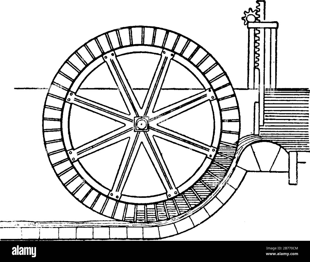
After drawing up his design (complete with “dribble” hole in the bottom of each bucket, so that the wheel is self-draining when not in use!), Bob had the individual parts for his water wheel prefabbed by the Carolina Steel Company in Greensboro, North Carolina. A Richmond, Virginia representative for the firm says that the 3/16 inch steel plate used in the 980-pound assembly’s 37 eight-by-twelve-inch buckets, its five-inch-wide rim, and its one-foot-wide sole plate would currently cost about $130. You can add on another $70 for burning, forming, and welding the metal. (These prices, of course, will vary in different parts of the country and — as time goes on — are sure to escalate right along with the price of everything else.)
The hubs for the Wooding wheel were pretty much “Chinese copied” from the hubs manufactured years ago by the now-defunct Fitz Water Wheel Company of Hanover, Pennsylvania. Bob had them cast at a local foundry from a wooden pattern that he made himself, and the materials and labor for the raw castings set him back only $25. A nearby machine shop then bored out the hubs on a lathe, cut keyways into the bores, and made up the pair (each half of the set contains six 3/8 inch by 2 inch spokes) of spokes for the wheel . . . all for only $60 complete.
Once he had all the components for his wheel prefabbed and in hand, there was nothing for Bob Wooding to do but assemble the power unit. “I used calipers to measure and remeasure the spaces around the rim for my buckets until I had them exact to the width of a pencil mark,” Bob says. “Then I tacked the buckets in place all the way around and rechecked everything before I finally welded them in permanently. If you try to finish-weld each one as you go without tacking everything together first, you know, you can get off kilter and warp the whole wheel.”
Every one of the six “ears”, or extensions, on each of the two hubs has a recessed area 3/8 inches deep by two inches wide by four inches long on its inside surface for a spoke to set into. This end of each spoke is held firmly in place with two 7/16 inch galvanized bolts, nuts, and lock washers. The other ends of the spokes are welded to the outside faces of the wheel’s rim . . . as you can see in one of the accompanying photos.
It should also be pointed out that the distance (16 inches) between the two hubs is four inches wider than the distance (12 inches) across the buckets on the rim. This “dish” effect — so typical of the Fitz wheels of years ago — adds a great deal of strength to the completed wheel . . . without adding any additional weight.
The finished wheel was hoisted with a front-end loader, hauled to the foundation that had been poured for it, and gently eased down until the pillow block bearings on its two-inch steel shaft could be bolted into place. A few small pieces of metal were then welded into some of the buckets to balance the completed assembly, and the whole wheel was given a primer coat of zinc chromate and a finish coat of black enamel.
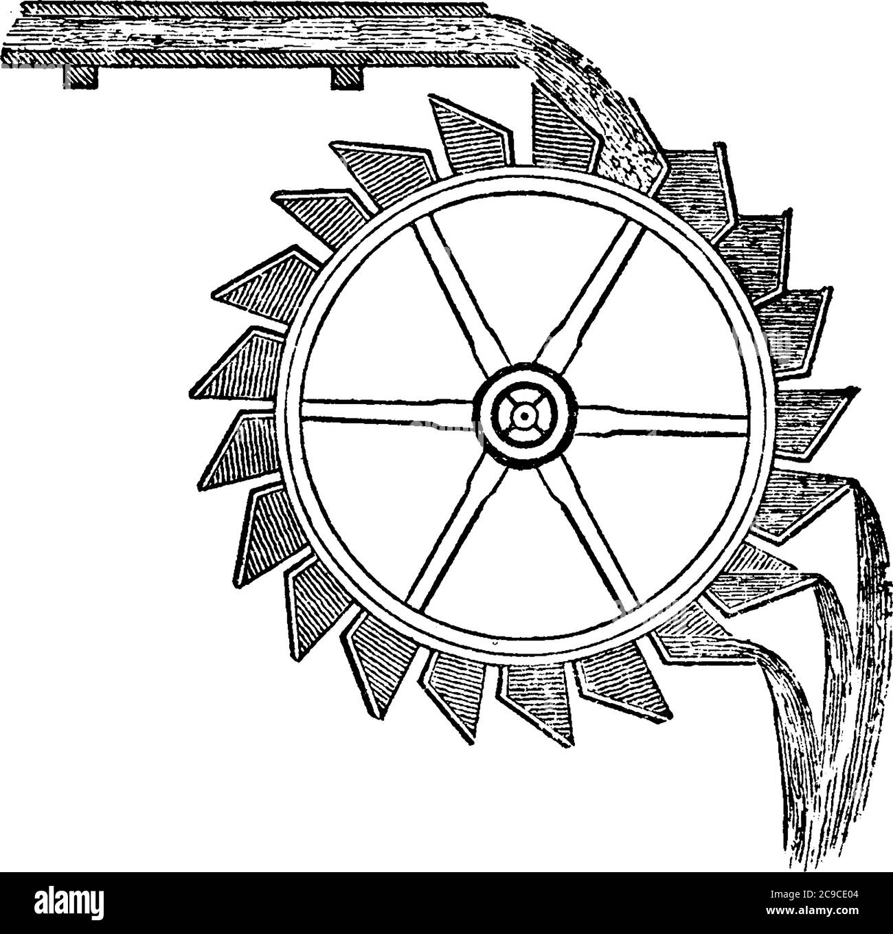
As water pours down over one side of the mounted wheel and turns it, the spinning of the wheel is converted to an up-and-down pumping motion by an eccentric arm attached to the assembly’s two-inch-thick main shaft. This “arm”, to be truthful, is not really an arm at all . . . but simply a spot one and a half inches off center on the face of a 15-inch gear salvaged from a local junkyard. The spot has been drilled and tapped to accept a threaded mounting pin for the lower end of a long white oak connecting rod.
As the water wheel’s main shaft rotates, then, the 15-inch gear attached to it also rotates smoothly. This causes the eccentric pin fastened to the face of the gear to revolve around and around in a three-inch arc. Which, in turn, causes the guided white oak connecting rod that rides the pin to pump up and down with a three-inch stroke.
The upper end of the connecting rod (think of it as the hand holding the handle of an old-fashioned “armstrong” water pump) is bolted to a cross-arm that runs across the top of a reservoir and is secured to a red cedar post on the other side so that it can hinge up and down. And in the middle of that cross-arm — just off center in favor of the water wheel — is attached a cylinder rod which runs down to a cylinder pump that is firmly bolted to the bottom of the reservoir.
And that’s all there is to the Wooding stream-run, spring-fed water system. Water from the spring 120 feet away runs a couple of feet downhill to fill the cement reservoir. At the same time, a great deal more water from the dam — also about 120 feet away but in a slightly different direction — flows through the flume and pours down over one side of the 6 1/2-foot water wheel, causing it to turn. And, as the wheel turns, the pump in the reservoir pumps . . . which forces the fresh spring water 100 feet uphill (through a line buried beneath the frost line) to a 500-gallon storage tank which stands near the blooding house. And, from that tank, the spring water is then gravity-fed to the house, stables, and swimming pool on the blooding property.
And there’s something rather nice about the whole arrangement. The “splash-splosh” of the water wheel is far more relaxing and natural than any huffing-puffing engine . . . and a lot less expensive to operate year in, year out than any quiet but increasingly costly electric motor. Every bit of technology used in the Wooding setup, of course, has been around a long, long time . . . and a lot of other farmsteads in the country could put a variation of the same idea into use right now.
Water wheels are generally perceived as being inefficient energy converters which belong to the past, with no role for the future. But as Gerald Müller, Klemens Kauppert and Rüdiger Mach explain, they can actually be efficient and cost-effective in low head micro hydro applications
IN EUROPE, a large number of low head micro hydro power sites (head = <5m, power = <100kW) exist. Water power was a prime power source during the industrial revolution and thousands of water mills were built at low head sites. Today however, the large majority of such hydro power sources is not exploited due to the lack of a cost-effective hydraulic power converter. Recently, a number of developments appear to have opened up the possibility to generate electricity economically at low head sites. These developments include the two oldest hydraulic machines, namely water wheels and the Archimedian screw - the latter working in reverse as a power source rather than as a pump.
Water wheels are today often considered to be relics from the beginning of the industrial revolution; romantic but inefficient hydraulic machines made of wood and belonging to the past. It is generally believed that turbines are much more efficient than water wheels and subsequently took over their role as hydraulic power converters. The statistics however show a different picture. In Bavaria - a German province with an area of 70,500km2 - there were 7554 operational water wheels counted as late as 1927, with power outputs ranging from 0.75 to 75kW. In the middle of the 19th century, a high stage of development was reached when Zuppinger designed the most modern and efficient water wheel. Engineers, manufacturers and mill owners must have regarded water wheels as commercially interesting power sources. During the 1940s however, virtually all water wheels seem to have disappeared.
Today, some companies in Germany (Bega, Hydrowatt) and the US (Water Wheel Factory) are again manufacturing water wheels for electricity generation. The performance characteristics of such wheels still appear to be largely unknown. Assessment of the available power potential, comparisons with other turbine types such as the Kaplan or the Ossberger (crossflow) turbine, and even the determination of optimum operating conditions for water wheels, relies on estimates.
"Modern" water wheels, ie water wheels built using scientific principles, are made of steel and employ only the potential energy of the water since in low head flows the potential energy exceeds the kinetic energy of the flow by far. These water wheels can be divided into three fundamental types:
Water wheels were, in the large majority of cases, used to drive machinery and reached efficiencies of 75-89%. This development seems to have subsequently been forgotten.
In Karlsruhe, Germany, a small non-profit research company (IFMW - Institut für Forschung und Medien im Wasserbau) has been set up which specialises in hydraulic engineering research, and in particular in the development and promotion of low head hydro power. Within the company, a very detailed literature and market review on water wheels was conducted in order to assess the suitability of water wheels for electric power production. Since only over and undershot wheels are currently built, the discussion will be limited to those two types.
The overshot wheel receives its feeding water at the top of the wheel, catches the water in buckets or "cells" and releases the water at the lowermost possible elevation. In order to make maximum use of the energy contained in the water, the cells are shaped so as to receive the water at its natural angle of fall and then to retain it as long as possible.
Some measurements of the performance characteristics of overshot wheels were conducted in 1928, as shown in the figure below. It was found that the efficiency of a water wheel reaches 85%.
The undershot wheel was developed for the utilisation of very low heads from 0.5-2m. Whereas in ancient times the kinetic energy of the flow was utilised with a paddle-type wheel, "modern" undershot wheels built after Zuppinger"s design employ the potential energy only. The figure below shows a Zuppinger wheel with the typical "backwards" inclined curved blades.
Wheel diameters range from 4-7m, with head differences from 0.5 to 1.5m. The blades are arranged in a way so as to avoid losses at the water entry, then gradually reduce the head of water in each cell and finally to discharge the water, again with a minimum of losses. The wheel blades are curved to allow for a gentle decrease of the water level from upstream to downstream, and to minimise losses at the downstream end. In an engineering textbook from 1939 it was stated that efficiencies of 76% can be guaranteed for properly designed undershot wheels.
Recently, the undershot wheel has also experienced a small renaissance. Hydrowatt has built and installed 15 Zuppinger wheels over the last nine years, with diameters ranging from 4-7.5m, and widths of 0.5-3m. Hydraulic heads utilised ranged from 1-2.2m, with typical flow rates of 1.5-3.1 m3/sec, giving power outputs from 4-45kW of electrical power. The overall efficiency (from hydraulic power available to electric power out) was estimated as ranging from 60 to 65%.
In the UK, many smaller streams were made navigable by building weirs, many of which still exist. Generally, the head differences were in the range between 1.2-1.8m. The undershot wheel may offer a possibility to produce electric power from such weir sites. The picture below shows a typical weir situation (Eel weir on the Lagan river in Northern Ireland) with a virtual water wheel inserted. The water wheel actually fits into a "natural" environment very well, indicating that a modern machine can become a visually attractive feature too.
The screw shown in the picture above was designed for a maximum flow rate of Qmax = 0.35 m3/sec. In experiments, it reached an efficiency of 70% for Q/Qmax = 0.4, and 80% for 0.6 < Q/Qmax < 1.0. The screw rotates at 53rpm, so that fewer gear ratios than for a comparable water wheel are required to achieve the speed necessary for electricity generation. To the author"s knowledge, six hydraulic screws have been installed already. Some design guidance for hydraulic screws, based on the design experience with screw pumps and generator experiments, is also available.
The economics of micro hydro converters are a function of variable boundary conditions such as electricity prices and so on. In Germany, overshot water wheels are currently built (including installation and grid connection) for 4360-4850 US$/kW. Undershot wheels cost 7760-9700 US$/kW, Archimedian screws approximately 8250-8730 US$/kW installed capacity. For comparison, low head Kaplan turbines cost 14500-15500 US$/kW. Although water wheels and the Archimedian screw have significant cost advantages over turbines, micro hydro installations are economical only if the owner uses the generated electricity at least partially, such as for a small business. Assuming 50% of self use, 6000 hours of operation per year at nominal capacity, a small business electricity price of 11 c/kWh and a price of 7.3 c/kWh for electricity fed into the grid, the following pay back periods apply:
The general perception amongst the public as well as many engineers is that water wheels are inefficient energy converters and belong to the past. Water wheels, and in particular the overshot variety, are however very efficient and cost-effective energy converters for low head micro hydro power applications. Today, the wider application of water wheels seems to suffer from a lack of information on water wheels, the lack of any design guidance and - possibly the most important aspect - the lack of actual data about the performance of such wheels.
Apparently, no performance data at all exists for undershot wheels, whereas some information is available on overshot wheels in old reports. IFMW Karlsruhe is currently conducting a detailed review and analysis of the experimental data available on overshot wheels with a view to application of such wheels for electricity generation.
The determination of performance characteristics for overshot wheels, and the publication of such data, will be the next task of the company, followed by a detailed evaluation of undershot wheels.
Ecological aspects are today a major issue in the design of hydro power installations. Both the water wheel and the Archimedian screw are considered to be very fish friendly because of the large compartments for the water and the slow speed, even for long fish like eel, thus giving them a considerable advantage over the fast rotating Kaplan turbines.
John Blake Campbell was born in Roanoke, Virginia, in 1890 and was theson of a Presbyterian minister. Growing up all around him was the movingpower of water and the numerous rural mills. This inspiration led him tostudy hydraulic engineering at Cornell University. During 1915-1916 he returnedto his mountain roots to study the old water-powered mills which survivednear his home in Virginia. In 1916-1917 he was an engineering salesman forthe Fitz Water Wheel Company of Hanover, Pennsylvania, a firm that specializedin small hydropower installations. He soon however began to lock heads withMr. John Samuel Fitz of the Fitz Water Wheel Company about how they constructedwith water wheels with its hundreds of drilled holes and rivets that heldthe pieces together. After his parting from Fitz, he served in the ArmyEngineers during 1917-1919. John Blake Campbell then moved to Philadelphiaand founded his own company in 1920. During this time he designed overshotwater wheels in welded steel, essentially applying modern production technologyto a relatively primitive device. He also worked on turbine installations,municipal water systems and flood control, but he came to specialize intraditional water wheels and was particularly interested in them as estheticelements in the landscape. Consequently, much of his work was for decorativepower plants for private estates or for historic restorations. Mr. Campbellsaid that he wanted to work for the people who had the most money and couldafford to pay him. His customers included Henry Ford, numerous Rockefellersand du Ponts, as well as the Hagley Museum and Batsto Furnace restorations.
In later years, after he closed his manufacturing company in 1962, Mr. Campbelltraveled the countryside and worked out of his car. He traveled around thecountryside working from one mill to another. At first John B. Campbellwould have on the average of 7 jobs a month, but as the years passed onthese numbers were reduced to perhaps only 3 jobs per month. When he wouldrun out of his own catalog to pass out to potential customers, Mr. Campbellwould apply his round orange Campbell Water Wheel stickers with its camellogo onto Fitz bulletins. In the later years of his life, he saw the worldonly through his pop bottle thick glasses repentingly saying at each millhe visited, "This is the finest example of a mill that I have everseen." It became true for a lot of mills that he would visit as potentialwork was taken out from under for this aging hydraulic engineer and millwright.If you read his catalog, it reads in the same manor that he spoke. I rememberhim driving his old car and wearing a dark heavy coat and hat, and thosewonderful glasses that could only see the world the way that Mr. Campbellsaw it. I remember his ad in the early issues of Old Mill News, and ourpaths crossed on more than one occasion. The little man with a big heart.
From 1926 to 1929 the Fitz Water Wheel Company and a former employee JohnB. Campbell began to construct this new mill. It is a replica of an oldmill and was constructed from plans drawn by John Blake Campbell. It wasbuilt near an old mill site built by David Howe circa. 1744. The mill wasbuilt to produce flour and meal for the inn and also serve as a touristattraction for visitors. Much of the interior wood was chestnut. Four freshwater quartz millstones, weighing a ton apiece, were shipped from La Fertesous Jouarre, France, at a total cost of $238.00, and an 18 foot diameterovershot water wheel was purchased from the Fitz Water Wheel Company, althougha wheel of Mr. Campbell"s own design soon replaced it. All in all, thismill was built to be, according to Campbell who said".. it was thefinest mill ever built."
You can"t tell the difference between a Fitz Water Wheel and a CampbellWater Wheel from a distance. You have to get close enough to see the raisedletters on the hubs to know if it is a Campbell or a Fitz Water Wheel.
Much of the product line of the J.B. Campbell Water Wheel Campany was similarto that of the Fitz Water Wheel Company. Possibly some of Campbell"s productswere subcontracted by the Fitz Water Wheel Company. Mr. Campbell seemedto stretch the limits of hydraulic engineering and try and make his waterwheels more efficient that the classic I-X-L Fitz Steel Overshoot WaterWheel.
Two 9 foot diameter by 8 foot wide Overshoot Water Wheels being deliveredto the Borough of Media, Pennsylvania, for pumping water at their MunicipalWater Works. The Wheels are installed side by side and drive one pump. Togetherwith the Borough Engineer, Mr. Carolus M. Broomall, we planned and installedthe complete equipment.
Overshoot Water Wheel 30 feet in diameter and 1 foot wide, planned andinstalled by the Campbell Water Wheel Company for Andora Nurseries, ChestnutHill, Philadelphia, Pennsylvania. The Wheel is operated by a 1 1/2 inchpipe of water. The Water Wheel pumps water to a 20,000 gallon reservoiron top of a hill 250 feet above the Wheel, and from this point is distributedto all parts of the Nursery. The Wheel is mounted on ball bearings, whichmake it operate very efficiently. The bearings have to be greased only twicea year.
Overshoot Water Wheel 30 feet in diameter by 10 inches wide, plannedand installed by the Campbell Water Wheel Company for the Estate of Mr.Louis R. Page, Conshohocken State Road, Bryn Mawr, Pennsylvania. For sevenyears this Wheel has been used to pump water, not only to Mr. Page"s Estatebut also to the Estates of his two sons, Mr. L. Rodman Page and Mr. EdwardC. Page which adjoin his Estate. The water to operate the Wheel is carriedto the top of the Wheel in a 4 inch pipe. The pump inside the house drawsits water from a Spring 12,00 feet away and forces it to a high tank onthe hill, from which it is distributed to the three Estates. The Wheel ismounted on ball bearings, which materially increases its efficiency.
Our Overshoot Water Wheel, 11 feet in diameter and 1 1/2 feet wide, atthe John C. Campbell Folk School, Brasston, North Carolina, solved the problemof pumping spring water to a high reservoir. A shaft further utilizes thatpower for a saw, lathe, and sander in the Wood-Working Shop.
Overshoot Water Wheel, 6 feet in diameter by 18 inches wide, which pumpswater for the Henry Prices, Mountain Home, Monroe County, Pennsylvania.Before the Water Wheel was installed, The Henry Prices had tried hydraulicrams and gasoline engines, which had caused them no end of trouble and expense,and many times left them without water. The Water Wheel has not failed themin ten years and has been the greatest pleasure and comfort to them.
Water Wheel Pump Plant supplying spring water to "Runnymede,"the Hunting Box of Mr. J. Stanley Reeve, Doe Run, Pennsylvania. A beautifulstream, flowing in front of the house, turns the Wheel, and the spring wateris supplied to the pump from four fine springs which were located for Mr.Reeve farther up the Valley on his Estate. On top of the hill above thehouse the Campbell Water Wheel Company constructed a 15,000 gallon concretereservoir. A continuous stream of fresh, pure water flows into the reservoir,and the overflow goes down the hill and back into the stream again.

The Laxey Wheel (also known as Lady Isabella) is built into the hillside above the village of Laxey in the Isle of Man. It is the largest surviving original working waterwheel in the world.
The wheel was built in 1854 to pump water from the Glen Mooar part of the Great Laxey Mines industrial complex. It was named "Lady Isabella" after the wife of Lieutenant Governor Charles Hope, who was the island"s governor at that time.
Water from the surrounding area – including a number of local springs and streams – is collected in a cistern, which is above the level of the top of the wheel. A closed pipe connects the cistern to the top of the wheel; thus the water flows up the tower as an inverted syphon. The water falls from the pipe into the buckets (formed from wooden slats on the circumference) and makes the wheel rotate in what is described as the "reverse" direction: it is a backshot wheel. The crank has a throw of 4 feet (1.2 m) and connects to a counterweight and to a very long rod. This rod runs along the rod viaduct to the pumping shaft 200m away where the 8 feet (2.4 m) stroke is converted by a T-rocker into a pumping action.
Most of the wheel and rod is made of wood; however, key mechanical parts are metal to provide tension and bearing surfaces. The rod has attached wheels at intervals to permit the stroke"s motion with minimal friction.
The triskelion on the front of the wheel is backwards. This happened by accident when transferring the image onto the wall; they forgot to reverse it, so it is actually a mirror image of the symbol of Mann.
The mine employed over 600 miners at its peak, producing lead, copper, silver and zinc, until it closed in 1929. In 1965 the Manx Government bought the wheel and site. The wheel was restored; in 1989, it was put under the control of Manx National Heritage.


 8613371530291