
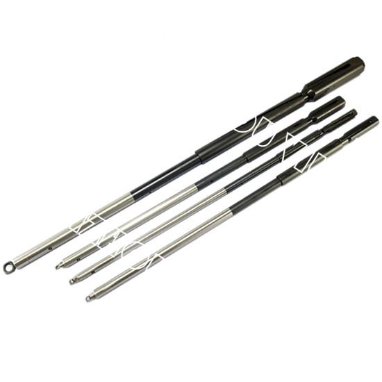
wireline overshot free sample

An OVERSHOT is attached to the end of a wireline and lowered into the outer tube. The Overshot then locks on to the Latch Head Assembly at the top of the core barrel.
The inner tube is then pulled to the surface with the core sample inside. Givens International offers an overshot for a spear point or quad latch head.
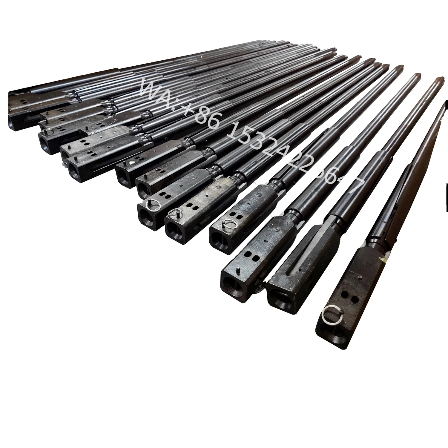
An overshot is lowered down on a wireline, latching onto the head of the core barrel, then the inner tube is pulled to the surface with the core sample intact.
[0001] The invention relates generally to a wireline overshot for connecting a wireline to an article within a borehole (or within a downhole tool in the borehole) and/or for retrieving an article from a borehole (or from a downhole tool disposed in the borehole).
[0002] A "wireline" overshot is used to connect a wireline to an article within a drill string. The article can be, but need not be limited to, a wireline coring inner barrel, a soft material sampling tool, a data gathering assembly, or an optional portion of a downhole drilling assembly. The wireline overshot may also be referred to as a fishing tool. In one example, the wireline overshot connects to the article within the drill string by latching over a spearhead coupled to the article. In another example, the wireline overshot may latch onto the article within the drill string by engaging a circular (or receiving) portion of the article. The wireline is commonly a flexible wire rope but may also be a solid wire (or "slickline"), synthetic braided rope, or small-diameter, flexible tubing. The wireline is typically lowered and raised by a winch.
[0003] In a typical core barrel retrieval operation, a wireline overshot is lowered on the end of a wireline down the drill string, where it latches onto an inner tube assembly of a core barrel disposed within the drill string. The wireline overshot is then pulled back to the surface with the attached inner tube assembly. At the drill floor, the inner tube assembly is held in a clamp or lowered onto the drill floor. An operator releases the wireline overshot from the inner tube assembly manually and sets the wireline overshot aside. In cases where the wireline overshot needs to be unlatched from the inner tube assembly while still within the drill string, the method of unlatching the wireline overshot is commonly one of free-falling a release sleeve onto the wireline
overshot, tensioning and releasing the wireline to ratchet a release pall, and repeated pulling or releasing of the wireline to shear a release pin. All of these operations require the wireline overshot to be reconfigured or rebuilt at the surface before it can function as an overshot again.
[0004] In a first aspect of the invention, an overshot comprises a sleeve, a coupling member having a latched state and an unlatched state disposed at a first end of the sleeve, and a load-responsive toggle mechanism for alternating the coupling member between the latched state and the unlatched state disposed at a second end of the sleeve.
[0005] In a second aspect of the invention, an overshot comprises an outer sleeve and a coupling member disposed a first end of the outer sleeve. A first rotator is disposed within the outer sleeve and configured to alternately engage and disengage from the coupling member, thereby toggling the coupling member between an unlatched state and a latched state. A second rotator is disposed within the outer sleeve and configured to selectively displace and rotate the first rotator in response to an applied load. A weight member is disposed at a second end of the outer sleeve for applying a load to the second rotator.
[0006] In a third aspect of the invention, a method of connecting or disconnecting a wireline from an article comprises providing an overshot comprising a sleeve, a coupling member having a latched state and an unlatched state disposed at a first end of the sleeve, and a load-responsive mechanism for alternating the coupling member between the latched state and the unlatched state disposed at a second end of the sleeve. The method includes coupling a wireline to the load-responsive mechanism, aligning the article with the coupling member, and selectively activating the load- responsive mechanism to alternate the coupling member between the latched state where it engages the article and the unlatched state where it disengages from the article.
[0012] FIG. 4 shows a weight jar assembly of the overshot of FIG. 1 applying a load to an upper rotator of the overshot of FIG. 1 while the overshot is in an unlatched state.
[0016] FIG. 8 shows a weight jar assembly of the overshot of FIG. 1 applying a load to an upper rotator of the overshot of FIG. 1 while the overshot is in the latched state.
[0017] FIG. 9 shows the keys of the lower rotator of the overshot of FIG. 1 released from the key slots of the key holder sleeve of the overshot of FIG. 1.
[0019] FIG. 11 shows the overshot of FIG. 1 after it has engaged an inner tube assembly within a drill string and has been retrieved to the surface with the inner tube assembly.
[0020] FIG. 1 is a cross-section of an overshot 10 for connecting a wireline to an article. The overshot 10 includes a cap 60 for connection to a wireline. A weight jar assembly 44 is coupled to the cap 60. The weight jar assembly 44 may include a weight bar 19 attached to the cap 60 by fasteners 21 , e.g., thread-and-set screws, and a jar stem 23 attached to the weight bar 19 by fasteners 25, e.g., thread-and-set screws. The jar stem 23 is received in a sleeve 22 and retained in the sleeve 22 by a jar bushing 27 mounted at the upper end of the sleeve 22. A toggle head 13 is received in the sleeve 22 and is positioned below the jar stem 23. A coupling member 14 is coupled to the toggle head 13 for engaging an article of interest. The article of interest may be any tool requiring a releasable connection with a wireline. For example, the article may be an inner tube assembly used to collect core samples from a subsurface formation, a soft material sampling tool, a data gathering assembly, and a component of a downhole drilling assembly. Connection and release of the overshot 10 from the article can be made at the surface, within a borehole, or within a tool disposed in the borehole.
[0022] Returning to FIG. 1 , the lifting dogs 18 are pivotally coupled to an axle 26 of the toggle head 13. A spring 28 is disposed between the upper ends 30 of the lifting dogs 18 to bias the upper ends 30 of the lifting dogs 18 away from each other. The pivot joint 33 between the lifting dogs 18 causes the lower ends 32 of the lifting dogs 18 (which include the hooks for engaging a part) to be biased in a reverse direction to the upper ends 30 of the lifting dogs 18. A toggle mechanism for moving the lifting dogs 18 between the latched and unlatched states includes a lower rotator 34. In the unlatched state, the upper ends 30 of the lifting dogs 18 are received within a bore of the lower rotator 34 so that the wall of the lower rotator 34 acts as a restraining ring around the upper ends 30 of the lifting dogs 18. In this unlatched state, the upper ends 30 of the lifting dogs 18 are forced towards each other against the force of the spring 28 and the lower ends 32 of the lifting dogs 18 are forced away from each other. The lower rotator 34 is axially movable along the toggle head 13 and sleeve 22. To transition the overshot 10 to a latched state, the lower rotator 34 is moved a sufficient distance in an upward direction to release the upper ends 30 of the lifting dogs 18 from the lower rotator 34. Once the upper ends 30 are released, the spring 28 would move the upper
[0023] The toggle mechanism includes an upper rotator 40 disposed about the shaft 24. The upper rotator 40 is held in place above the lower rotator 34 (and about the shaft 24) by a spring 42. The term "rotator," as used herein and above, means a part that can rotate or that can rotate another part. In one example, the upper rotator 40 is configured to rotate the lower rotator 34. The upper rotator 40 is slidable along the shaft 24 upon application of a load to the upper rotator 40 by the weight jar assembly 44. For the upper rotator 40 to be slidable, the load applied by the weight jar assembly 44 must be sufficient to overcome the biasing force of the spring 42 holding the upper rotator 40 in place. As will be further explained below, the load should also be sufficient to overcome the biasing force of the spring 38 holding up the lower rotator 34, or the biasing force of the spring 38 holding up the lower rotator 34 should be less than that of the spring 42 holding up the upper rotator 40. A wireline (not shown) coupled to the weight bar 19 through the cap 60 is used to control the position of the jar stem 23 (of the weight jar assembly 44) within the sleeve 22. The jar stem 23 is movable between an upper position limited by the jar bushing 27 (at the upper end of the sleeve 22) and a lower position limited by the upper rotator 40. When the weight jar assembly 44 rests on the upper rotator 40, it applies a load to the upper rotator 40. As will be explained below, this load assists in shifting the lifting dogs 18 between the latched and unlatched states. Contact is required between the jar stem 23 and the upper rotator 40 to allow the weight jar assembly 44 to apply a load to the upper rotator 40. Contact can be achieved in one of two ways. One way is by letting go of tension in the wireline (not shown) coupled to the weight bar 19 so that the jar stem 23 slides down the shaft 24 to contact the upper rotator 40. The other way is by moving the overshot 10 upwardly so that the upper rotator 40 slides up the shaft 24 to contact the jar stem 23. A jar bushing
12 latched into a core barrel 56. The overshot 10 is in an unlatched state, with the lifting dogs 18 slid down the spearhead 16 and held open by the shoulder 57 of the spearhead 16. This frees the lower rotator 34 to rotate without the friction that would be caused by the spring 38. In the example shown in FIG. 3, tension in the wireline has been relaxed, allowing the weight jar assembly 44 to rest on and apply a load to the upper rotator 40. Relative motion between the overshot 10 and the wireline (not shown) is used to bring the jar stem 23 of the weight jar assembly 44 in contact with the upper rotator 40. Relative motion can be achieved by releasing the weight jar assembly 44 from above,
e.g., through relaxation of tension in the wireline coupled to the weight jar assembly 44, or by moving the overshot 10 upwardly. The weight jar assembly 44 applies weight to the upper rotator 40 and, as shown in FIG. 4, causes the upper rotator 40 to slide down the key holder sleeve 46 and engage the lower rotator 34. As shown in FIG. 5, the upper rotator 40 pushes the lower rotator 34 down until the keys 54 (on the lower rotator 34) are positioned below the keys 48 (on the key holder sleeve 46). As previously explained, the load applied by the weight jar assembly (44 in FIG. 1 ) must be sufficient to overcome the force of the spring (42 in FIG. 1 ) holding up the upper rotator 40 and the force of the spring (38 in FIG. 1 ) holding up the lower rotator 34. The lower rotator 34 then rotates clockwise (looking down) as the tension of the spring (38 in FIG. 1 ) pushes the lower rotator 34 upwardly against the beveled surface 62 of the upper rotator 40. The keys 54 slide into the key slots 50 without the stop pins 52, as shown in FIG. 6. The lower rotator 34 moves upwardly as the keys 54 slide upwardly inside the key slots 50. As shown in FIG. 7, this causes the upper ends 30 of the lifting dogs 18 to be released from the lower rotator 34. The spring 28 moves the upper ends 30 of the lifting dogs 18 outwardly, which causes the lower ends 32 of the lifting dogs 18 to move inwardly and latch onto the spearhead 16. In the latched state, the weight jar assembly 44 is held again in tension to avoid exerting weight on the upper rotator 40, and the upper rotator 40 is held above the lower rotator 34 by the spring 42. The lower rotator 34 is held in place by the keyed connection described above and the force of the spring 38.
[0026] To release the lifting dogs 18 from the spearhead 16, the weight jar assembly 44 is again brought into contact with the upper rotator 40 to apply a load to the upper rotator 40, as shown in FIG. 8. As previously explained, the weight jar assembly 44 can either slide down to contact the upper rotator 40, or the overshot 10 can be moved upwardly to allow the upper rotator 40 to slide up and contact the weight jar assembly 44. The upper rotator 40, under the load of the weight jar assembly 44, slides down the key holder sleeve 46 to engage the lower rotator 38 and push the lower rotator 38 down so that, as shown in FIG. 9, the keys 54 are positioned below the keys 48. For this to happen, the load applied by the weight jar assembly 44 must be
[0027] The overshot 10 can be used to connect a wireline to an article, such as an oilfield tool, either at the surface or in a borehole. The overshot 10 can be disconnected from the article by the same action used in connecting the overshot 10 to the article, as described above. The overshot 10 can be used in any drilling or wireline operation. For illustration purposes, FIG. 10 shows the overshot 10 suspended at the end of a wireline 70 in preparation for lowering the overshot 10 into a drill string 72 containing a core barrel with an inner tube assembly. The drill string 72 is disposed in a borehole 73 drilled in a subsurface formation 75. FIG. 11 shows the overshot 10 after it has engaged the inner tube assembly 12 and been retrieved to the surface with the inner tube assembly 12. A handling arm 74 holds the inner tube assembly 12 while the overshot 10 is disengaged from the inner tube assembly 12 as described above.

That’s exactly what National EWP was looking for when it put the new Epiroc DiscovOre wireline coring system and Arrow 3S overshot to the test in a side-by-side field trial at a customer’s Arizona property. Both systems were run on the job’s Christensen CS14.
The site superintendent explains that a key focus area for almost all wireline core drilling is reducing “hit time,” or the time it takes for an overshot to lock onto the coring assembly after falling hundreds or thousands of feet through drilling mud. “Shortening the hit time when you’re coring 5- and 10-foot lengths can make a huge difference over a shift. When you can consistently shorten the tube-to-tube cycle, you get more feet drilled in a day.”
Greg Leavitt, Epiroc sales specialist in tooling exploration, visited the site to help with the timings. Leavitt says that while faster hit times were definitely the focus of comparison, safety is National EWP’s top priority. “It’s important not only to National, but their mining customers. Their customers only permit safe operators on their projects. When they choose National EWP, they know they’re guaranteed that. That’s why National is interested in the DiscovOre system and Arrow 3S overshot. They never stop looking for safety improvements.”
The National crew was completing the final hole of a five-hole survey in an especially problematic, highly fractured formation. Blockages frequently limited core lengths to just 5 feet or less. “Every extra minute waiting for the overshot to hit and lock onto the tube is multiplied by the number of trips out of the hole over each 12-hour shift,” Leavitt says. “It’s a significant amount of lost coring time.”
The system range covers all exploration tool sizes and works with common makes of exploration drill pipe, tubes and bits. Holes ranged from 300 to 2,100 feet with HO-size tooling set up for 10-foot-long, 2.4-inch-diameter triple-tube coring. The crew alternated every other sample between the DiscovOre system and their unmodified, traditional head and overshot system, as another of the system’s advantages is that it is compatible with exploration tooling the company already has.
The DiscovOre system design addresses several design weaknesses of older style wireline systems, according to the company. It completely eliminates the spearpoint, and there are no roll pins in the tube head to fail. The streamlined design decreases overall weight for greater ease and safety in handling. The Arrow 3S overshot locks into the coring assembly automatically and hits faster.
“The customer National is working for now, for instance, requires a three-fold redundancy in safety mechanisms.” One of those, Leavitt explains, is the helper’s ability to manually twist-lock the overshot in place. “What their customer likes about the DiscovOre system is that it has an automatic latch. It doesn’t need a twist lock. You don’t have to touch it, and that’s the ultimate in safety.”
Growth in the ‘50s fueled new technology, and in 1953, Longyear applied for a patent on the first wireline core retrieval system, the Q™ Wireline. Tom Shenosky, Epiroc product manager of Exploration Rock Drilling Tools, says many wireline tooling systems produced by various manufacturers over the years have, for the most part, simply continued the original system’s design based on spearhead, roll pins and open bearing assembly.
That changes with the DiscovOre. The overshot and tube head are key focus points for improving both efficiency and safety. The system has no spearhead and no roll pin in the head assembly, with sealed bearings and a sleek design, reducing its mass by about 10 pounds.
The DiscovOre and Arrow 3S design “flips” the locking system. Instead of a spearpoint that plunges into an overshot assembly, the Arrow 3S latching takes places within the head assembly. The company says the design isn’t just safer on the string. A common safety practice for other systems is to fold a spearpoint down when it is on the rack waiting for reuse. But spearpoint roll pins commonly jam up after they have been in use for some time. When handlers can no longer fold them to the side, they are left extended straight out from the body, presenting a risk of injury to workers moving around them.
The roll pin and the spearhead are the sole points of support, core after core, all shift long, day after day. That makes them critical wear points and common cause of premature failure. When they fail inside a hole, exploration drillers waste production time trying to fetch the tube out. Failing outside of the hole results in heavy tubes dangerously bouncing around a helper and driller in a confined work space. The company says DiscovOre eliminates the spearhead and the roll pins in the tube head altogether, providing not only safer, but more reliable and more efficient solution for wireline systems.

The Series 10 Sucker Rod Overshot is a small, rugged tool designed for engaging and retrieving sucker rods, couplings, and other items from inside tubing strings.
Series 20 Short Catch Sucker Rod Overshots are designed for conditions when sucker rods, couplings, and other portions of a fish are too short for retrieval with a standard overshot.
The Hydraulic Release Overshot was designed to aid in the recovery of a stuck fish in a horizontal drilling application where normal rotation for release is not obtainable.
The Series 150 Releasing and Circulating Overshot consists of three main external parts: a Top Sub, a Bowl, and a Guide. Internal catch and pack-off parts are determined by the diameter of the fish. Each assembly is designed for a maximum catch diameter.
A Series 160 Side Door Overshot is recommended when fishing for cable tools or conductor lines in cased holes. The side door overshot is run in on tubing or drill pipe.
The dependable Hydraulic Wireline Jar utilizes a hydraulic system that permits controlled jarring in measuring line or stranded wireline operations when electrical continuity below the jar is not required.


 8613371530291