
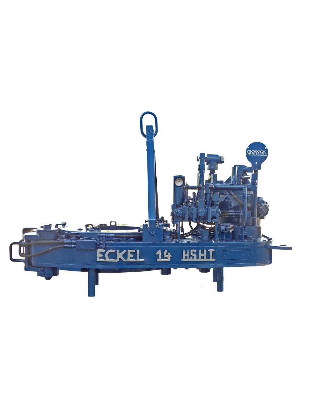
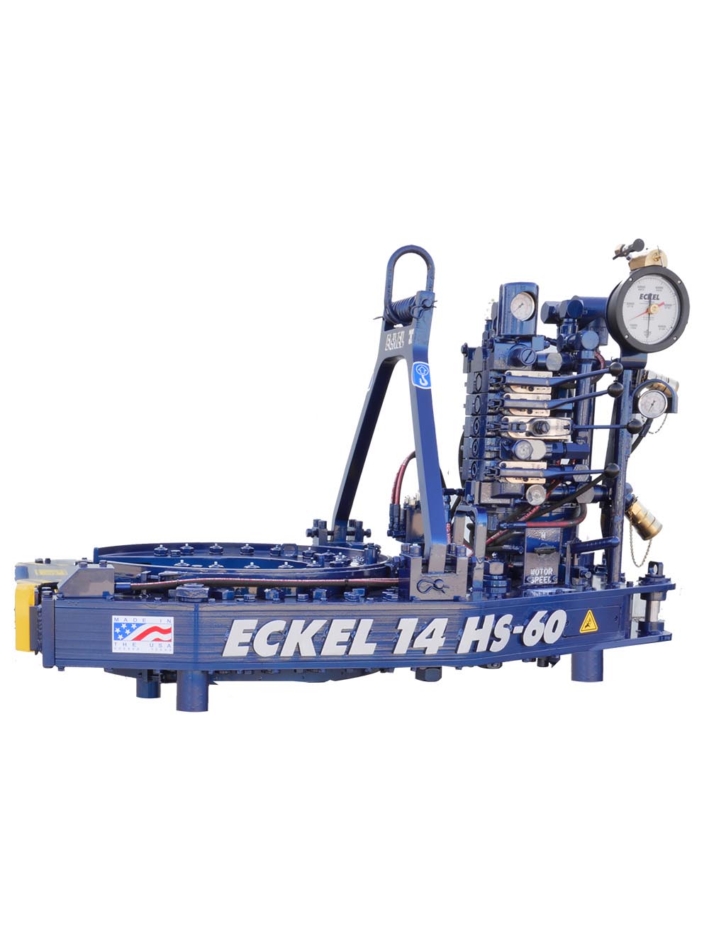
14 eckel power tong in stock
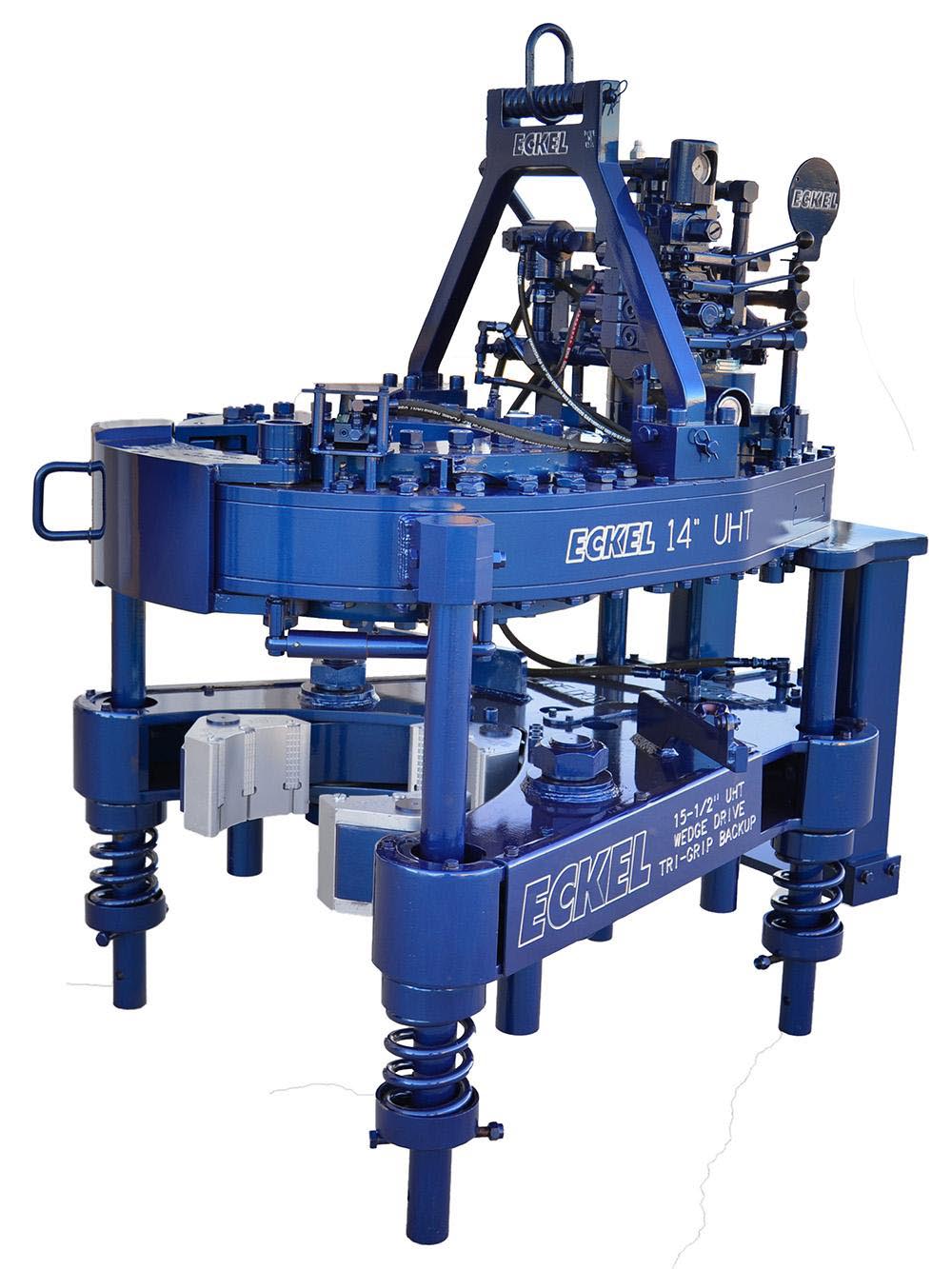
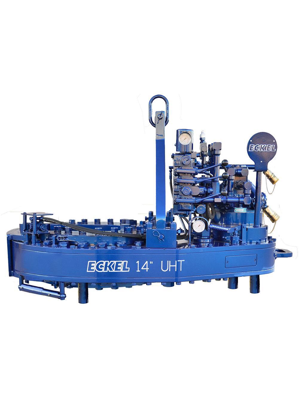
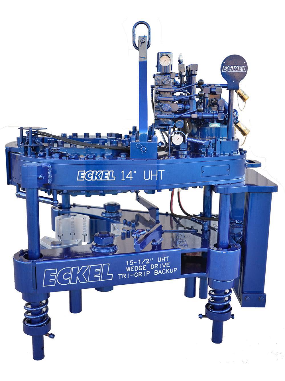
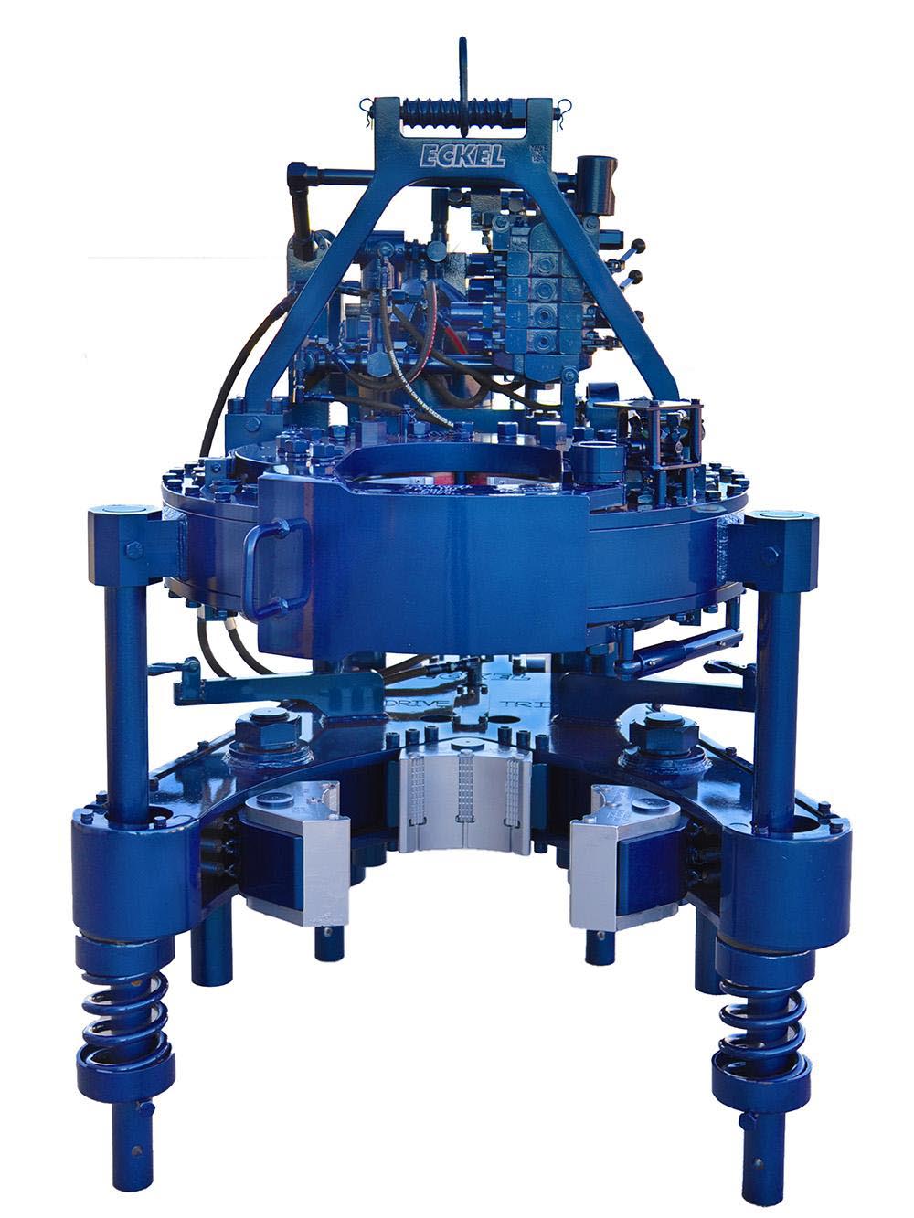
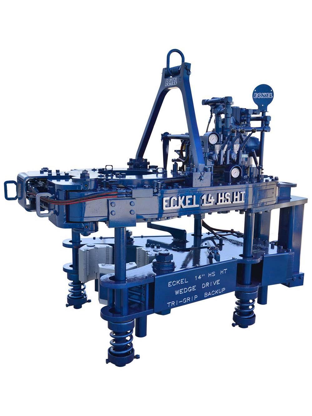
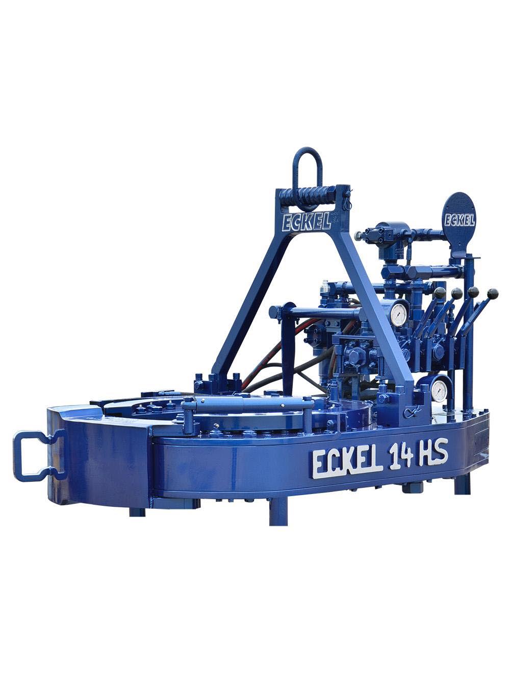
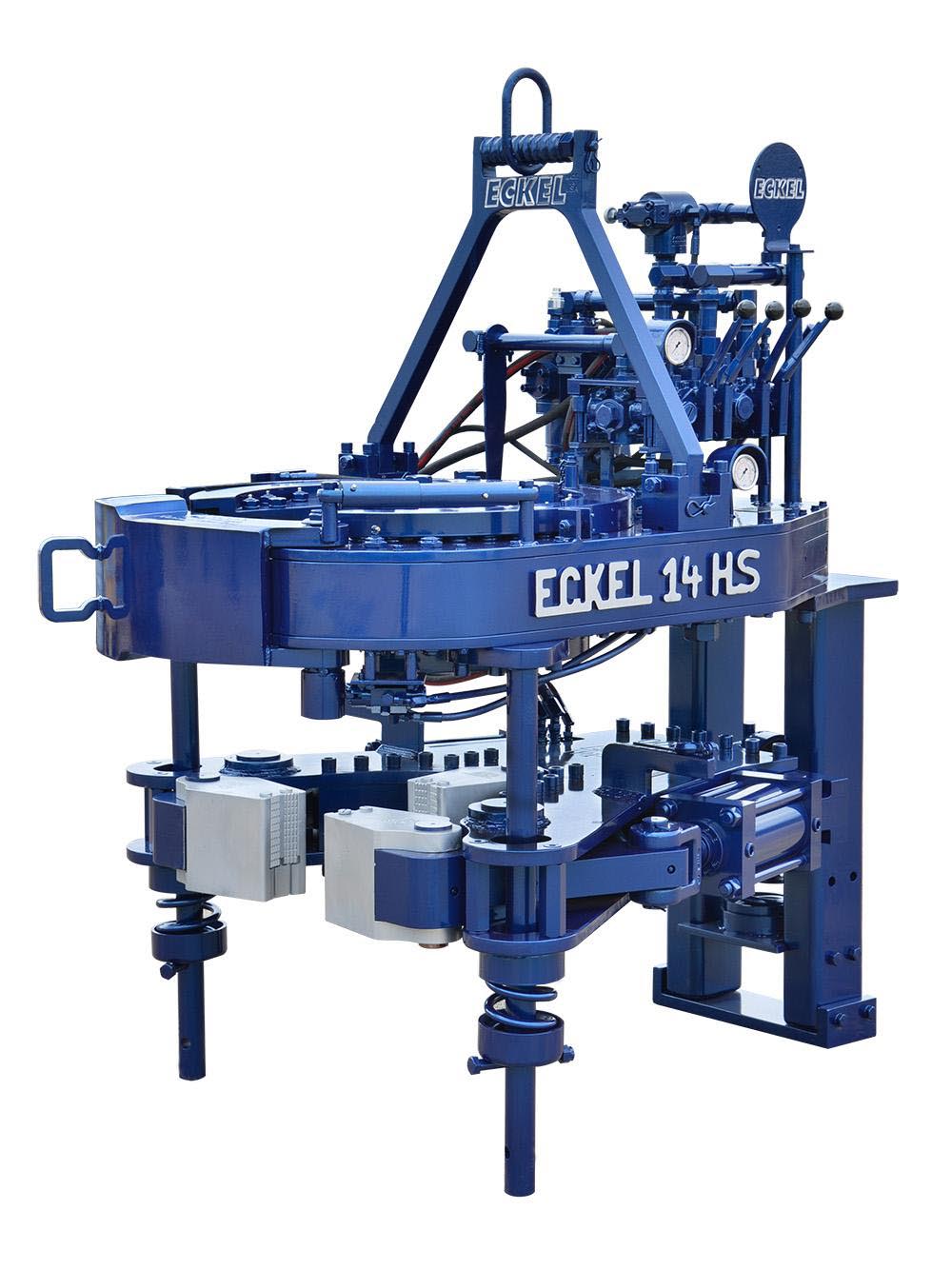
An excellent choice where applications demand the combination of size range and high torque output, the Eckel Model 14 UHT handles pipe from 4 inches to 14 inches. This tong features our new patented CASE STIFFENERS that enhances overall torque output. Upgraded in design and performance over the Model 14 HS, this tong can deliver 70,000 ft-lb of torque. Also, available with Wedge Drive Tri-Grip® backup, which handles pipe from 4 inches to 15.5 inches.
Our patented CASE STIFFENER technology enhances overall torque to provide consistent torque output. Having a high full 360° rotational torque and speed-shifting capability ensures the tong can makeup special torque-turn connections that require continuous rotation. Also, the CASE STIFFENER technology reduces stress and wear on the rotary gear teeth.
The WD Tri-Grip® Backup is a high performance no compromise backup that is suitable for make-up and break-out of the most resilient connections. The WD Tri-Grip® Backup features a three head design that encompasses the tubular that applies an evenly distributed gripping force. The backup is capable of handling tubular from 1.050 in. to 15.5 in. (26.67 - 393.7 mm). A constant radial load is applied when a single wedge drive to actuate the front two pivot heads with a third stationary head providing a reactionary force to provide superior gripping performance. Wedge Drive Tri-Grip® Backup has exceptional gripping capabilities with Rig Dies when running drill pipe or optional Eckel Wrap-Around True-Grit® dies or Pyramid Fine Tooth dies for making up other types of tubular.
The 14 HS HT Tri-Grip® Tong is used for making up and break out casing and risers. Capable of handling tubular from 4 in. to 14 in. (101.6 - 355.6 mm) in diameter with a maximum torque of 135,000 ft-lbs (183035.4) of torque capacity. A two-speed Hydra-Shift® motor coupled with a two-speed gear train provides (4) torque levels and (4) RPM speeds. The tong features a three-head - Tri-Grip® biting system design, which like the Tri-Grip® Backup, encompasses the tubular to apply an evenly distributed gripping force. The additional head in the tong reduces the risk of radial deformation, die penetration, marking, and wear of the tubular by 1/3 at extreme torques. The tong performs exceptional gripping capabilities with either Eckel True-Grit® dies or Pyramid Fine Tooth dies.
A new, improved tong door - The Eckel patented Radial Door with Hook Latch provides significantly more strength to the tong body. The latching mechanism is a straightforward design that is hydraulically operated to open and securely close the door with ease. When closed a positive force is applied to the tong body, which provides higher rotational torque.
The WD Tri-Grip® Backup is a high performance no compromise backup that is suitable for make-up and break-out of the most resilient connections. The WD Tri-Grip® Backup features a three head design that encompasses the tubular that applies an evenly distributed gripping force. The backup can handle tubular from 4 in. to 15 in. (101.6 � 381.0 mm). A constant radial load is applied when a single wedge drive to actuate the front two pivot heads with a third stationary head providing a reactionary force to provide superior gripping performance. Wedge Drive Tri-Grip® Backup has exceptional gripping capabilities with Rig Dies when running drill pipe or optional Eckel Wrap-Around True-Grit® dies or Pyramid Fine Tooth dies for making up other types of tubular.
Tongs - Power - BJ sucker rod tong adopts advanced sucker rod or tubing technology and has a compact structure, high reliability and is safe and convenient to operate.
Tongs - Power - New Carter Tool Co. Inc., CT93R Hydraulic powered tubing tong. Complete with 2-3/8" to 3-1/2" jaw assemblies, standard motor, torque gauge assembly, pressure relief valve... More Info
Tongs - Power - New Carter Tool Co., Inc. 5-1/2" CTSX Hydraulic Tubing Tong with heavy case and cover; complete with rigid hanger assy., suspension spring assy., front end control assy.,... More Info
Tongs - Power - New Carter Tool Co. Inc. M-Series power sucker rod tongs, complete with spring hanger assy., gate assy., front end control assy., pressure gauge assy., two 90 degree XH s... More Info
Tongs - Power - New Carter Tool Co., Inc. 4-1/2" RSX Hydraulic Tubing Tong with heavy case and cover; complete with rigid hanger assy., suspension spring assy., front end control assy., ... More Info
Tongs - Power - D D 58-93-2-R Power Tubing Tong is smaller, lighter, and faster than the Foster 5893R. The D D 58-93-2-R Tong is capable of gripping tubulars from 1 5/16" to 7" o.d. More Info
Tongs - Power - FARR TONG MODEL KT 14,000 RINEER GA37 MOTOR, LIFT VALVE ASSEMBLY TORQUE CAPACITY: 50,000 FT/LB SIZE RANGE 4 1.2-14 WITH SAFETY DOOR MOST SIZES OF FARR POWER TONGS ARE IN ... More Info
Tongs - Power - FARR TONG MODEL KT20,000 STAFFA 080 MOTOR, LIFT VALVE ASSEMBLY TORQUE CAPACITY: 50,000 FT/LB SIZE RANGE: 7-20 MOST SIZES OF FARR POWER TONGS ARE IN HOUSTON, IN STOCK READ... More Info
Tongs - Power - FARR MODEL KT5500 HYDRAULIC TUBING TONG C/W 2 SPEED RINEER MOTOR, SIZE RANGE: 2-3/8 IN. - 5-1/2 IN. OD, TORQUE RTED: 18,700 FT/LB C/W SAFETY DOOR MOST SIZES OF FARR POWER... More Info
Tongs - Power - FARR TONG MODEL KT5500 TORQUE CAPACITY: 18000 FT/LB SIZE RANGE: 2 1/16-5 1/2 OD WITH SAFETY DOOR MOST SIZES OF FARR POWER TONGS ARE IN HOUSTON, IN STOCK READY FOR IMMEDIA... More Info
Tongs - Power - FARR TONG MODEL KT5500 5 1/2 IN. TONG TORQUE CAPACITY: 18,000 FT/LB SIZE RANGE: 2 1/16-5 1/2 IN. OD, RINEER 15-13 MOTOR, HIGH TORQUE CLINCHER BACKUP TRIPLE VALVE ASSEMBLY... More Info
Tongs - Power - FARR TONG MODEL KT7585 TORQUE CAPACITY: 25000 FT/LB SIZE RANGE: 2 1/16-8 5/8 OD WITH SAFETY DOOR MOST SIZES OF FARR POWER TONGS ARE IN HOUSTON, IN STOCK READY FOR IMMEDIA... More Info
Tongs - Power - FARR TONG MODEL KT7585 8 5/8 IN. TONG TORQUE CAPACITY 25,000 FT/LB SIZE RANGE: 2 1/16-8 5/8 IN. OD, RINEER 15-15 MOTOR CLINCHER BACKUP, TRIPLE VALVE MOST SIZES OF FARR PO... More Info
Tongs - Power - FARR TONG MODEL LW9625 TORQUE CAPACITY 12000 FT/LB SIZE RANGE 2 7/8 -9 5/8 OD WITH SAFETY DOOR MOST SIZES OF FARR POWER TONGS ARE IN HOUSTON, IN STOCK READY FOR IMMEDIATE... More Info
Tongs - Power - Farrs newest tubular connection tool offers a significantly reduced rig footprint, while continuing to deliver power & uncompromising reliability. The simple design drast... More Info
Tongs - Power - Farr Canada"s newest tubular connection tool offers a significantly reduced rig footprint, while continuing to deliver power and uncompromising reliability. The simple de... More Info

We are committed to delivering innovative designs and high performance powers tongs for the oil and gas industry. With 90% of all tong components manufactured and heat treated in-house, you are assured reliability and confidence on your next job with an Eckel tong!
The 14-100 hydraulic power tong provides 100,000 ft-lb (135,600 N∙m) of torque capacity for running and pulling 7- to 14-in. casing. The tong has a unique gated rotary, a free-floating backup, and a hydraulic door interlock.
Our 14-50 high-torque casing tong provides 50,000 ft-lb (67,790 N∙m) of torque capacity for running and pulling 6 5/8- to 14-in. casing. The tong has a unique gated rotary, a free floating backup, and a hydraulic door interlock.
The 16-25 hydraulic casing tong provides 25,000 ft-lb (33,900 N∙m) of torque capacity for running and pulling 6 5/8- to 16-in. casing. The tong features a unique gated rotary and as many as seven contact points that create a positive grip without damaging the casing.
Rigged up without rig modifications, our 21-300 riser tong is the only tong capable of producing 300,000 ft-lb (406,746 N∙m) of continuous rotational torque in both makeup and breakout mode. The power it achieves in a compact size compares with a conventional 24-in. casing tong.
The 24-50 high-torque casing tong provides 50,000 ft-lb (67,790 N∙m) of torque capacity for running and pulling 10 3/4- to 24-in. casing. The tong features a unique gated rotary, a free-floating backup, and a hydraulic door interlock.
The 30-100 high-torque casing tong provides 100,000 ft-lb (135,600 N∙m) of torque capacity for running and pulling 16- to 30-in. casing. The tong features a unique gated rotary, a free-floating backup, and a hydraulic door interlock.
The 5.5-15 hydraulic tubing tong provides 15,000 ft-lb (20,340 N∙m) of torque capability for makeup and breakout of 1.66- to 5.5-in. tubing and premium or standard connections on corrosion‑resistant alloy tubulars. The tong features an ergonomic, lightweight design with a free-floating hydraulic backup.
The 7.6-30 hydraulic tubing tong provides 30,000 ft-lb (40,670 N∙m) of torque capability for makeup and breakout of 2 3/8- to 7 5/8-in. tubing and premium or standard connections on corrosion‑resistant alloy tubulars. The tong features an ergonomic, lightweight design with a free-floating hydraulic backup.
Our SpeedTork 8.0-70 tong provides torques up to 70,000 ft-lb (94,900 N∙m) and 360° rotation in makeup and breakout operations. It can torque drillpipe connections, drillstring components, drilling tools, packers, couplings, and valves.
We’re thrilled to announce that two of our powerful Eckel 5½ Hydra-Shift® VS Casing Tongs shipped to North Africa! It has up to 22,000 ft-lb of max torque, a two-speed Hydra-Shift motor, a two-speed transmission, and Tri-Grip® tension backup. Tension backups, unlike compression, have identical handle lengths as the tong. This allows the torque gauge assembly to be calibrated for torque readings in both tong and tong & backup configurations. Invest in the best for your next job, and let the Eckel 5½ Hydra-Shift® VS power your success!
The 9-5/8” power tong with Rineer GA15-13 two-speed hydraulic motor, motor valve, lift cylinder valve, rigid sling, FARR® hydraulic backup, configured for compression load cell.
Power tongs are an essential tool in the drilling industry and are used to make up, break out, apply torque and to grip the tubular components. We are distributors for both Starr Power Tongs and McCoy Global hydraulic power tongs in multiple sizes and torque ranges from high torque to low torque that can be used to run both casing, drill pipe and tubing. When determining which power tong is best for your project, you will want to select the power tong that best fits your tubular size ranges and torque required.
All of our power tongs are available with either the McCoy\\\\\\\\\\\\\\\"s patented WinCatt data acquisition software recently updated to the MTT systems or AllTorque\\\\\\\\\\\\\\\"s computer monitoring system for all the torque and turn control system needed in today\\\\\\\\\\\\\\\"s market for the making of tubular connections. Discover our wide selection of McCoy and Starr casing tongs, tubing tongs and power tongs for sale below!
Established in 1958, Eckel is globally recognized as the leading manufacturer of hydraulic power tongs and hydraulic power units for the world’s oil and gas industries. We offer a full line of hydraulically operated drill pipe tongs, casing tongs, tubing tongs, hydraulic backups, hydraulic power units, and tong positioning equipment. Eckel delivers a comprehensive range of tongs from 2-1/16 through 36 in. for the most demanding onshore and offshore environments. Eckel Tri-Grip® backup is an industry standard for reliable make-up and break-out of tubular connections. Eckel’s cutting-edge designs, quality, and rugged durability have won us a world-wide reputation of a first-class product that insures years of trouble free service.
From our main manufacturing facilities in Odessa, Texas, USA (ISO 9001:2008 certified) essentially every part is designed and manufactured. The facility encompasses 140,663 square feet and houses the latest in design tools and numerically controlled machines and heat treating ovens.
Eckel high-performance tongs operate in some of the toughest operating environments around the world performing drill pipe, casing and work-over activities on onshore and offshore locations. Eckel is highly involved in drilling, well servicing, and work-over operations.
We offer a full range of high quality casing and tubing, drill pipe tongs for use in all types of oil and gas drilling, well completion and well servicing activities. Our tongs have been engineered for the high operational torques today’s that premium connections require. Eckel tongs continue to advance the technology of tool service and setting industry standards.
Our renowned free floating Tri-Grip® hydraulic backup provides unparalleled backup performance and is one of the industry’s closest tong mounting backups that minimize pipe bending. The backup utilizes three biting surfaces to insure a secure grip on the tubular to prevent tubular rotation.
Our remotely operated tongs provides a mean to control the tong for make-up and break-out operations. The tong is based upon the standard tong and backup configuration with the exception of hydraulic cylinders on the unit for remote control of the operations of the tong and backup. The functions include the tong door, backing pin, mechanical gear shift, power tong rotation, motor speed and backup gripping. Totally hydraulic with no electrical or electronic devices.
Eckel’s standard diesel or electric power packages at 65 GPM and 2,500 psi (246 LPM / 172 bar) are widely recognized for dependability and long, trouble-free service. Eckel will customize hydraulic power systems in the shortest possible time to meet “nonstandard” requirements for space, fluid flow, auxiliary power, and portability. Diesel driven units are optionally supplied with automatic shutdown systems to prevent engine run away when explosive gases are present. Additional shut downs include engine oil temperature, oil pressure, and fan belt breakage. All controls are either air, mechanical or electrical.
Eckel Manufacturing is committed to maintaining its position as an industry leader of the manufacturing of precision engineered specialty oil field equipment. It is our policy to provide our products at the highest quality that meets our customer’s requirements and demands.
I am chairman of the board, president and chief executive officer of Eckel International, the largest global providers of innovative and high performance hydraulic power tongs for the oil and gas industry. I am a second-generation family member involved in manufacturing of tongs. In 1993, as Eckel’s president, I launched an initiative to further reach out to Russia’s oil & gas needs. Today, I am directly responsible for the overall operations of the company, sales, and new market initiatives.
Since 1958 Eckel has been supplying power tongs to the worlds O&G industries– but how long have you been doing business in Russia and what specific solutions do you offer to the region?
Eckel has been conducting business in Russia since the 1978. In 1993, Eckel established an ongoing presence in Russia with CETCO as our local business partner. CETCO further extended our business across Russia & CIS as our local agent. We have observed strength in the Russia and CIS market, with solutions for drill pipe and casing operations.
Eckel specializes in the development of hydraulic power tongs for make-up and break-out of tubulars, with over 60 years of tubular connection experience. Our industry leading technology advancements are in some respects, a reflection on the industry requirements and their needs. Eckel has been in the process of designing tongs that required very high torques, advanced safety features, and automation.
Eckel in-house heating provides quality tempered steel while observing strict industry standards. This process assures high quality and rugged durable parts within Eckel power tongs. Eckel has won a world-wide reputation of providing first-class products that deliver years of trouble free service. Our tongs have operated trouble free in the harsh cold conditions of Western and Eastern Siberia and in the Far Northern Regions. Eckel’s hydraulic power units have a proven track record in some of the harshest surroundings in Russia such as the extreme hot and cold conditions of Russian and offshore environments.
Eckel has provided more than 500 Hydraulic Power Tongs to oil and gas companies and drilling contractors in Russia. In Russia, as well as in many other countries, the use of Corrosion Resistant Alloys (CRA) chrome tubulars are becoming more popular. Eckel is an industry leader in this specialized field tubular connections offering a line CHROMEBOSS® tongs along with Eckel Non-Marking True Grit® dies. True Grit® Dies utilize Tungsten Carbide grit coating which provides many more points of contact on the surface of the tubular than standard Pyramid Fine Tooth dies provide. Penetration depth less than half the depth that is permissible by the American Petroleum Institute (API). Eckel’s True Grit® dies use a dense Tungsten Carbide coating that is a metal like substance which does not flake or sheer off the face of the die. Operational on-site tests have shown that the life time of Eckel True Grit® wrap-around dies is three times longer than competing abrasive powder coated dies. The above equipment and components have been working in Russia several years and proved its advantages.
The hydraulic power tong market is very competitive in Russia, with both local and international suppliers competing for business. Why should a drilling contractor or operator consider using Eckel equipment?
Eckel has over 60 years of experience in this area, and is known for quality and reliability. Many of these tong manufacturers use the old Foster and Hillman Kelly that are 30-year-old designs. Eckel is at the forefront of this industry designing tongs that can handle today’s premium high torque connections. Our tong designs evolved to incorporate additional safety features, automation, and performance. Our new 7.25 HSHT-80 Drill Pipe / Casing and 9-7/8 HS-60 Casing tongs incorporates many of these features.
Eckel has been the leader in development of tubular gripping such as the development of larger wrap-around type dies for many of its tong models. Depending on the application, Eckel offers a coarse tooth, pyramid fine tooth, and our proprietary True Grit dies. Dies are available as rig die style and for thinner wall tubulars where point loading is a concern we offer wrap-around dies. All Eckel equipment is produced at our Odessa, Texas USA manufacturing facilities (ISO 9001:2008 certified) that encompasses 140,663 square feet (13068 square meters) ensures the highest quality.
Eckel equipment is popular world-wide as having shipped to over 100 countries. Eckel is best known for its value in reducing costs, safer tubular connection, reduced maintenance, and mitigated downtime.
Coralina Engineering and Capital Equipment and Trading Corporation (CETCO) has operations in Azerbaijan, and their specialists are intensely involved in this territory. CETCO specialist are successfully making inroads in the Azerbaijan territory offering Eckel power tongs and power units. Additionally, CETCO provides training, classes, assistance, and local experience in all practical aspects of tong operation and maintenance. CETCO is very optimistic for doing business in Kazakhstan region. We are actively working in this region at improving our relationships with existing and new customers.
Eckel continues to improve tong designs, reliability, functionality, and reduce operational costs to comply with today’s oil and gas industry requirements, and anticipate tomorrows industry requirement. A few examples are:
• One of the latest design of a new backup with Wedge Drive Type Tri-Grip which is used on the most of tong models. The WD Tri-Grip is a high-performance backup with no compromises that is available for specific applications. The Wedge Drive Tri-Grip handles the most demanding torques that larger casing and drill pipes demand.
• A new 7.25 HS HT-80 tong, that was introduced in the last half of 2016 for drill pipes and high torque casing pipes. We believe the 7.25 HS HT-80 tong is an extremely needed product for the Russian market. We anticipate the specifications of the tong will be of great interest and welcome surprise for our customers.
• In 2017, Eckel will release a couple of new product designs. The new 9-7/8 HS-60 Casing Tong available the 1st Quarter of 2017 offers efficient and reliable high rotational performance for torque turn jobs. With these high torque ratings, the 9-7/8 HS-60 Casing Tong is capable of properly handling all premium grade tubulars within its size range.
Available in the 2nd Quarter of 2017, a new tong positioner “Tong Handler” that is permanently mounted within the rig which provides a cost effective, safer, and reduced labor-intensive method of maneuvering tongs to the rotary table area on the rig floor.
Russian is a very large and great country with lots of attention dedicated to the oil and gas industries onshore and offshore. Today’s challenge is to have equipment that meets the needs and requirements of oil and gas companies and drilling contractors. Since our first tong delivery in 1978 and now with the assistance of Capital Equipment and Trading Corporation and Coralina Engineering, we have developed a good relationship with many Russian customers and a growing list of new customers. Oil production is not so easy however; we believe that we can solve the most difficult problems facing the oil and gas industries. I have enjoyed visiting Russia many times for work and pleasure.
1-1 FunctionalElementsofthe20-lnchTong ......1 t-z Hydraulic Drive System Schemat¡c D¡agram .... 2 1-3 ClutchandSpeedShiftDetails ..... 3 14 HeadB¡t¡ngAction.Makeup .......4 1-5 Head Cage Plate and Rotary Gear Deta¡ls ..... 4 1-6 BrakeBandsandsafetyDoor ,,....5 z-l TongDimensions .,.,... 7 ¿-¿ TorqueGaugelnstallation .....,.., I 2-3 Tonglnstallation .... 8 24 Hydraulicconnect¡ons .,... 9 3-1 OperatingControlsandGauges .,....11 4-1 TonglnspectionPo¡nts ..... "13 4-2 TongGreasePoints ,,,..... 14 4-3 TongAdlustmentPoints ...16 o-l Eckel Model 20 Casing Tong, Top Assembly (Exploded View) 21 o-z Clutch Assembly (Exploded Viewl 24 t"-J Pinion Assembly (Exploded View) 24 6-4 Pinion ldler Assembly (Exploded View) 25 6-5 Rotary ldler Assembly (Exploded Viewl . 26 6€ Tong Suspension Components, Simplified lllustration 27 6-7 Microswitch Assemblv 2A
1-1 SpecificationsEckel2O"CasingTong ........ 6 3-1 Operatingcontrolsandcauges ......11 4-1 RecommendedLubricants . .. r+ 5-1 TroubleshootingChart ....17 6-1 PartsList,EckelModel20CasingTong . ......20 o-¿ PartsList,CfutchAsembly ..,....23 6-3 PartsList,PinionAssembly ..,....23 6-4 Parts List, Pinion ldler Assembly . . . . 25 6-5 Parts List. Rotary ldler Assembly . , . . 26 6-6 TongSuspensionComponents ,,,.,. 27 o-t PartsList,MicroswitchAssembly ,,.,24 Copyright, 1979, by Eckel Mfg. Co. Inc. All Rights ReservedFirst Reprint 9/80 SECTION 1
This manual describes the function, operation The Model 20 Power Casing Tong, Figure 1-.1,and maintenance of the Eckel Model 20 Hydraulrc handles casing sizes as small as B-5/B inches and asPower Casing Tong. This section provides a func- large as 20 inches in diameter. The open-throattional description, system specif ications, and a de- design, combined with high-speed operation,scription of options and accessories available. Sec- assures both ease and speed in casing handling,tions 2 through 5 present the operatrng and main- A safety door on the open throat helps insuretenance aspects of the tong and Section 6 provides against accidents. The following paragraphs de-a fully illustrated parts list w¡th spare recommen- scribe the functions of the tong during casingdatrons. makeup or breakout operations.
Fígure l-1. Functíonal Elements of the 2?-lnch TongFUNCTIONAL DESCR IPTION nf the nncratinn nrcsst tre at fhe tono rv, tY if desired. I
Most users set this valve for maximum oressure so Operat ing f rom a hyd rau lic power un it, the that full pressure f rom the power unit is applied topower casing tong provides a maximum torque of the motor; however, you may set the valve for35,000 ft-lbs. The heart of the unit is a head-clos- lower pressures if desired. The maximum pressureing system which forces the heads together and ro- available, of course, depends upon the power un¡t.tates them by means of a cam-type rotary gear. Eckel Manufacturing Company recommends aThe rotary gear is driven by a two-speed gear train power unit that will deliver 3000 PSI pressure;powered from a piston-type hydraulic motor. however, a power unit capable of delivering 2500 PSI at 30 GPM or 1.000 PSI at 65 GPM is neces- In operation, the tong is suspended over the sary to maintain maximum speed and torque.drtll hole on a chain bridle. A snubbing line re-strains the tong from moving around the pipe as A hydraulic motor is mounted on the tong topfnrñr ro ic annliod plate through a motor adapter, and the other hy- draulic plumbing components are also mounted on HYDRAULIC DRIVE SYSTEM. Fisure 1-2 the tong top plate.is a hydraulic schematic of the drive system, Hy-draulic pressure from a separate power unit is GEAR TRAIN AND CLUTCH FUNCTION. Closure and rotation of the pipe-gripping heads are accomplished by means of a large rotary gear hav- r-rl4" couPLrNG REV ERSIBLE ing its inner diameter formed into a double cam MOTOR surface. The rotary gear rides on a double ring of Ylv¡ cam-follower rollers. A cutout on one side of the pR essu Re I rotary gear accepts the vertical pipe being worked. REL¡EF This topic explains how mechanical power is trans- VALVE mitted from the hvdraulic motor to turn the ro- PR ESSU R E tary gear in either direction.
I Gear Train Elements. The gear train, Figure I 1-3, comprises the clutch assembly, pinion assem- I bly, two pinion idlers, two rotary idlers and the .orlt,*o rotary gear. The selected high- or low-speed clutch gear engages the corresponding high- or low-speed pinion gear, and the pinion output gear drives the CONTROL VALVE two pinion idlers which drive the two rotary idlers. In driving the rotary gear, two rotary idler gears are necessary to bridge throat cutout gap. Figure l-2. Hydraulic Drive System Schematíc Diagram Clutch and Speed Shift. The clutch assembly (F igure 1 3) provides h igh- or low-speed opera-applied through screw-type hose connectors hav- tion, allowing faster operation when high torqueing built-in check valves. To prevent cross-connec- is not required. When higher torque is needed,tion of the hoses, the pressure hose from the power the low-speed gear permrts the operator to slowunit is designed to mate with a "l-inch connector the speed down and increase the torque,and the return hose mates with a 1-114 inch con-nector. Connection of the hoses opens the check The operator shifts the speed by raising orvalves to provide hydraulic pressure to the tong. lowering a shifting lever on top of the tong. As shown in the illustration, lifting the shift lever lifts The tong control lever acts as a throttle valve the shifting yoke, which lifts the shifting collar. Infor the unit. Pushing the lever applies pressure to this position, the shifting collar mechanicallydrive the motor in a forward direction (for make- couples the clutch shaft with the h igh-speed clutchup operation) and pulling the lever applies pressure gear. Lowering the shifting lever lowers the shiftingin a reverse d irection (for breakout). While the yoke which lowers the shifting collar, therebylever is in a neutral position, f luid circulates f reely mechanically coupling the clutch shaft with thethrough the valve and back to the return line. low-speed clutch gear. Then the selected clutch gear drives the corresponding pinion gear as pre- An adjustable relief valve permits adjustment viously described. An adjustable spring detent on
the shifting shaft holds the yoke and shifting lever During breakout operations, the backup pinin the selected position until the operator moves is placed in the breakout position so that the headsthe lever once again. bite in the reverse direction (see Backing the Heads for Breakout Operation). Then the operator pulls the tong control lever to cause the heads to bite HEAD OPERATIONS. The heads are enclosed and breakout the pipe. Finally, he pushes the leverwithin the rotary gear by the top and bottom cage forward to release the heads and back them off theplates. The heads are closed, rotated and opened pipe.by the combined actions of the rotary gear, brakebands and backing pin. As illustrated in Figure 1-4, the head-biting action is a function of the rotary gear inner surface Rotary Gear/Head Functions. During makeup cam design. When the rotary gear begins to rotate,operations, the pipe to be turned is first enclosed the heaC rollers roll uo onto the cam surface andin the tong, and the throat safety door is closed. force the heads inward from the oivot points untilThen, with the backing pin in the makeup position the heads bite the pipe. Further rotation then turns(as described later) the operator pushes the head the pipe to makeup (or breakout) the joint.control lever forward to cause the heads to biteand rotate the pipe. To release the heads and back Rotary Gear and Head Cage Rotation. Figureoff from the pipe, the operator pulls the tong con- 1-5 illustrates the cam follower rollers that permittrol lever outward. the semi-independent rotation of the cage plates bottom cage plate also rotates on a roller track identically with the top cage plate. This plate is bolted to the top cage plate to enclose the heads. The heads are pivoted from the top and bottom cage plates to bite or release as brought about by the cam action of the rotary gear on the head ro | | ers.
CAM FOLLOWER ROLLER (TORRINGTON } CAM FOLLOWER BOLT IECKEL)
CAM FOLLOWER NUT AND WASHER (EcKEL) BACK CAGE TOP TONG PLATE PLATE BOLT
BOTTOM CAGE PLATE BACKING LUG ROTARY IDLER BOTTOM TONG PLATE ROTARY qAM GEAR FOLLOWER ROLLER (EcKELl
Figure l-5. Head Cage Plate and Rotary Gear Details design permits ease of operation by permitting BACKING PIN entry of vertical pipe that projects above the level ROTARY of the tong. For safety purposes it is necessary that GEAR the throat opening be closed during operation to . CAM prevent personnel injuries or damage to the equip- SURFACE ment. A double safety door (Figure 1-6) serves both to close off the front during operation and to HEAD provide an extra margin of support for the housing ROLLER du ring h igh-torque operation.
BRAKE SPECIFICATIONS BAND ADJUSTM ENT < The specif ications for an operating tong must BRAKE \THROAT consider the hydraulic power unit as well as the BAN D SAFETY tong itself. ADJUSTM ENT DOORS
HYDRAULIC POWER UN¡T SPECIFICA- TIONS. The power tong is designed to be powered Figure l-6. Brake Bands and Safety Door by a hydraulic power unit capable of delivering at least 2,500 pounds per square inch (PSl).are held stat¡onary as the head rollers roll up ontothe cam surfaces to force the heads in against the At least 65 gallons of hydraulic oil, depend-pipe. As the heads bite the pipe, the friction of the ing upon the power unit used, are recommended tobrake bands is overcome. Then the cage plates be- ñnar2ta thé r" ¡v fr\nñ rv,,y.gin to rotate with the rotary gear, thus turning thepipe that is now gripped f irmly by the heads. TONG SPECIFICATIONS. Table 1-1 lists the 20" Casing Tong. specif ications for the Eckel Backing the Heads for Breakout Operation.The backing pin shown in Figure 1-5 permits the OPTIONS AND ACCESSO R I ESheads to bite in the forward direction for makeuoand in the reverse direction for breakout. Options for the 20" casing tong include lift- cylinder with lift cylinder control, spring hanger, When the pin is placed in the left-hand hole, and torque meter, These optional items are de-forward operat¡on causes the heads to bite and scribed in the following paragraphs.rotate to make up the joint. However, reverseoperat¡on causes the backing lug to strike the back- LIFT CYL¡NDER AND CONTROLS. A Iifting pin and force the cage plates around with the cylinder as illustrated in Figure 2-3 is opt¡onallyrotary gear. Thus, in the reverse direction, the head supplied with the 20" tong. In operation, thisrollers cannot cam up on the rotarv cam and the cylinder provides a means for raising and loweringheads do not bite. the tong during operations.
lf the pin is placed in the right-hand hole, the Lift Cylinder Control. When a lift cylinder isopposite action occurs and reverse operation causes ordered with a tong the tong contains an additionalthe heads to b¡te, while forward operation causes control lever for controlling the left cylinder up orthe backing lug to stroke the backing pin and force down. The control lever-operated valve is identicalthe head cage around with the rotary gear, thus to the tong operating control lever. This lever isinhibiting the heads from biting in the forward illustrated in Figure 2-3 and its operation is shownd irect io n . in Figure 3-2 and Table 3-1. Pulling the valve out- ward provides hydraulic pressure from the hy- In summary then: for makeup, the pin is draulic power unit to operate the lift cylinderplaced in the left-hand hole and the heads bite in upward, and thus to raise the tong while pushingforward direction; and for breakout, the pin is the control lever forward operates the cylinderplaced in the right-hand hole and the heads bite in downward to lower the tong. The center lever po-the reverse direction. sition is the neutral position that does not operate the tonq in either direction. Open Throat and Safety Door. The open throat Table l-1. Specifications Eckel 20" Casing Tong
High Gear 8,300 ft. lbs. Length 76 Inches (1930.4 (1147.89 Ks./m.) mm.)
RPM: Pipe Space Required 9.250 lnches (234.95 mm.) H igh 53 at 65 G.P.M. (250 L/min.) Max. Elevator Diameter (Unlimited-Tong comes off Pipe) Low 8 at 65 G.P.M. (250 L/min.) Pipe C.L. to Anchor C.L. . . . 52 Inches (1320.8 mm,) Hydraulic Requirements: * Weightr High Speed 65 G.P.M. at 1.000 P.S. r. Approximately 2,600 Pounds (250 L/min. at 70.3 (1179.35 Ks.) Ks./cm2) Heads Available: Low Speed 30 G.P.M. at 2,500 P.S. r. For Casing Size 8-518,9-518, 10-314 (125 L/min. at 11-3/4,13-3/8,16" 175.5 Kg.lcm2l 18-5/8.20" O.D.
L¡ft Cyl¡nder. While the lift cyl¡nder may be TOROUE GAUGE ASSEMBLY. The optionalconnected directly to the tong bridle, it is sug- torque gauge assembly (Figure Z-21 is used to mea-gested that the optional spring mount be inserted sure the torque exerted while the tong is used inbetween the lift cylinder and the bridle to permit makeup or breakout operations. Consisting of atong movement during makeup or breakout opera- hydraulic cylinder and torque meter connectedtions without exertinq undue stress on the bridle together by a pressure hose, the torque gaugeand the lift cylinder. assembly senses and indicates the torque developed during an operation. For operat¡on, the hydraullc SPRING HANGER. The optional spring hanger cylinder is connected by a shackle to the rear of(Figure 2-3) is designed to permit the tong to move the tong; and a snubber line is connected to theup or down to allow for thread length in makeup cylinder. The snubber line is tied off to a solid partand breakout operations. When used, the spring of the rig structure to form an angle of 90" in orderhanger should be attached directly to the tong to yield accurate torque readings.bridle ring and used as a hanger for the tong. SECTION 2
Installation of the power tong requires con- A. TONG LENGTH & HEIGHTsideration of the tong itself, the hydraulic powerunit to be used, and the accessories that will be re-quired. 24.8 | 2 rN TONG CONSIDERATIONS. The 20" casins 630.225 MMtong is capable of handling pipe sizes from B-5/B tf I
inches to 20 inches in outside diameter. The headsto be used with the tongs, of course, depend uponthe size pipe being used. Refer to Table 1-1, Speci-fications for the various heads provided with the 76.00 rNtong. r 930.4 MM
Head lnstallation. Reolace the heads that areon the tong with the correct size heads according B. TONG WIDTH & THROAT WIDTHto the followlng procedure.
43.250 rN 20.50 tN Do not attempt to change heads r098.6 MM 520.7 MM with power unit in operation. Fail- ure to observe proper pre-cautions could very easily result in loss of an arm.
2. Swing in and lift out the heads. Figure 2-1. Tong Dimensions 3. Select proper heads for pipe to be worked and install in head cage in reverse order of ACCESSORY CONSIDERATIONS. Tons in- steos 1 and 2. stallation requires that the necessary accessories be available for the type of operatlon to be per- Tong Space Requirements. You should con- formed.sider the space requirements of the tong, both instorage and in operation. Figure 2-1 gives the tong Installat¡on of Torque Gauge Assembly. Mea-dimensions. surement of the applied torque requires a torque gauge assembly installed on the equipment, Once POWER CONSIDERATIONS. Before installing installed, the torque gauge assembly becomes anthe tong for f ield operations, you must be sure that integral part of the unit. To install the torquean appropriate power unit is available and that the gauge on the tong, proceed as follows.power unit is adjusted for use with the tong. Tooperate the tong within its full capability, the re- 1. Using three mounting screws, mountlief valve on the hydraulic power unit should be torque gauge into position on torque-adjusted to 2500 pounds per square inch and the gauge plate, Figure 2-2.bypass valve should be adjusted to 900 - 1000 PSl. Refer to the power unit manual for the procedure 2. Route hose to avoid interference with tonqon power unit valve adjustments. operat io n. 3. Adjust turnbuckles to level tong as nec- essarY to ensure an even bite on the caslng"
Lift Cylinder Considerations. lf the system isnot counter oatanced, a lift cylinder should beused. Also, if an Eckel lift cylinder is to be used,the tong must be equipped for operating with a liftcylindei. For lift cylinder operat¡on, the tong mustháve an additional valve section" The lift cylindershould be suspended from the line that will hangthe tong as shown in Figure 2-3.
HANGING THE TONG" The tong rs trans-ported to the well site and hung into position asillustrated in Figure 2-3 and as follows: TONG
cat line on drilling rig or an. es- Figure 2-3. Tong lnstallation 2. Using the pecia"lly rigged line, lift tong to desired height in wórk area and secure" Be sure lift 4 Connect snub line to hydraulic cyllnder to cylinder or counter-balance system ts pro- restrain tong rotation and to provide torque perly in Place and functioning. read ings for oPerations. 5. Secure other end of snub line to a solid CI\UTION part of rig to form a 9O-degree angle with tong center line To be sure connectors are com- pletely tight, first tighten them un- CONNECTING THE HYDRAULIC LINES. til travelis restricted and the end ofThe hydraulic couplings, Figure 2-4, contain check the thread travel appears to bevalves to prevent loss of hydraulic f Iuid when the reached. Then try to tighten thelines are disconnected. The check valves are closed valve further to be sure first restric-until the hydraulic hoses are connected. Proper tion was not a false tightness. Thentightening of the hydraulic hose connectors opens continue to t¡ghten the f¡tting untilthese check valves. However pressure may be in the connection is tight.tong when the lines are disconnected so that thevalves resist opening. In such case, the connectors ? lf a lift cylinder is used, hook up the hosemay seem to reach the end of thread travel when, from lift cylinder to connector provided onin reality, the check valve operation is restricting tong.further tightening. When making up these connec-tions you should be sure that you have tightened 4. Start power unit and allow hydraulic f luidthe valves tight and have not simply reached a to circulate through tong untilfluid reaches"false" tightening due to the resistance of the operati ng temperature.check valves. NOTE
This period will vary according to CONNECT HYDRAUI.¡C the ambient temperature, In severe PRESSURE LINE FROM POWER UNIT weather conditions, you may need to operate system for several min- CONNECT HYDRAULIC utes before using tong, On the RETURN LINE FROM other hand. in warm climates a POWER UNIT very brief warmup period will be adeouate.
Connect the hoses as follows: WARN ING 1. Hook up pressure hose to one-inch fitting on tong by forcing connectors together while turning f itting. When replacing hydraulic hoses, piping and fittings, be sure replace- a z- Hook up return hose from power unit to ment components are rated at no 1 114 inch connector on tong, as for one- less than 3,000 PSI working pres- inch f itting above. sure and 10,000 PSI burst pressure. SECTION 3
GENERAL OPERATION OBSERVING TH E OPERATING FUNCTIONS. Before starting a new job and each day before the Before operating the unit, you should become work begins, perform the following operations andthoroughly familiar w¡th the operating controls be sure the tong responds correctly.and gauges; then, before initial operation and dailythereafter you should perform the recommended 1. Place backing pin in left-hand hole.adjustments and operational checks. 2. Move shifting lever to high-speed positionOPERATING CONTROLS AND INDICATORS ("P)" Figure 3-1 illustrates the operating controls and 3. Push tong control lever forward and verifygauges. For the functions of the controls and that heads bite and head cage turns at highgauges refer to Table 3-1. soeed.
PRE-OPERAT]NG CHECKS 4. Pull tong control lever back to neutral and move the shifting lever to the low speed po- After installation, you should check out the sition (down).system to be sure that any necessary adjustmentsare made and that the system is functioning cor- 5. Again push tong control lever and verifyrectly. Belore attempt¡ng operation, verify that the heads bite and head caqe turns at the lowfollowing initial adjustments have been made. speeo.
PRECAUTIONS TO OBSERVE. The following 6. Return control lever to neutral position.precautions shou ld be observed to ensure saf eo Oeratro n. l. Use tong control lever to operate tong so that head plate and rotary gear openings 1. Be sure that operating personnel are are aligned with throat in housing. checked out on proper operation of tong, and be sure that they are aware of safety B. Place backing pin in right-hand hole. Re- req u irements. peat steps 2 through 6 to check breakout operation. 2. Be sure that all lines and eouioment associ- ated with hanging and securing tong are of NOTE adequate size and in good conditron, lf the heads fail to bite, the brake POWER UNIT OUTPUT PRESSURE. Deter- bands probably need ad justment.mine that the power unit output pressure has been Adjust the bands as described in theproperly adjusted. lf you do not know, refer to the topic on Initial Adjustments in theinstruction manual on the power unit and perform Maintenance Section.the output pressure adjustment procedure for therequired pressure. 9. lf lift cylinder option is installed, pull lift cylinder control lever back and verify that TONG PRESSURE RELIEF VALVE. lf a re- cylinder operates to l¡ft tong.lief pressure is to be set on the tong, verify that thesett¡ng has been made previously; or if you do not 10. Push lift cvlinder control forward and ver-know, refer to the maintenance sectton for the ify that cylinder operates to lower tong.proper procedures. TYPICAL OPERATING SEOUENCE BRAKE BANDS. Determine if the brake bandshave been adjusted properly. lf necessary perform Typical operation of the tong is described inthe pre-operational check to make this determina- the following procedures.tion. Refer to the Maintenance Section for adiust-ment of the brake bands. lNlTlAL OPERATIONS. After the tonq is
Control or Gauge FunctionBacking Pin ln Makeup Hole Allows tong to bite when operated clockwise for makeup. In Breakout Hole Allows tong to bite when operated counterclockwise for breakout.Shifting Lever Up Position Shifts tong gear train into high-speed position. Center Posit ion Neutral position - motorand clutch shaft turn but rotary gear does not rotate. Down Position Shifts tong gear train to low speed.Tong Control Lever Forward Position Operates rotary gear and cage plates clockwise. For makeup, head bites and for breakout head releases. Makeup or breakout function depends upon position of backing pin. Back Position Operates rotary gear and cage plates counterclockwise. For breakout, head bites and for makeup head releases. Makeup or breakout func- tion depends upon position of backing pin.Torque Gauge Registers torque applied to casing being worked.Lift Control Lever When present, located to right of Head Control Lever.(optional - not shown) Forward Position Operates lift cylinder to lower tong. Back Position Operates lift cylinder to raise tong.
TONG CONTROL LEVER TOROUE GAUGE BACKING MAKEUP
11transported to job site, hoisted into operating po- 1. lnitially select high-speed operation bysition, snubbed, leveled, and connected with power moving shifting lever up.unit as described in Installation Section, proceed asfollows. 2. Operate tong control lever as follows:
1. Be sure shifting lever and control lever(s) a. To begin turningcasing clockwise for are in neutral position. makeup operation, push control for- ward. 2. Start hydraulic power unit. b. To begin turning casing counter clock- 3. Perform a pre-operational check and make wise for breakout operation, pull control any required adlustments before operation. lever back.
4. Place backing pin in makeup hole for make- 3. Once tong stalls out, release tong control up operation or in breakout hole for break- lever and move shifting lever to low-speed out operation. (See Figure 3-1). position.
POSITIONING TONG AND ENCLOSING 4. Operate tong control lever to complete tor-CASING. After performing the initial operations, queing operation.position the tong for the makeup or breakout workto be done. 5. Observe reading on torque gauge and when proper torque is obtained, move tong con- "1. Position the tong as proper height for grip- trol lever in opposite direction to back off ping casing as follows: head.
a. lf tong is installed using a counter-bal- 6. Reposition casing as necessary, and repeat ance system, lift or lower tong to desired above steps as required for each joint. position. FORWARD.REVERSE ALTERNATION. If it b. lf a lift cylinder is used, operate the lift is desired to quickly operate the tong forward and cylinder control lever (right-hand han- backward (as in the case of cross-threaded pipe dle) on the tong to position tong. joints) proceed as follows:
2. Place tong on castng section positioned for maKeup or oreaKout. CAUTION
3. Close throat safety door, then perform In th is method of oPeration, be operation as described in next topic. sure the tong is always able to griP the pipe. Operation of an empty 4. After operation, remove tong from casing, tong wlth the backing Pin in neu- open front safety door and push tong back tral (i.e. removed) would allow the off casing, then re-close door. backing lug to rotate until striking +L^ ^^^^ ^r^+^ Lr ru udgv ^^.tcers each revolu_ Prdr-u Jpc OPERATING THE TONG. To operate the tion. Such operat¡on could damagetong, proceed as follows: the tong.
Be sure no part of the body or - Operate tong forward, then quickly reverse clothing is in tong head are


 8613371530291