
14 eckel power tong factory
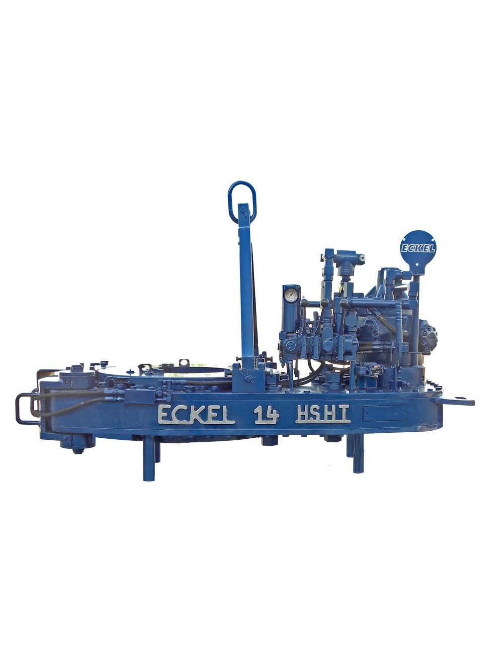
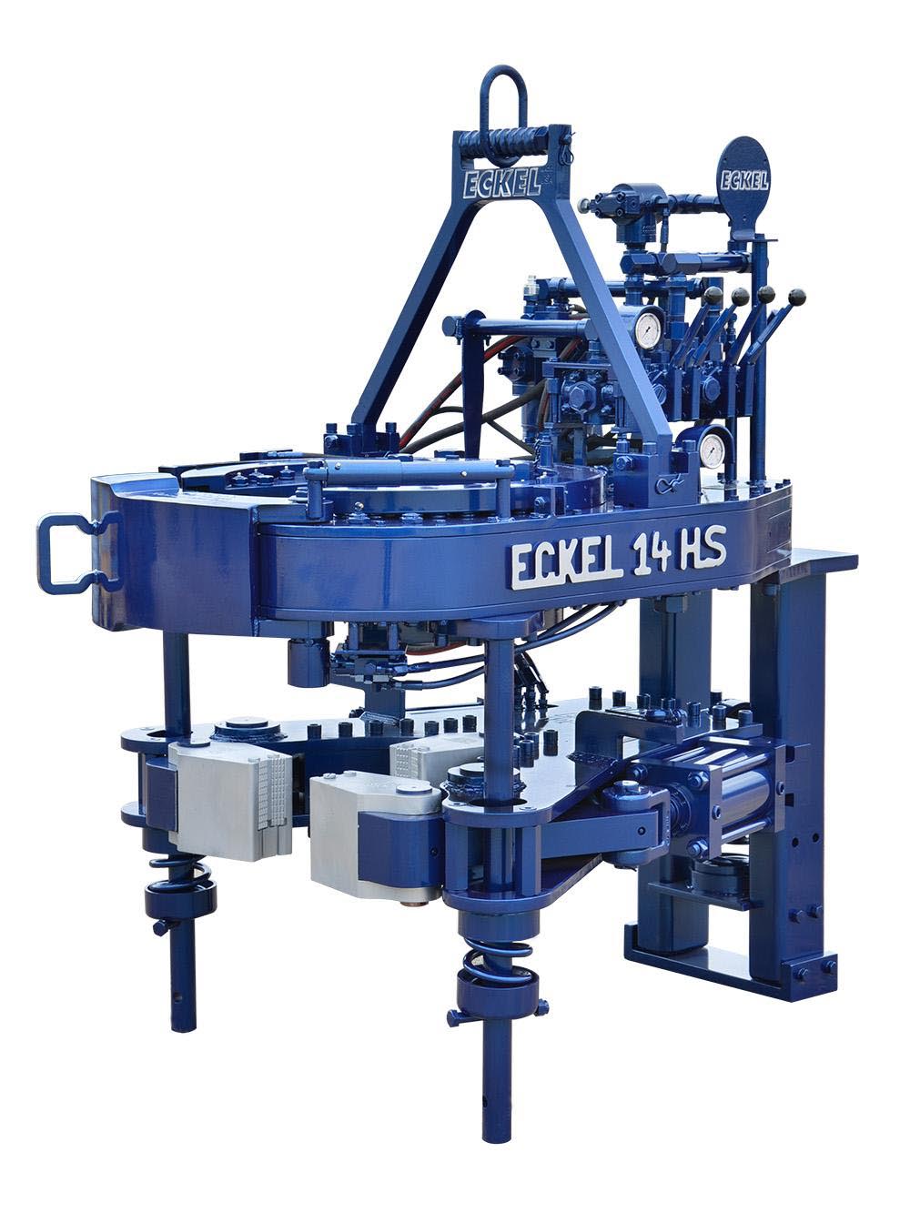
A two-speed Hydra-Shift® motor coupled with a two-speed gear train provides (4) torque levels and (4) RPM speeds. Easily shift the hydraulic motor in low speed to high speed without stopping the tong or tublar rotation, saving rig time.
Used on corrosion resistant alloys (CRA) and fiberglass tubulars where reduced markings on the tubular is desired. Eckel"s Coated True Grit® Dies utilize Tungsten Carbide grit which provides many more points of contact on the surface of the tubular than our Pyramid Fine Tooth dies.
A patented door locking system (US Patent 6,279,426) for Eckel tongs that allows for latchless locking of the tong door. The tong door swings easily open and closed and locks when torque
is applied to the tong. When safety is important this locking mechanism combined with our safety door interlock provides unparalleled safety while speeding up the turn around time between connections. The Radial Door Lock is patented protected in the following countries: Canada, Germany, Norway, United Kingdom, and the United States.
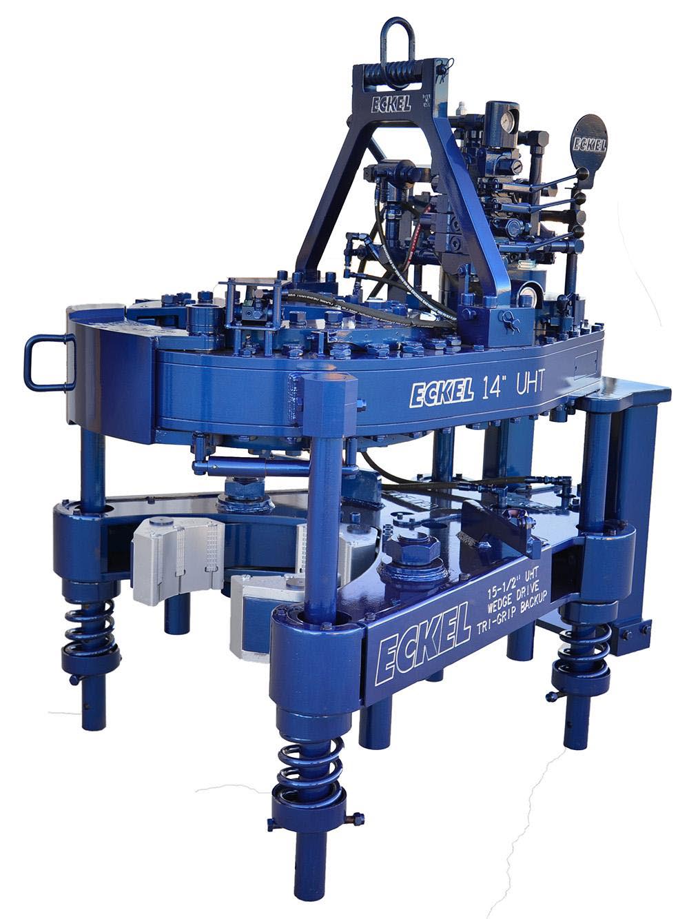
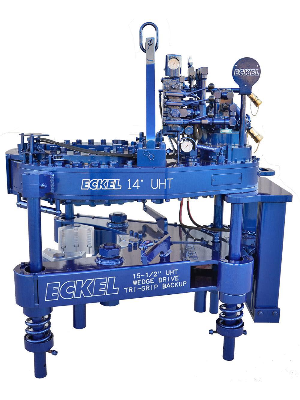
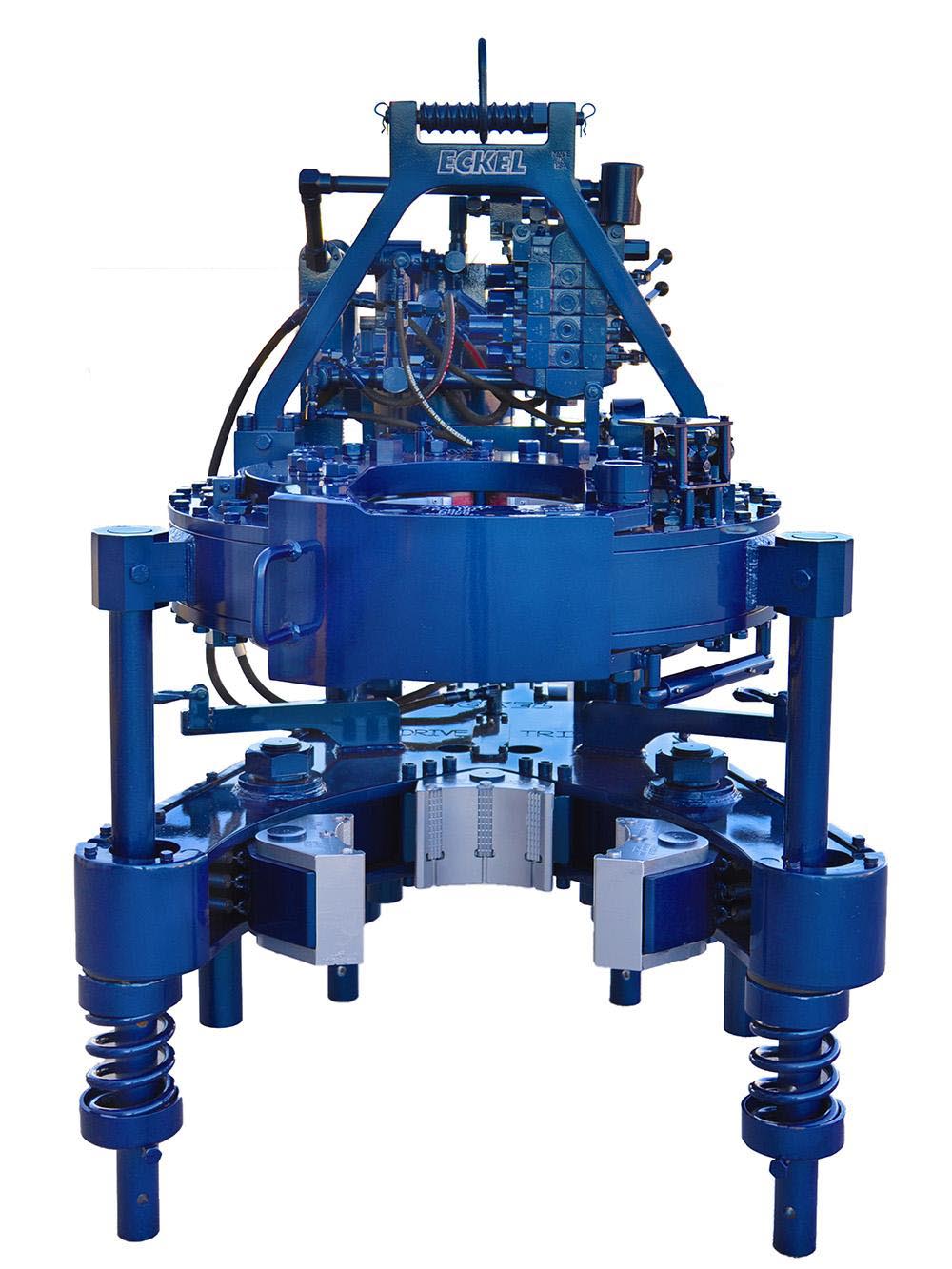
The WD Tri-Grip® Backup is a high performance no compromise backup that is suitable for make-up and break-out of the most demanding connections. The WD Tri-Grip®Backup features a three head design that encompasses the tubular that applies an evenly distributed gripping force. The WD Tri-Grip®is a high performance backup with no compromises that is available for specific applications that provdies exceptional gripping capabilities with either Eckel True Grit® dies or Pyramid Fine Tooth dies.
The field proven Tri-Grip® Backup features a three head design that encompasses the tubular that applies an evenly distributed gripping force. The Tri-Grip®Backup provides exceptional gripping capabilities with either Eckel True Grit® dies or Pyramid Fine Tooth dies. The hydraulic backup is suspended at an adjustable level below the power tong by means of three hanger legs and allowing the backup to remain stationary while the power tong moves vertically to compensate for thread travel of the connection.
Eckel offers several models of torque control systems that are used to monitor the torque turn values when making up tubular connections (Tubing, Casing, & Drill Pipe). Any flaws in the make-up process will be readily shown in a graph.
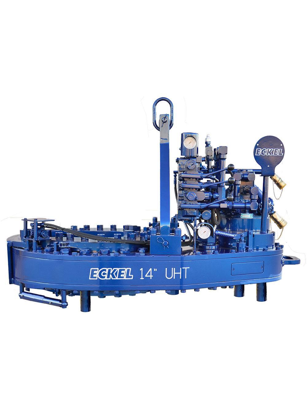
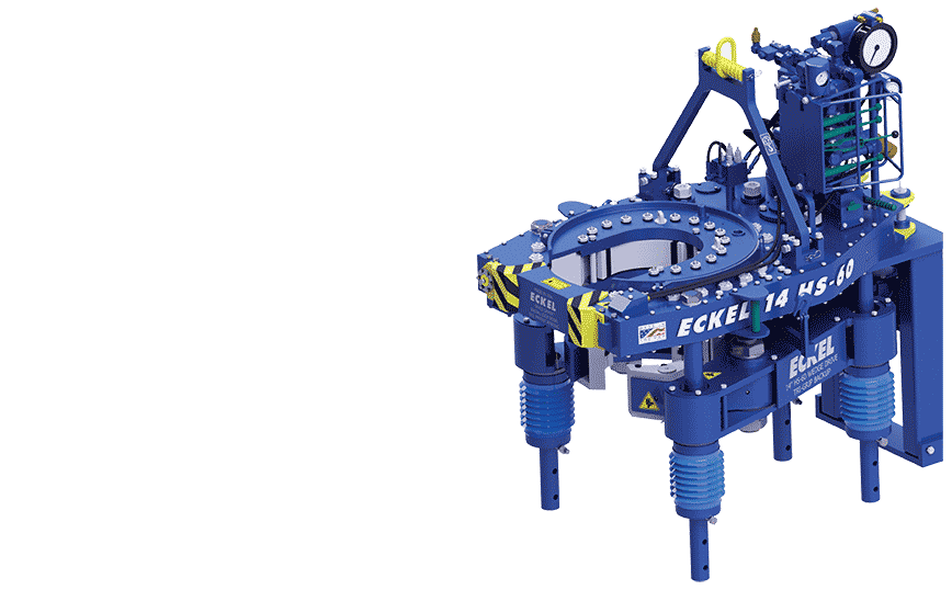
An excellent choice where applications demand the combination of size range and high torque output, the Eckel Model 14 UHT handles pipe from 4 inches to 14 inches. This tong features our new patented CASE STIFFENERS that enhances overall torque output. Upgraded in design and performance over the Model 14 HS, this tong can deliver 70,000 ft-lb of torque. Also, available with Wedge Drive Tri-Grip® backup, which handles pipe from 4 inches to 15.5 inches.
Our patented CASE STIFFENER technology enhances overall torque to provide consistent torque output. Having a high full 360° rotational torque and speed-shifting capability ensures the tong can makeup special torque-turn connections that require continuous rotation. Also, the CASE STIFFENER technology reduces stress and wear on the rotary gear teeth.
The WD Tri-Grip® Backup is a high performance no compromise backup that is suitable for make-up and break-out of the most resilient connections. The WD Tri-Grip® Backup features a three head design that encompasses the tubular that applies an evenly distributed gripping force. The backup is capable of handling tubular from 1.050 in. to 15.5 in. (26.67 - 393.7 mm). A constant radial load is applied when a single wedge drive to actuate the front two pivot heads with a third stationary head providing a reactionary force to provide superior gripping performance. Wedge Drive Tri-Grip® Backup has exceptional gripping capabilities with Rig Dies when running drill pipe or optional Eckel Wrap-Around True-Grit® dies or Pyramid Fine Tooth dies for making up other types of tubular.

I am chairman of the board, president and chief executive officer of Eckel International, the largest global providers of innovative and high performance hydraulic power tongs for the oil and gas industry. I am a second-generation family member involved in manufacturing of tongs. In 1993, as Eckel’s president, I launched an initiative to further reach out to Russia’s oil & gas needs. Today, I am directly responsible for the overall operations of the company, sales, and new market initiatives.
Since 1958 Eckel has been supplying power tongs to the worlds O&G industries– but how long have you been doing business in Russia and what specific solutions do you offer to the region?
Eckel has been conducting business in Russia since the 1978. In 1993, Eckel established an ongoing presence in Russia with CETCO as our local business partner. CETCO further extended our business across Russia & CIS as our local agent. We have observed strength in the Russia and CIS market, with solutions for drill pipe and casing operations.
Eckel specializes in the development of hydraulic power tongs for make-up and break-out of tubulars, with over 60 years of tubular connection experience. Our industry leading technology advancements are in some respects, a reflection on the industry requirements and their needs. Eckel has been in the process of designing tongs that required very high torques, advanced safety features, and automation.
Eckel in-house heating provides quality tempered steel while observing strict industry standards. This process assures high quality and rugged durable parts within Eckel power tongs. Eckel has won a world-wide reputation of providing first-class products that deliver years of trouble free service. Our tongs have operated trouble free in the harsh cold conditions of Western and Eastern Siberia and in the Far Northern Regions. Eckel’s hydraulic power units have a proven track record in some of the harshest surroundings in Russia such as the extreme hot and cold conditions of Russian and offshore environments.
Eckel has provided more than 500 Hydraulic Power Tongs to oil and gas companies and drilling contractors in Russia. In Russia, as well as in many other countries, the use of Corrosion Resistant Alloys (CRA) chrome tubulars are becoming more popular. Eckel is an industry leader in this specialized field tubular connections offering a line CHROMEBOSS® tongs along with Eckel Non-Marking True Grit® dies. True Grit® Dies utilize Tungsten Carbide grit coating which provides many more points of contact on the surface of the tubular than standard Pyramid Fine Tooth dies provide. Penetration depth less than half the depth that is permissible by the American Petroleum Institute (API). Eckel’s True Grit® dies use a dense Tungsten Carbide coating that is a metal like substance which does not flake or sheer off the face of the die. Operational on-site tests have shown that the life time of Eckel True Grit® wrap-around dies is three times longer than competing abrasive powder coated dies. The above equipment and components have been working in Russia several years and proved its advantages.
The hydraulic power tong market is very competitive in Russia, with both local and international suppliers competing for business. Why should a drilling contractor or operator consider using Eckel equipment?
Eckel has over 60 years of experience in this area, and is known for quality and reliability. Many of these tong manufacturers use the old Foster and Hillman Kelly that are 30-year-old designs. Eckel is at the forefront of this industry designing tongs that can handle today’s premium high torque connections. Our tong designs evolved to incorporate additional safety features, automation, and performance. Our new 7.25 HSHT-80 Drill Pipe / Casing and 9-7/8 HS-60 Casing tongs incorporates many of these features.
Eckel has been the leader in development of tubular gripping such as the development of larger wrap-around type dies for many of its tong models. Depending on the application, Eckel offers a coarse tooth, pyramid fine tooth, and our proprietary True Grit dies. Dies are available as rig die style and for thinner wall tubulars where point loading is a concern we offer wrap-around dies. All Eckel equipment is produced at our Odessa, Texas USA manufacturing facilities (ISO 9001:2008 certified) that encompasses 140,663 square feet (13068 square meters) ensures the highest quality.
Eckel equipment is popular world-wide as having shipped to over 100 countries. Eckel is best known for its value in reducing costs, safer tubular connection, reduced maintenance, and mitigated downtime.
Coralina Engineering and Capital Equipment and Trading Corporation (CETCO) has operations in Azerbaijan, and their specialists are intensely involved in this territory. CETCO specialist are successfully making inroads in the Azerbaijan territory offering Eckel power tongs and power units. Additionally, CETCO provides training, classes, assistance, and local experience in all practical aspects of tong operation and maintenance. CETCO is very optimistic for doing business in Kazakhstan region. We are actively working in this region at improving our relationships with existing and new customers.
Eckel continues to improve tong designs, reliability, functionality, and reduce operational costs to comply with today’s oil and gas industry requirements, and anticipate tomorrows industry requirement. A few examples are:
• One of the latest design of a new backup with Wedge Drive Type Tri-Grip which is used on the most of tong models. The WD Tri-Grip is a high-performance backup with no compromises that is available for specific applications. The Wedge Drive Tri-Grip handles the most demanding torques that larger casing and drill pipes demand.
• A new 7.25 HS HT-80 tong, that was introduced in the last half of 2016 for drill pipes and high torque casing pipes. We believe the 7.25 HS HT-80 tong is an extremely needed product for the Russian market. We anticipate the specifications of the tong will be of great interest and welcome surprise for our customers.
• In 2017, Eckel will release a couple of new product designs. The new 9-7/8 HS-60 Casing Tong available the 1st Quarter of 2017 offers efficient and reliable high rotational performance for torque turn jobs. With these high torque ratings, the 9-7/8 HS-60 Casing Tong is capable of properly handling all premium grade tubulars within its size range.
Available in the 2nd Quarter of 2017, a new tong positioner “Tong Handler” that is permanently mounted within the rig which provides a cost effective, safer, and reduced labor-intensive method of maneuvering tongs to the rotary table area on the rig floor.
Russian is a very large and great country with lots of attention dedicated to the oil and gas industries onshore and offshore. Today’s challenge is to have equipment that meets the needs and requirements of oil and gas companies and drilling contractors. Since our first tong delivery in 1978 and now with the assistance of Capital Equipment and Trading Corporation and Coralina Engineering, we have developed a good relationship with many Russian customers and a growing list of new customers. Oil production is not so easy however; we believe that we can solve the most difficult problems facing the oil and gas industries. I have enjoyed visiting Russia many times for work and pleasure.
The 14-100 hydraulic power tong provides 100,000 ft-lb (135,600 N∙m) of torque capacity for running and pulling 7- to 14-in. casing. The tong has a unique gated rotary, a free-floating backup, and a hydraulic door interlock.
Our 14-50 high-torque casing tong provides 50,000 ft-lb (67,790 N∙m) of torque capacity for running and pulling 6 5/8- to 14-in. casing. The tong has a unique gated rotary, a free floating backup, and a hydraulic door interlock.
The 16-25 hydraulic casing tong provides 25,000 ft-lb (33,900 N∙m) of torque capacity for running and pulling 6 5/8- to 16-in. casing. The tong features a unique gated rotary and as many as seven contact points that create a positive grip without damaging the casing.
Rigged up without rig modifications, our 21-300 riser tong is the only tong capable of producing 300,000 ft-lb (406,746 N∙m) of continuous rotational torque in both makeup and breakout mode. The power it achieves in a compact size compares with a conventional 24-in. casing tong.
The 24-50 high-torque casing tong provides 50,000 ft-lb (67,790 N∙m) of torque capacity for running and pulling 10 3/4- to 24-in. casing. The tong features a unique gated rotary, a free-floating backup, and a hydraulic door interlock.
The 30-100 high-torque casing tong provides 100,000 ft-lb (135,600 N∙m) of torque capacity for running and pulling 16- to 30-in. casing. The tong features a unique gated rotary, a free-floating backup, and a hydraulic door interlock.
The 5.5-15 hydraulic tubing tong provides 15,000 ft-lb (20,340 N∙m) of torque capability for makeup and breakout of 1.66- to 5.5-in. tubing and premium or standard connections on corrosion‑resistant alloy tubulars. The tong features an ergonomic, lightweight design with a free-floating hydraulic backup.
The 7.6-30 hydraulic tubing tong provides 30,000 ft-lb (40,670 N∙m) of torque capability for makeup and breakout of 2 3/8- to 7 5/8-in. tubing and premium or standard connections on corrosion‑resistant alloy tubulars. The tong features an ergonomic, lightweight design with a free-floating hydraulic backup.
Our SpeedTork 8.0-70 tong provides torques up to 70,000 ft-lb (94,900 N∙m) and 360° rotation in makeup and breakout operations. It can torque drillpipe connections, drillstring components, drilling tools, packers, couplings, and valves.
Tongs - Power - BJ sucker rod tong adopts advanced sucker rod or tubing technology and has a compact structure, high reliability and is safe and convenient to operate.
Tongs - Power - New Carter Tool Co. Inc., CT93R Hydraulic powered tubing tong. Complete with 2-3/8" to 3-1/2" jaw assemblies, standard motor, torque gauge assembly, pressure relief valve... More Info
Tongs - Power - New Carter Tool Co., Inc. 5-1/2" CTSX Hydraulic Tubing Tong with heavy case and cover; complete with rigid hanger assy., suspension spring assy., front end control assy.,... More Info
Tongs - Power - New Carter Tool Co. Inc. M-Series power sucker rod tongs, complete with spring hanger assy., gate assy., front end control assy., pressure gauge assy., two 90 degree XH s... More Info
Tongs - Power - New Carter Tool Co., Inc. 4-1/2" RSX Hydraulic Tubing Tong with heavy case and cover; complete with rigid hanger assy., suspension spring assy., front end control assy., ... More Info
Tongs - Power - D D 58-93-2-R Power Tubing Tong is smaller, lighter, and faster than the Foster 5893R. The D D 58-93-2-R Tong is capable of gripping tubulars from 1 5/16" to 7" o.d. More Info
Tongs - Power - FARR TONG MODEL KT 14,000 RINEER GA37 MOTOR, LIFT VALVE ASSEMBLY TORQUE CAPACITY: 50,000 FT/LB SIZE RANGE 4 1.2-14 WITH SAFETY DOOR MOST SIZES OF FARR POWER TONGS ARE IN ... More Info
Tongs - Power - FARR TONG MODEL KT20,000 STAFFA 080 MOTOR, LIFT VALVE ASSEMBLY TORQUE CAPACITY: 50,000 FT/LB SIZE RANGE: 7-20 MOST SIZES OF FARR POWER TONGS ARE IN HOUSTON, IN STOCK READ... More Info
Tongs - Power - FARR MODEL KT5500 HYDRAULIC TUBING TONG C/W 2 SPEED RINEER MOTOR, SIZE RANGE: 2-3/8 IN. - 5-1/2 IN. OD, TORQUE RTED: 18,700 FT/LB C/W SAFETY DOOR MOST SIZES OF FARR POWER... More Info
Tongs - Power - FARR TONG MODEL KT5500 TORQUE CAPACITY: 18000 FT/LB SIZE RANGE: 2 1/16-5 1/2 OD WITH SAFETY DOOR MOST SIZES OF FARR POWER TONGS ARE IN HOUSTON, IN STOCK READY FOR IMMEDIA... More Info
Tongs - Power - FARR TONG MODEL KT5500 5 1/2 IN. TONG TORQUE CAPACITY: 18,000 FT/LB SIZE RANGE: 2 1/16-5 1/2 IN. OD, RINEER 15-13 MOTOR, HIGH TORQUE CLINCHER BACKUP TRIPLE VALVE ASSEMBLY... More Info
Tongs - Power - FARR TONG MODEL KT7585 TORQUE CAPACITY: 25000 FT/LB SIZE RANGE: 2 1/16-8 5/8 OD WITH SAFETY DOOR MOST SIZES OF FARR POWER TONGS ARE IN HOUSTON, IN STOCK READY FOR IMMEDIA... More Info
Tongs - Power - FARR TONG MODEL KT7585 8 5/8 IN. TONG TORQUE CAPACITY 25,000 FT/LB SIZE RANGE: 2 1/16-8 5/8 IN. OD, RINEER 15-15 MOTOR CLINCHER BACKUP, TRIPLE VALVE MOST SIZES OF FARR PO... More Info
Tongs - Power - FARR TONG MODEL LW9625 TORQUE CAPACITY 12000 FT/LB SIZE RANGE 2 7/8 -9 5/8 OD WITH SAFETY DOOR MOST SIZES OF FARR POWER TONGS ARE IN HOUSTON, IN STOCK READY FOR IMMEDIATE... More Info
Tongs - Power - Farrs newest tubular connection tool offers a significantly reduced rig footprint, while continuing to deliver power & uncompromising reliability. The simple design drast... More Info
Tongs - Power - Farr Canada"s newest tubular connection tool offers a significantly reduced rig footprint, while continuing to deliver power and uncompromising reliability. The simple de... More Info
This invention is directed to apparatus and methods for aligning wellbore tubulars; and to power tongs used in making and breaking joints of tubular members such as wellbore casing and tubing; to parts thereof; including, but not limited to gripping elements, and methods of their use.
During the drilling of oil and gas wells and the production of materials therefrom, various operations require the connection and disconnection of successive lengths of threaded tubulars such as pipe, casing, or tubing. Tools known as tongs are used to "make" and "break" such connections. Certain known power tongs have a body, a rotary rotatably mounted in said body and at least one active jaw which, on rotation of the rotary is cammed against a pipe in the rotary and grips it for rotation with the rotary. In known arrangements the camming action is generated by a cam member which is bolted to the rotary and is shaped so that the active jaw is cammed against the pipe on rotation of the rotary relative to the active jaw in one sense and will be released on rotation of the rotary relative to the active jaw in the opposite sense.
With known tongs high torques are applied to tubulars due to combinations of factors such as thread sealing requirements, the presence of corrosion, the existence of distortion, and pipe size and weight. Both in the "make" direction of rotation when a shoulder is suddenly encountered, and in the "break" direction at initial engagement of the tong and disengagement of the threads high shock forces may arise; e.g., with a power-driven tong, in excess of 50,000 foot-pounds of torque may be exerted, while relatively small die elements on jaws of the tong engage the pipe with extremely high force loadings. Slippage occurs and pipe surfaces become marred, marked, indented, or otherwise damaged.
Dies for gripping jaws have been provided with multiple serrations, or penetration features, to provide the interference contact at the joint surface. Grip element penetration into the joint surface is limited and controlled. The distribution and balance of grip element energizing forces are critical factors in the design, development and evaluation of such tong mechanisms. Linkages, levers, wedges, and cams are used to balance force components. Grip elements, or dies, are accurately disposed within carrier bodies, or jaws, which span a circumferential segment of the joint surface.
Uneven die loading can cause excessive indentation, marring or damage to a tubular surface. Drag or braking devices are used in certain tongs to effect proper biting of the dies relative to the pipe. The head or other member supporting the dies is frictionally restrained to insure that the dies do not simply rotate with the rotary as the rotary is driven.
Other tongs use an endless belt, chain or flexible material loop for gripping a tubular. Such tongs are disclosed in U.S. Pat. Nos. 3,799,010; 3,906,820; 3,892,140; 4,079,640; 4,099,479; and 4,212,212. There are a variety of problems associated with certain of these tongs:
Jaw/die tongs and the belt/chain tongs are used with relatively hard and rigid metal tubulars such as casing and tubing. If these tongs are used with thick tubulars or tubulars made from relatively "softer" metals or from premium metals such as high alloy steels or low carbon steels or tubulars made from non-metal materials such as fiber glass, they often literally chew up the tubular. The use of strap wrenches is inadequate since the torque applied with such wrenches cannot be precisely controlled.
Certain tubulars are treated with a rust or corrosion resistant material or coating. If the coating is indented, gouged, or broken, its protective purpose is defeated. Producing enough force in a tong to join such tubulars while not injuring a protective coating presents a dilemma.
The present invention, in certain embodiments, discloses a power tong for joining tubulars so that marking of, indentation of, and surface injury to tubulars are reduced or eliminated. In one aspect a power tong is provided and a method of its use for handling tubulars coated with a corrosion-resistant material which should not be broken or penetrated. In one embodiment such a tong has one or more gripping jaws with gripping elements made of aluminum alloys, zinc, zinc alloys, aluminum, brass, bronze, cermet, plastic, fiberglass, metal alloys, or a combination thereof which present a smooth face (straight or curved) to a tubular without any teeth, pointed projections, or toothed dies. In one aspect the gripping elements are releasably connected directly to jaws. In another aspect the gripping elements are releasably connected to a jacket or holder which itself is releasably connected to a jaw.
In one aspect the cylinder(s) are powered by a small air-driven hydraulic pump with an hydraulic fluid reservoir mounted on a plate on the movable or fixed jaw. Air is supplied to activate a motor of the pump and the pump then provides hydraulic fluid to move a piston of the hydraulic cylinder(s). The motion of the cylinder moves the movable jaw on its roller to travel to a pre-load position on the cam. The cylinder applies pressure until the hydraulic pressure is released. A hydraulic fluid accumulator and a valve may be used to maintain hydraulic pressure at all times so that the cylinder(s) continuously maintain the desired load on the jaw until the air supply to the pump is removed.
In another aspect the cylinders are connected to a rotary of the tong or to any other member that rotates with the rotary rather than to a fixed jaw. Such a pre-load system may, according to this invention, be used with any tong including a tong that does use toothed dies.
In one embodiment the present invention discloses a gripping arrangement for a tong with a sheet of grit which is preferably bonded to a carrier plate. In another embodiment the gripping arrangement comprises a layer of flexible material having a smooth flat surface or a surface with ridges and valleys, for example in the fashion of the surface of a file. The flexible material, in one aspect, is metal, for example sheet aluminum, zinc, brass, bronze, zinc alloy, aluminum alloy, stainless steel, or steel having a thickness of about 1.5 mm. The layer of flexible material may be used in conjunction with a carrier plate or on its own. In a further embodiment the gripping arrangement may comprise a layer of perforate material one of both surfaces of which are preferably coated with grit to facilitate adhesion. The layer will typically be formed from metal having a thickness of about 1.5 mm. The layer may be used in conjunction with a carrier plate or used on its own. In yet another embodiment the gripping arrangement may comprise a layer of expanded mesh, e.g. metal mesh, which has been flattened. One or both surfaces of the expanded mesh may be coated with grit and the layer may be used in conjunction with a carrier plate or used on its own. The grit may comprise, for example, diamond dust, particles of silicon, zircon, tungsten carbide and mixtures thereof. The gripping arrangement may comprise end plates which are attached to the carrier plate. Preferably, the carrier plate is provided with side flanges for insertion into a jaw holder. The present invention also provides a jaw assembly fitted with a gripping arrangement in accordance with the present invention. Preferably, the jaw assembly includes a jaw holder having an arcuate recess which accommodates an arcuate pad of resilient elastomeric material which supports said gripping arrangement. Advantageously, at least one shim is provided which is disposed between said arcuate pad of resilient elastomeric material and said gripping arrangement. The shim will be flexible and generally from 0.5 mm to 1.0 mm thick and made from sheet metal. The present invention also provides a tong fitted with at least two such jaw.
In one embodiment the present invention discloses an apparatus for aligning tubulars and includes a guide on one of a power tong and a backup tong. In one embodiment the apparatus has a socket centralizer mounted on said one of said power tong and said backup tong. In one aspect, said one of said power tong and said backup tong is said power tong. In another embodiment, the apparatus includes a power tong and a backup tong, and the guide is mounted on the power tong and apparatus is provided to maintain the power tong and the backup tong in a certain juxtaposition during a stabbing operation. Preferably, said apparatus includes locating rods on one of the power tong and the backup tong and blocks shaped to receive at least the ends of the locating rods on the other of the power tong and the backup tong. Advantageously, the backup tong is provided with at least two prismatic jaw assemblies to locate the backup tong in fixed juxtaposition with respect to a tubular being gripped.
The present invention, in one aspect, provides a jaw unit for use in a tong, which jaw unit comprises a jaw holder and a jaw movable with respect to said jaw holder, characterized in that said jaw is slidably mounted on said jaw holder. Preferably, said jaw is slidable with respect to said jaw holder about an arcuate path. Advantageously, said jaw has a gripping surface which is substantially arcuate for gripping the surface of a tubular and the center of curvature of such arcuate path lies between the center of curvature of said grip ping surface and said arcuate path. The gripping surface may be a continuous surface or defined by several spaced apart gripping elements. Preferably, the center of curvature of said arcuate path lies between the center of curvature of said grip ping surface and said gripping surface. Advantageously, the center of curvature of said arcuate path is substantially midway between the center of curvature of said gripping surface and said gripping surface. Preferably, one of said jaw and said jaw holder is provided with an arcuate track which defines said arcuate path, and the other of said jaw and said jaw holder is slidably mounted in said arcuate track.
The present invention also provides a jaw assembly comprising two jaw units in accordance with the present invention. Preferably, said jaw units are mounted for pivotal movement about a common pivot shaft. Advantageously, said jaw assembly includes means which bias said jaw units apart. The present invention also provides a rotary fitted with a jaw unit in accordance with the present invention, a rotary fitted with a jaw assembly in accordance with the present invention, and a tong fitted with a rotary in accordance with the present invention.
One of the features of existing tongs is that their rotaries are difficult to furnish. Thus, routine maintenance usually involves dismantling the whole rotary, checking the parts and reassembling the whole. While this is a straightforward procedure in the clean conditions of a workshop it can be problematic when carried out in a muddy field, in sand or in snow. The present invention aims to help solve this problem and provides a rotary which comprises a top section, a bottom section, and a peripheral wall therebetween, characterized in that at least one of said top section and said bottom section is provided with an elongate slot which, when said rotary is in use, accommodates a pivot shaft on which a jaw assembly can be pivotally mounted.
Jaw holders and jaws for tongs are traditionally machined from a solid piece. This is a comparatively expensive procedure. The present invention proposes to make such parts from a stack of individually cut laminations.
Such methods and devices including a power tong with at least one jaw with at least one tubular gripping element having a smooth gripping surface (flat or curved) and, in one aspect, such an element which is flexible;
FIG. 2A is a perspective view of a tubular connection system according to the present invention. FIGS. 2B and 2C are perspective views of a casing tong of the system of FIG. 2A.
FIG. 5A shows schematically an initial position of elements of a tong system according to the present invention. FIG. 5B shows pre-loading on a pipe of the jaws of the system of FIG. 5A. FIG. 5C shows a tubular gripped with the system of FIG. 5A.
FIG. 14 is a front elevation of a first embodiment of a flexible gripping member in accordance with the present invention and which is used in the jaw assembly shown in FIGS. 10 to 13.
FIGS. 1A-1C show a typical prior art power tong that uses fixed jaws and a movable jaw to grip pipe for tubular disconnecting and connecting operations. An outer case houses a powered rotary to which the jaws are mounted. A cam surface of the rotary moves a movable (ACTIVE or MASTER) jaw into (and away from) gripping contact with a tubular, e.g. pipe. Each jaw has toothed gripping inserts to facilitate engagement with the surface of the tubular (see FIG. 1B). FIG. 1C shows the tong in an "OPEN" position in which the tubular is not gripped.
The tong shown in FIG. 1A is a Weatherford Model 14.5-50 High Torque Tong. The brochure "New ! Weatherford Model 14.5-50 High Torque Tong," (1991) and the manual entitled "Model 14.5-50 Hydraulic Power Tong Installation, Operation and Maintenance" (1993) are submitted herewith and incorporated herein fully by reference for all purposes. It is to be understood that the teachings of the present invention are applicable to any tong and any tong system that has one or more gripping elements or jaws and that the Model 14.5-50 tong is shown here for illustrative purposes and not by way of limitation of the scope of the present invention.
As shown in FIG. 2A a system 10 according to the present invention includes a power tong 100 according to the present invention which is like the tong of FIG. 1A but which also includes a unique jaw system 110 with inserts 150 on fixed jaws 120 and insert 152 on movable jaw 122 and at least one jaw pre-load assembly like that shown in FIG. 5A. The system 10 includes a free floating backup tong 12.
As shown in FIGS. 2B and 2C, rods 112 are connected to the movable jaw 122. The inserts 150 are on fixed jaws 120 and the insert 152 is on a movable jaw 122 (corresponding to the fixed jaws and active jaw, respectively, of the tong of FIG. 1A).
FIGS. 4A-4G illustrate an alternative jaw mounting system in which holders are interposed between jaw bodies and inserts. The holders protect the jaws from damage if the inserts wear down and a variety of different types and/or sizes of inserts may be used with and interchanged on a single holder. In one aspect it is within the scope of this invention to use these holders to mount conventional toothed dies to a tong jaw and to use them for easy substitution of new and/or different dies.
FIG. 4A shows a jaw system 400 for a tong (like the tong of FIG. 2A) which has two fixed jaws 402 and a movable (movable toward and away from a tubular to be gripped 403) jaw 404. Each jaw 402 has a jaw body 405 with a holder 406 secured thereto. In one aspect dovetail keys 407 secured to the holder or releasably mounted thereto fit in corresponding slots 408 of the jaw bodies 405 to releasably mount the holder 406 to the body. In one aspect dovetail keys 409 releasably mount the holders 406 to jaw bodies 405. The dovetail keys 409 are releasably held in corresponding recesses 411 in the holders 406. One or more dovetail keys 409 may be used (two shown for each holder 406).
An insert 420 has dovetail keys 421 received and held in corresponding slots 422 of the holder 414. The insert 420 is shown as a single unitary insert but a plurality of individual inserts (either abutting or spaced apart) may be used secured to the jaw body 415.
FIG. 5A shows a tong system 500 with a tong having a movable rotary 502, fixed jaws 504, 505, and a movable jaw 506 (remainder of tong, not shown, like the tong of FIG. 2A; like the tong of FIG. 1A, but with the added features discussed here). Pins 520 pin the fixed jaws to the rotary. Inserts 522 on the fixed jaws 504, 505 are like the inserts described herein for other fixed jaws. Insert 524 on the movable jaw 506 is like other inserts described herein for movable jaws. A pre-load cylinder 508 to assist in make-up is pivotably connected at one end to the fixed jaw 505 and at the other end to the movable jaw 506. A pre-load cylinder 510 to assist in break-out is pivotably connected at one end to the fixed jaw 504 and at the other end to the movable jaw 506. It is within the scope of this invention for the ends of cylinders connected to the fixed jaws to instead be secured to the rotary or to a support ring or other member that rotates with the rotary. It is within the scope of this invention to employ one cylinder interchangeable between the positions of the cylinders 508 and 510 (FIG. 5A) or one cylinder connectible to the fixed jaw 506 at one end for break-out and at the other end of the fixed jaw 506 for make-up with the other cylinder end secured to the rotary. Rollers 530 rotatably mounted on the movable jaw 506 co-act with cam surfaces 532 on the rotary 502 to move the jaw 506 to operative and inoperative positions.
Air in a line 640 selectively applied with a control system 650 (e.g. mounted on the rig floor, on the tong or remote controlled) selectively actuates the pump 630 to pump fluid through the valve 602 to the pre-load cylinders. The directional control valve 602 is either manually operated or operated by remote control. Correct fluid pressure is monitored with a gauge 651.
As shown in FIG. 5C the tubular 650 has been gripped due to the action of the pre-load cylinder 510 with a suitable pre-load force (e.g., but not limited to, about 500, 1000, 5000, 10000 or 50000 pounds of force). This force is sufficient that when the rotary 502 of the tong is rotated the jaws do not slip on the tubular 650; but the pre-load force is sufficiently low that the jaws do not mark or damage the tubular 650.
FIG. 8 shows schematically a top view of a power tong according to the present invention. A power tong T has an hydraulic motor M with control/monitor apparatus C on a tong case S. A movable jaw J is moved and rotated by a rotary R which is moved by interconnection, via appropriate gearing, by the motor M. Fixed jaws F and G are secured to the rotary R. A first pre-load cylinder D connects the movable jaw J to the fixed jaw G for applying a pre-load to the movable jaw for make-up operations. A second pre-load cylinder L connects the movable jaw J to the fixed jaw F for applying a pre-load to the movable jaw for break-out operations. An insert I (any insert disclosed herein) is secured to the movable jaw J and inserts K (any insert disclosed herein) are secured to the fixed jaws F and G.
FIG. 9 shows a tong jaw 450 according to the present invention with an insert 454 (any insert disclosed herein) and rods 452 secured thereto, e.g. by welding. The rods 452 provide a member to which either a cylinder body or a piston of a pre-load piston cylinder apparatus is connectible. Instead of the rods 452 as shown which extend from above the jaw 450 to a point below it, only rod sections may be used secured to one or both sides of the jaw to provide a securement member for an end of a pre-load apparatus.
According to the present invention a variety of apparatuses and devices may be employed to pre-load a tong jaw having one or more smooth faced gripping insert elements thereon. In one aspect a manually activated pre-load cylinder is used which has fluid or material manually introduced therein to apply a pre-load or manually removed therefrom to release a pre-load. In another aspect a pre-load cylinder is pivotably secured at one end to a rotary or part thereof and the other end is releasably connectible to either end of a movable jaw so that a pre-load may be applied, selectively, to either end of the movable jaw for make-up or break-out operations as desired. In one aspect such a pre-load cylinder has a rod with an end member receivable in and movable in a slot in the movable jaw or there are recesses at either end of the jaw for holding the end member of the rod so that a pre-load can be applied. A secondary small cylinder may be used to selectively move the pre-load cylinder in the jaw slot or it can be moved manually. In another embodiment the tong"s movable jaw has one or more upwardly projecting lugs engageable by a forked piston rod end of a pre-load piston/cylinder that is attached to the rotary. The rotary is rotated so that the jaw is cammed into the pipe to be rotated in a pre-load position and then the forked rod is removed for further tong operations.
The jaw assembly 1001 comprises a jaw holder 1002 which is provided with an arcuate recess 1003 which accommodates an arcuate pad 1004 of resilient elastomeric material. A block 1005 of steel is molded into each end of the arcuate pad 1004 as shown. Three thin shims 1006 of metal each having a thickness of about 0.5 mm are positioned on the inner surface of the arcuate pad 1004 and support an insert or gripping arrangement 1007 which comprises a carrier plate 1008 and a friction layer 1009. The carrier plate 1008 has side flanges 1010 and 1011 which clip over the blocks 1005 as shown. The top and bottom of the carrier plate 1008 are tack welded to end plates 1012 and 1013 which are bolted to the jaw holder 1002 by socket screws 1014. The friction layer 1009 comprises a sheet of zircon paper which is bonded to the carrier plate 1008. The carrier plate 1008 is made of sheet steel and is approximately 1.5 mm thick. As such it is quite flexible.
In use, two or more jaw assemblies are placed in a tong and are disposed around a length of casing. The jaw assemblies 1001, 1001" are then advanced radially inwardly in the direction of arrows "A" (FIG. 12) until they engage and firmly grip the casing. Because of the flexible construction of the gripping arrangement 1007, the shims 1006 and the arcuate pad 1004, the friction layer 1009 substantially conforms to the circumference of the casing and grips the casing with a substantially uniform gripping action. Once the casing has been firmly gripped the jaws are rotated by the tong in the usual manner. It will be noted that circumferential forces applied to the friction layer are transmitted through the carrier plate 1008 so that any local loads caused, for example by an irregularity in the surface of the casing are redistributed by the carrier plate 1008 and transmitted to the jaw holder 1002 via the side flange 1011 and the arcuate pad 1004 (see FIG. 18).
In use, the gripping arrangement 1007 can be rapidly replaced simply by unscrewing the socket screws 1014, removing the end plates 1012 and 1013 together with the gripping arrangement 1007 and installing a new arrangement. Because it is normally essential to minimize replacement time the gripping arrangement 1007 will normally be supplied complete with end plates 1012 and 1013. The gripping arrangement 1007 may be removably mounted on the end plates 1012 and 1013 if desired.
Referring to FIGS. 19A and 19B of the drawings there is shown a conventional tong assembly which is generally identified by the reference numeral 2001.
The power tong 2002 comprises a pair of gates 2004, 2005 which are held together in the position shown by latch 2006. When the latch 2006 is released the gates 2004, 2005 can be swung open by admitting hydraulic fluid to piston and cylinder assemblies 2007 and 2008. The power tong 2002 also contains a rotary 2009 which is provided with four jaw assemblies 2010. The rotary 2009 can be rotated by a hydraulic motor 2011.
The backup tong 2003 is provided with two gates 2012, 2013 which are held together by latch 2014 but which, when latch 2014 is released can be swung to an open position.
Once the pin is correctly located the stabbing guide is removed. The gates 2004, 2005 of the power tong 2002 and the gates 2012, 2013 of the backup tong 3 are then opened and the tong assembly 2001 moved towards the casing until the lower length of casing lies within the backup tong 2003 and the upper length of casing lies within the power tong 2002. The gates 2004, 2005, 2012, 2013 are then closed and latched. Jaw assemblies in the backup tong are then advanced to engage the lower length of casing while jaw assemblies in the power tong 2002 are advanced to grip the upper length of casing. The hydraulic motor 2011 is then actuated to turn the rotary 2009 and rotate the upper length of casing relative to the lower length of casing. The tong assembly 2001 is supported by a pneumatic lifting cylinder 2015 which enables the power tong 2002 to move towards the backup tong 2003 as the pin enters the socket. Reaction forces are transmitted by columns 2016 disposed to either side of the tong assembly 2001 and by a series of levers in a known manner. It should be noted that the power tong 2002 is free to move in a plane parallel to the backup tong 2003 within certain limits.
The apparatus 2100 comprises a tong assembly 2101 which is generally similar to the tong assembly 2001 shown in FIGS. 19A and 19B and parts of the tong assembly 2101 similar to the tong assembly 2001 have been identified by similar reference numerals in the "2100" series.
Turning first to the guide 2117 it will be seen from FIG. 21B that this comprises four identical components 2118 which are bolted to the top of the power tong 2102. As best shown in FIG. 21C each component is tapered so as to guide the pin of an upper casing to the center of the opening of the power tong 2102.
Referring now to FIG. 22, the backup tong 2103 is provided with three prismatic jaw assemblies 2119a, 2119b, and 2119c which, when actuated, hold a lower length of casing 2120 in a fixed position relative to the backup tong 2103.
As shown in FIG. 23 the backup tong 2103 is provided with three upwardly extending locating rods 2121 which are each provided with a conical tip 2122. Similar, the underside of the power tong 2102 is provided with three blocks 2123 each of which is provided with a recess 2124 shaped to receive the conical tip 2122 of a respective locating rod 2121.
In use, the lower length of casing 2120 is first secured by slips on the rig floor in the usual manner. The gates 2112 and 2113 of the backup tong 2103 are then opened and the tong assembly 2101 moved into position with the backup tong 2103 circumjacent the lower length of casing 2120 and immediately below the socket 2125 thereof.
The gates 2112 and 2113 are then closed by hydraulic piston and cylinder assemblies 2126 and 2127 and the latch 2114 closed. The prismatic jaw assembly 2119a is fixed while prismatic jaw assemblies 2119b and 2119c are automatically advanced by a predetermined distance when the latch 2114 is closed. This grips the lower length of casing firmly and also ensures that the backup tong 2003 is in a fixed position relative to the lower length of casing 2120. The position thus far attained is shown in FIG. 23.
At this time pneumatic lifting cylinder 2115 is extended which lowers the backup tong 2003. The conical tips 2122 of the locating rods 2121 enter the recesses 2124 of the blocks 2123 and thus locate the power tong 2002 with respect to the backup tong 2003. This in turn locates the guide 2117 with respect to the lower length of casing 2120 so that the center of the guide 2117 is coaxial with the axis of the lower length of casing 2120. This position is shown in FIG. 24.
The power tong 2102 is then raised so that the blocks 2123 are well clear of the locating rods 2121. At this point the jaw assemblies in the power tong 2102 are applied to the upper length of casing 2128 and the hydraulic motor 2111 actuated to rotate the rotary and screw the pin 2129 into the socket 2125. During the procedure the power tong 2102 moves towards the backup tong 2103. However, even when the joint is tightened to the required torque the blocks 2123 still lie a short distance above the conical tips 2122 of the locating rods 2121.
At this stage the jaw assemblies of both the power tong 2102 and the backup tong 2103 are relaxed, the gates 2104, 2105, 2112 and 2113 opened and the tong assembly 2101 retracted in preparation for the casing being lowered. It will be noted that one component 2118 of the guide 2117 is mounted on each of the gates 2104, 2105 and accordingly the guide 2117 opens and closes with the gates 2104, 2105.
For certain applications a backup tong is not required, for example where the power tong can conveniently be restrained by a chain attached to the drilling tower.
The apparatus 2200 comprises a power tong 2202 which is generally similar to the power tong 2002. The basic construction of the power tong 2202 is similar to the power tong 2002 and parts having similar functions have been identified by the same reference numeral in the "2200" series.
The main differences are that the apparatus 2200 does not include a backup tong and that it is provided with a guide 2217 and a socket centralizer 2230.
In use, the lower length of casing 2220 is first secured by slips (not shown) with the socket 2225 facing upwardly close to the slips. The power tong 2202 is then lowered onto the socket 2225 so that the socket 2225 enters the socket centralizer 2230 and aligns the socket centralizer 2230, the socket 2225 and the guide 2217. The upper length of casing 2228 is then lowered so that its pin 2229 enters the guide 2217, is center there by and enters the socket 2225. At this point power tong 2202 is raised. Its jaw assemblies are then advanced to grip the upper length of casing 2228 which is then rotated to screw the pin 2229 into the socket 2225. Once the joint is tightened to the required torque the gates 2204, 2205 are opened and the power tong 2202 withdrawn.
The embodiment shown in FIG. 29 is generally similar to that shown in FIG. 28 except that the apparatus 2300 also includes a backup tong 2303. Since the upper length of casing 2328 and the lower length of casing 2320 are being aligned by the guide 2317 and the socket centralizer 2330 no special arrangements need be made for aligning the power tong 2302 and the backup tong 2303.
The procedure for connecting the upper length of casing 2328 to the lower length of casing 2320 is as follows. First, the lower length of casing 2320 is secured in slip (not shown). The gates 2312, 2313 of the backup tong are then opened and the apparatus 2300 maneuvered so that the lower length of casing 2320 is disposed within the backup tong 2303. The power tong 2302 is then lowered until the socket 2325 on the lower length of casing 2320 is received within the socket centralizer 2330. The upper length of casing 2328 is then lowered until the pin 2329 passes through guide 2317 and enters the socket 2328. Only at this stage are gates 2312, 2313 closed and the jaw assemblies of the backup tong 2303 activated to grip the lower length of casing 2320. The power tong 2302 is then raised and its jaw assemblies activated to grip the upper length of casing 2328 which is then rotated to cause the pin 2329 to enter the socket 2325 and the joint to be tightened to the desired torque. The jaw assemblies are then relaxed and the gates 2304, 2305, 2312, 2313 of the power tong 2302 and the backup tong 2303 opened prior to retracting the apparatus 2300.
Various modifications to the embodiments described are envisaged, for example, if desired, the guide and the socket centralizer could be mounted on the backup tong 2303 rather than the power tong 2302. Alternatively, the guide could be mounted on the backup tong without a socket centralizer. Such an arrangement is shown in FIG. 30.
The embodiment shown in FIG. 30 is generally similar to that shown in FIG. 19a and 19b and parts of the tong assembly 2401 similar to the tong assembly 2001 have been identified by similar reference numerals in the "2400" series. One difference is that the top of the backup tong 2403 is provided with a guide 2417.
In use, the lower length of casing 2420 is first secured by stops 2431 on the rig floor in the usual manner. The gates 2412 and 2413 of the backup tong 2403 are then opened. Since two of the four components 2418 of the guide 2417 are mounted on the gates 2412 and 2413 the guide 2417 opens with the gates 2412 and 2413 so that the lower length of casing 2420 can enter the backup tong 2403 when the carriage 2432 which supports the apparatus 2400 is advanced towards the casing 2420 on rails 2433. When the lower length of casing 2420 is fully within the backup tong 2403 the gates 2412 and 2413 are closed. The components 2418 of the guide 2417 have a stepped interior (not visible in FIG. 30) so that the lower part of each component 2418 touches the socket on the top of the lower length of casing 2420 whilst the upper part of the interior of each component 2418 tapers inwardly to form a funnel. Once the lower length of casing 2420 has been gripped the upper length of casing 2428 is lowered through the power tong 2402 towards the lower length of casing 2420. The guide 2417 guides the pin on the bottom of the upper length of casing 2428 into the socket. The power tong 2402 is disposed a small distance above the guide 2417. Once the pin of the upper length of casing 2428 has entered the socket on the lower length of casing the jaws of the power tong 2402 are applied to the upper length of casing 2428 which is rotated until the joint reaches the desired torque.
FIG. 33 shows the tubular 3111 contacting the jaws 3106. As the tubular 3111 is further advanced towards the center 3110 of the rotary 3100 the jaws 3106 are displaced in the direction of the arrows 3114 until they come to rest in the position shown in FIG. 34. It will be noted that the arcuate track 3108 is no longer visible.
Referring now to FIG. 38, the rotary 3100 is shown fitted in a tong 3116. As shown in FIG. 39 and 40, the rotary 3100 is formed as a one piece casting which comprises a top section 3117, a bottom section 3118, and a peripheral wall 3119 on which is formed a toothed track 3120. Both the top section 3117 and the bottom section 3118 are provided with an elongate slot 3121, 3122 respectively. Each elongate slot 3121, 3122 has its center of curvature on the center of rotation of the rotary 3100.
As can be seen in FIG. 38 and FIGS. 31 to 37, the sides of the rotary 3100 are provided with cams 3128, 3129, 3130 and 3131 which are screwed to the rotary 3100. The rotary 3100 is located in the tong 3116 by nine guide rolls 3132, five of which are visible in FIG. 38. The guide rolls 3132 each have an upper and a lower roller which bears against the peripheral wall 3119 of the rotary 3100 above and below the toothed track 3120 respectively.
The present invention relates to power tongs utilized to make up or break apart pipe members and, more particularly, relates to back-up tongs utilized to secure a pipe member against rotation. The present invention also relates to tongs of the scissors type, wherein an upper body portion rotates relative to a lower body portion to achieve the high make up or break out torques commonly required for drill pipe.
Rotary power tongs are commonly used to rotate an upper tubular member, e.g., casing, drill pipe, or tubing, relative to a stationary lower tubular member, and thus threadably make up or break apart such members. When employing such powered rotary tongs, it is generally desirable to actively preclude the lower tubular member from rotation, which might otherwise occur as high torque is applied to the upper tubular member by the powered rotary tong during the initial break out or the final make up operation.
Both manual and powered back-up tongs have been utilized to grip and prevent rotation of the lower pipe. Power back-up tongs are generally preferred by tong operators over manual back-up tongs; examples of the latter tongs are described in U.S. Pat. Nos. 2,668,689 and 3,380,323. Such manual tongs generally require additional operator tasks, and may be unable to successfully grip the lower pipe against rotation when the upper pipe is subjected to high torques.
Powered back-up tongs are shown in U.S. Pat. Nos. 2,544,639 and 4,402,239, as well as U.K. Pat. No. 1,348,954. A disadvantage of such back-up tongs, however, is that the external force utilized to adequately grip the pipe to prevent rotation may apply so great a biting force as to crush the pipe. Also, closed throat back-up tongs as shown in U.S. Pat. No. 3,518,903 tend to require a great deal of field adjustment, thereby delaying the costly petroleum recovery operation, and cannot be laterally put on and taken off a section of pipe. An improved back-up tong is described in U.S. Pat. No. 4,290,304. This patent discloses a cage plate assembly which may be rotated by a hydraulic motor carrying a plurality of heads. As the cage plate assembly rotates, the heads are driven inwardly to engage the pipe by cam surfaces on a cam ring affixed to the tong body. The tong utilizes a backing lug affixed to the tong body and a backing pin assembly mounted to the cage plate to automatically align the cage plate opening with the opening in the tong body, so that the tong can be laterally put on and taken off a pipe.
Prior art tongs also include tongs generally referred to as scissors tongs, wherein the upper tong body grips an upper section of pipe, a lower tong body grips a lower section of pipe, and the bodies are then rotated relative to each other to obtain threading or unthreading of the pipe. Generally, only 10°-20° of rotation is provided for in a single scissors or rachet action, so that scissors tongs are generally utilized only for the final make up and break out torques required for certain drill pipe operations. Spinners are thus frequently utilized to thread the drill pipe sections to each other, and the scissors tong is employed for only the final 30° make up rotation or the initial 30° break out rotation requiring extremely high torques. Spinners and scissors type tongs may be combined in a single product, as shown in U.S. Pat. Nos. 2,705,614, 3,629,927, and 3,799,009.
Early embodiments of scissors-type tongs are shown in U.S. Pat. Nos. 2,737,839 and 2,871,743, wherein pivotable levers act to engage each section of pipe. A variation of a scissors-type tong is shown in U.S. Pat. No. 2,760,392, whereby the upper and lower yoke members rotate relative to each other.
A disadvantage of many of the above-referenced scissors-type tongs is that numerous operator actions are required to perform the make-up or break out operation. Scissors-type tongs may also suffer from the drawbacks previously noted in connection with certain back-up tongs, in that the power means utilized to successfully grip the pipe to prevent rotation between the heads and the pipe may be so severe that the heads crush or damage the pipe. Finally, scissors-type tongs typically employ additional mechanisms for aligning the open throat portions of the tongs, but such additional mechanisms may require further operator action or may lack reliability, so that the tongs cannot be easily and reliably put on or taken off a pipe by movement in the lateral direction.
More conventional scissors-type tongs are shown and described in U.S. Pat. Nos. 3,921,473 and 4,082,017. It should be understood that in a conventional scissors-type tong as shown in the latter patent, the upper and the lower tong portions each act to grip the upper and lower pipe sections, respectively. As shown in U.S. Pat. No. 4,082,017, the upper and lower tong sections are rotated by a cylinder interconnected between the tong sections.
A back-up tong is provided according to the present invention comprising a cam ring affixed within a tong body, a cage plate assembly rotatable relative to the cam ring and carrying a plurality of heads, and a pair of hydraulic cylinders each connected at one end to an arm pivotably connected to the tong body. One of the hydraulic cylinders is connected at its other end to the tong body, while the other hydraulic cylinder is connected at its other end to the rotatable cage plate assembly.
According to a feature of the invention, the tong body and cage plate assembly each include open throat portions so that the tong may be laterally put on or taken off the pipe. One of the hydraulic cylinders may be fully extended while the other hydraulic cylinder may be fully retracted to automatically align the open throat cage plate assembly with the tong body, thereby enabling the tong to be easily put on or taken off the pipe.
According to another feature of the invention, the cylinder end of each hydraulic cylinder is pivotably secured to the pivot bar while the rod end of each hydraulic cylinder is pivotably connected to either the tong body or the cage plate assembly. The cylinders are sized to deliver approximately the same maximum output force when both cylinders are extended or when both cylinders are both retracted, and the pivot point on the pivot arm is approximately centrally located between the two pivotable hydraulic cylinder/pivot bar connections. The two cylinders cooperate with the pivot bar to enable either make up or break out rotation of the cage plate assembly by either expanding or retracting both cylinders.
As another feature of the invention, one hydraulic cylinder may be actuated to rotate the pivot bar, while the other hydraulic cylinder is actuated to lenthen or shorten the distance between an end of the pivot bar and the rod end/cage plate connection. The combination of two cylinders with a pivot bar enables the cage plate assembly to be rotated over a greater angle than is possible with only one of these cylinders. Stated differently, the above feature allows a tong to be more compact, in that each of the above hydraulic cylinders need not be as long as a single cylinder which is capable of rotating the cage plate assembly over the same angle during a single stroke.
According to another feature of the invention, the back-up tong described herein may be utilized to form a scissors-type tong having an upper and lower tong body for gripping upper and lower pipe sections, respectively. Another hydraulic cylinder is connected between the upper and lower tong bodies, and acts to rotate the upper tong body relative to the lower tong body in order to achieve a high make-up or break out torque.
FIG. 2 is a top view of the lower back-up tong depicted in FIG. 1, with a portion of the cage plate assembly removed for clarity of the internal components.
FIG. 7 is a simplified top view of the relative positions of the upper and lower cage plate rotating cylinders and the pivot arms of a scissors tong in the neutral position according to the present invention.
FIG. 1 depicts a simplified view of the power tong 10 used in conjunction with the back-up tong 22 according to the present invention for making up and breaking apart threaded tubular members, such as casing, drill pipe, and tubing commonly used in petroleum recovery operations. The power tong 10 comprises a body 12 and controls 14 for rotating cage plate assembly 16 relative to the tong body to make up or break apart joints of pipe. The power tong 10 is of the open-throat type, and includes door 18 so that the tong may be laterally put on or taken off the pipe. Suitable power tongs are shown in U.S. Pat. Nos. 3,261,241, 3,380,323, and 3,550,485. U.S. Pat. No. 4,084,453 discloses a power tong particularly suitable for use with the back-up tong of the present invention,


 8613371530291