
power tong frame top view free sample
This invention relates to the field of devices for rotating tubular members so as to make up or break out threaded joints between tubulars including casing, drill pipe, drill collars and tubing (herein referred to collectively as pipe or tubulars), and in particular to a power tong for the improved handling and efficient automation of such activity.
In applicant"s experience, on conventional rotary rigs, helpers, otherwise known as roughnecks, handle the lower end of the pipe when they are tripping it in or out of the hole. As used herein, the terms pipe and tubular are used interchangeably. The roughnecks also use large wrenches commonly referred to as tongs to screw or unscrew, that is make up or break out pipe. Applicant is aware that there are some other tongs that are so called power tongs, torque wrenches, or iron roughnecks which replace the conventional tongs. The use of prior art conventional tongs is illustrated in FIG. 1a. Other tongs are described in the following prior art descriptions.
In the prior art applicant is aware of U.S. Pat. No. 6,082,225 which issued Feb. 17, 1997 to Richardson for a Power Tong Wrench. Richardson describes a power tong wrench having an open slot to accommodate a range of pipe diameters capable of making and breaking pipe threads and spinning in or out the threads and in which hydraulic power is supplied with a pump disposed within a rotary assembly. The pump is powered through a non-mechanical coupling, taught to be a motor disposed outside the rotary assembly.
In the present invention the rotary hydraulic and electrical systems are powered at all times and in all rotary positions via a serpentine such as a serpentine belt drive, unlike in the Richardson patent in which they are powered only in the home position. In the present invention the pipe can thus be gripped and ungripped repeatedly in any rotary position with no dependence on stored energy and the tong according to the present invention may be more compact because of reduced hydraulic accumulator requirements for energy storage wherein hydraulic accumulators are used for energy storage only to enhance gripping speed.
Applicant is also aware of U.S. Pat. No. 5,167,173 which issued Dec. 1, 1992 to Pietras for a Tong. Pietras describes that tongs are used in the drilling industry for gripping and rotating pipes, Pietras stating that generally pipes are gripped between one or more passive jaws and one or more active jaws which are urged against the pipe. He states that normally the radial position of the jaws is fixed and consequently these jaws and/or their jaw holders must be changed to accommodate pipes of different diameters.
After clamping onto the tool joints, the upper and lower jaws are turned relative to each other to break the connection between the upper and lower tool joints. The upper jaw is then released while the lower jaw (also referred to as a back-up jaw) remains clamped onto the lower tool joint. A spinning wrench, which is commonly separate from the torque wrench and mounted higher up on the carriage, engages the stem of the upper joint of drill pipe and spins the upper joint of drill pipe until it is disconnected from the lower joint. When making up (connecting) two joints of pipe the lower jaw grips the lower tool joint, the upper pipe is brought into position, the spinning wrench (or in some cases a top drive) engages the upper joint and spins it in. The torque wrench upper jaws clamp the pipe and tightens the connection.
Applicant is further aware of United States Published patent application entitled Power Tong, which was published Apr. 5, 2007 under Publication No. US 2007/0074606 for the application of Halse. Halse discloses a power tong which includes a drive ring and at least one clamping device with the clamping devices arranged to grip a pipe string. A driving mechanism is provided for rotation of the clamping device about the longitudinal axis of the pipe string. The clamping device communicates with a fluid supply via a swivel ring that encircles the drive ring of the driving mechanism. Thus Halse provides for three hundred sixty degree continuous rotation combining a spinner with a torque tong. The Halse power tong does not include a radial opening, the tong having a swivel coupling surrounding the tong for transferring pressurized fluid from an external source to the tong when the tong rotates about the axis of the pipe. Halse states that having a radial opening in a power tong complicates the design of the power tong and weakens the structure surrounding the pipe considerably, stating that as a result, the structure must be up-rated in order to accommodate the relatively large forces being transferred between the power tong and the pipe string. Halse further opines that a relatively complicated mechanical device is required to close the radial opening when the power tong is in use, and in many cases also to transfer forces between the sides of the opening. The Halse tong is not desirable for drilling operations because there is no throat opening to allow the tong to be positioned around the pipe at the operator"s discretion. The pipe must always pass through the tong.
The power tong according to the present invention continuously rotates tubulars for spinning and torquing threaded connections. Continuous rotation is achieved through a rotating jaw (also referred to as a rotor) that has grippers that grip the tubular. Hydraulic and electrical power necessary for actuating the grippers is generated on board the rotor since the continuous rotation does not allow for either hydraulic or electrical external connections. A serpentine member such as a serpentine drive belt system turns the motors of an on-board hydraulic power unit and electric generators which may be AC or DC generators, to supply the grippers with the necessary hydraulic and electrical power.
The present invention includes a rotor rotably mounted in or on a rigid structural framework or stator frame. A main drive drives the rotor. The rotor may be supported and held in position by the use of opposed helical pinions/gears which support the rotor vertically and guide bushings which locate it laterally and support it vertically when the torque is low. The grippers, which may be actuated by hydraulic gripper cylinders, maybe held in position by links and guide bushings that can withstand the torque parameters of the tong. The gripper cylinders may be moved in a range of travel by an eccentric. This provides for a tong that can accommodate a large range of pipe diameters (3.5 inch drillpipe to 9-⅝ inch casing or larger). A centralizing linkage ensures that the pipe is gripped concentricly with the tong axis of rotation. The tong does not require a mechanical device to close the radial opening. The on-board power source and rotary control system allow the present invention to have fully independently activated and controlled rotary gripping of the tubular. It is capable of high torque for making and breaking and high speed for spinning, all within one mechanism. One embodiment of the present invention also overcomes the limitation of the spinning wrench engaging the stem area of the drillpipe which over time will cause fatigue in the stem area as the spinning and torquing according to the present invention is accomplished with the same jaw that engages the pipe on the tool joint. The throat of the jaws according to the present invention has an opening of sufficient diameter to accept a tubular. The throat cooperates with the opening to allow the power tong to be selectively positioned around the pipe at the operators" discretion.
FIG. 16 is, in cross sectional view along the axis of rotation of the tubular, the mated tool joints of FIG. 15, with the tool joints un-threaded from one another.
FIGS. 18 and 19 are in diagrammatic plan view, a further exemplary embodiment of the nested transmission of the tong, showing the use, by way of example, of two stator sprockets, at least one of which is driven, having a serpentine member therearound and reaved over a pair of rotor sprockets on the throated rotor, the pair of rotor sprockets having a synchronizer therearound, the rotor sprockets driving a coupling mechanism coupling the power transfer from the serpentine member to gripper actuators on the rotor which articulate grippers at the rotor axis of rotation.
FIG. 19ais a partially cut-away section view along line 19 a-19 ain FIG. 19 showing one rotor (satellite) sprocket driving, by way of example, a pump and/or generator part of the power or energy transfer coupling between the serpentine member and the gripper actuators.
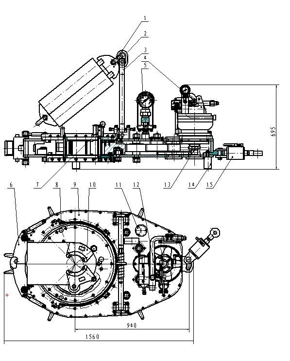
As seen in FIGS. 1 and 2, the power tong 6 may include three main sections mounted on a common axis A; namely a main drive section, a rotor, and a back-up jaw. Each of the sections contains actuators, as better described below. The main drive section 10 which provides at least part of a rigid stationary framework or stator frame is located above the rotor 22. The backup jaw 48, located below rotor 22, may also provide part of the stator frame. The rotor 22 rotates relative to the main drive and back-up jaw. Both the rotor and backup jaw clamp their respective sections of pipe. The rotor 22 is rotated by the main drive section 10 independently of the main drive section and backup jaw in the sense that the rotor 22 is self-contained, having on-board hydraulic and electric power generators to power on-board radial clamps or grippers (collectively herein referred to as grippers), and an on-board serpentine secondary power transmission, all configured to allow the insertion and removal of a pipe through a jaw opening from or into the center of the jaw, so that the pipe, when in the center of the jaw may be clamped, torqued, and spun about axis A of rotation of the rotor 22 while the other, oppositely disposed section of pipe is held clamped in the center of the back-up jaw 48.
As shown in FIGS. 1, 2 and 3 rotor 22 is housed within drive section 10, although this is not intended to be limiting as the rotor may be mounted so as not to be housed within the drive section and still work. The rotor 22 is cylindrical in shape and has an opening slot, which although illustrated as linear may be linear or non-linear, having a throat 38 for passing of a tubular along the slot thereby allowing the tong axis of rotation A to be selectively positioned concentric with pipe 8, provided the rotor 22 is rotated such that its throat 38 is aligned with the front openings 28 and 29 of the main drive section and back-up jaw, respectively. Center 40 of the yoke formed by the jaw and slot corresponds with axis A. The rotary jaw 22 has three gripper cylinders 44 a, 44 b, and 44 carranged radially, with approximately equal angular spacing around axis A, mounted between the two parallel horizontal planes containing rotor gears 30 aand 30 b. The number of gripper actuators, such as gripper cylinders 44 a-44 c, and associated grips or grippers may be more or less in number, so long as a tubular joint may be gripped or clamped at center opening 40.
A serpentine member such as serpentine drive belt 20 is driven by two serpentine drive motors 18, which may for example be hydraulic or electric motors. The serpentine member is mounted around so as to engage stator sprockets mounted on the stator frame. For example the stator sprockets may include drive sprockets 26 awhich are driven by serpentine drive belt 20 to collectively provide a secondary drive powering the grippers on the rotor 22. Drive sprockets 26 arotate serpentine drive belt 20 about idler sprockets 26 mounted to drive section 10. And the serpentine drive belt 20 also engages about rotor sprockets 32 a-32 fmounted on the rotor 22 as better described below. The rotor sprockets 32 aand 32 bmay be two generator drive sprockets. The rotor sprockets 32 cand 32 dmay be two pump drive sprockets. Rotor sprockets 32 eand 32 fmay be two idler sprockets. In the illustrated embodiment, which is not intended to be limiting as other embodiments discussed below would also work, the generator drive sprockets, that is, rotor sprockets 32 aand 32 b, transmit rotary power to generators 34. The pump drive sprockets, that is, rotor sprockets 32 cand 32 d, transmit rotary power to hydraulic pumps 36 by the action of serpentine drive belt 20 engaging the upper groove of rotor sprockets 32 a, 32 b, 32 cand 32 d. A synchronization belt, 28 a, connects the lower portions of the rotor sprockets 32 a-32 f. Thus as the rotor 22 rotates on axis of rotation A, even though serpentine drive belt 20 cannot extend across the throat 38 because such a blockage would restrict selective positioning of the pipe 8 along the slot into the tong, serpentine drive belt 20 wraps in a C-shape around the rotor sprockets 32 a-32 f. Serpentine drive belt 20, driven by drive sprockets 26 a, runs on pulleys 26, and on idler sprockets 26 band 26 cmounted to, so as depend downwardly from, main drive section 10. The extent of the C-shape of serpentine drive belt 20 provides for continual contact between serpentine drive belt 20 and, in this embodiment which is not intended to be limiting, a minimum of three of the rotor sprockets 32 a-32 fas the rotor rotates relative to the main drive section 10. The synchronization belt 28 amounted on the rotor maintains rotation of the individual rotor sprockets as they pass through the serpentine gap 29 seen in FIG. 4, that is, the opening between sprockets 26 band 26 c. Synchronization belt 28 asynchronizes the speed and phase of the rotation of each of the rotor sprockets 32 a-32 fto allow each of them in turn to re-engage the serpentine drive belt 20 after they are rotated across the serpentine gap 29 by the action of the rotor rotating relative to the main drive.
During operation of tong 6 the secondary drive (drive motors 18) and serpentine drive belt 20 run continuously to deliver power to the on-board pumps and generators by means of the rotor sprockets 32 a-32 d. Rotation of the rotor 22 by the operation of the primary drive acting on the pinions 56 and rotor gears 30 aand 30 bdoes not substantially affect the powering of the on-board accessories (pumps and generators) because drive belt 20 is run at substantially an order of magnitude greater speed than the speed of rotation of rotor 22. The rotation of the rotor only adds or subtracts a small amount of speed to the rotation of the rotor sprockets.
Upper rotor gear 30 aand lower rotor gear 30 bare parallel and vertically spaced apart so as to carry therebetween hydraulic pumps 36, generators 34, the rotor hydraulic system, rotor jaw electrical controls and the array of three radially disposed hydraulic gripper cylinders 44 a, 44 b, and 44 c, all of which are mounted between the upper and lower rotor gears 30 aand 30 bfor rotation as part of rotor 22 without the requirement of external power lines or hydraulic lines or the like. Thus all of these actuating accessories, which are not intended to be limiting, may be carried in the rotor 22 and powered via a nested transmission, nested in the sense that the C-shaped synchronization drive loop mounted on the rotor, exemplified by synchronization belt 28 a, is nested within so as to cooperate with the C-shaped serpentine drive loop mounted to the main drive, exemplified by serpentine drive belt 20.
Thus as used herein, a serpentine belt, such as the serpentine belt 20, driving a plurality of stator and rotor sprockets (as herein below defined), and as in the various forms of the stator and rotor sprockets found illustrated in all the figures herein, are herein referred to generically as a form of nested transmission. The nested transmission transfers power from the fixed stage to the rotational stage in a continuous fashion as, sequentially, one element after another of the rotational drive elements on the rotating stage are rotated through and across throat 38 and gap 29 allowing selective access of the tubular 8 to the center opening 40 of the stage.
For proper operation of the tong, it is desirable that the gripper actuators such as gripper cylinders 44 a-44 cclamp the tubular 8 substantially at, that is, at or near the rotational center axis of the tong. It can be readily seen that gripping the tubular 8 with a significant offset from the center axis would result in wobble or runout of the tubular when spinning in or out and could result in thread damage, excessive vibration, damage to the machine and inaccurate torque application.
It will be appreciated that the inboard ends of side gripper cylinders 44 aand 44 bmove in an arc as the gripper cylinders are extended or retracted. For the side gripper cylinders 44 aand 44 b, the geometry of reaction links 44 eis optimized to minimize deviation from the nominal gripper cylinder radial axis over the gripping diameter range to angles typically less than one degree. The gripper cylinders 44 aand 44 bwill however swing significantly from the nominal gripper cylinder radial axis, in the order of five degrees, when they fully retract to clear the throat 38. It is an advantage of the link design that it requires less stroke to clear the throat 38 due to the swing associated with the arc of reaction links 44 e, which ultimately allows a more compact rotor and hence a more compact tong. That is, the combination of the swing in direction C with the retracting stroke in direction D results in less of a stroke length required to clear throat 38 than merely using a retraction stroke without swing. The amount of swing is governed by the radius of arc E associated with rotation of the reaction links 44 eand the length of the required stroke in direction D.
The back-up jaw section 24 as shown in FIGS. 5, 5 a, 6 and 8 is typically mounted to a tong positioning system capable of holding the tong assembly level and enabling vertical and horizontal positioning travel. The tong may be pedestal-mounted on the rig floor, mast-mounted, track-mounted on the rig floor or free hanging from the mast structure. It may also be mounted at an angle for slant drilling application or with the pipe axis horizontal.
The back-up jaw section 24 includes a parallel spaced apart array of planar jaw frames and in particular an upper backup jaw plate 48 aand a lower backup jaw plate 48 b. Backup jaw plates 48 aand 48 bmay be maintained in their parallel spaced apart aspect by structural members 48 c. Thread compensator cylinders 50 actuate so as to extend bolts 46 on rods 50 ain direction F so as to selectively adjust the vertical spacing between the rotor section 23 and the backup jaw section 24. Thus with the cylindrical threaded joint 8 aof tubular 8 held within cylinders 52 a-52 cin the backup jaw section 24 (that is with joint 8 aheld lower than shown in FIG. 3 so as to be clamped between the cylinders 52 a-52 cof the back-up jaw section 24), and as seen in FIG. 1 with threaded tapered female end or box opening upwardly in the joint 8 aheld within cylinders 52 a-52 c, as the rotor 22 is rotated relative to the fixed back-up jaw section 24 so as to rotate the box relative to the opposed facing pin, the rotor 22 and back-up jaw 48 may be drawn towards one another by the retraction of rods 50 ainto thread compensator cylinders 50 in direction F or alternately, separated from on another by the extension of rods 50 afrom cylinders 50. This action serves to compensate for the axial thread advance of the tubular as it is screwed in or out and avoids excessive axial forces on the tubular threads. The combined upward force exerted by thread compensator is controlled via the hydraulic pressure to approximately equal the weight of the upper tubular. Thus a further advantage of the invention is a reduction of tubular thread wear because the threads are “unweighted” when spinning in or out. The spacing between the back-up jaw plates 48 aand 48 bdefines a cavity in which is mounted the array of hydraulic gripper cylinders 52 a, 52 band 52 cpositioned radially about axis A and in approximately equal angular spacing. Hydraulic cylinders 52 a-52 care disposed radially inward in an arrangement corresponding to that of cylinders 44 a-44 cso that the operative ends of the cylinders 52 a-52 cwhich may be selectively actuated telescopically into the center opening 40 of the yoke so as to clamp therein a tubular 8 and in particular a lower portion of a tubular joint while an upper portion of the tubular joint is clamped within cylinders 44 a-44 cand rotated in rotary jaw section 23 in direction B about axis of rotation A relative to the fixed main drive section 10 and back-up jaw section 24.
As shown in FIG. 1, the rotor 22 is maintained in alignment with axis of rotation A by means of upper and lower guide bearings 54 aand 54 brespectively. The top of the rotor 22 has a cylindrical race 54 cbolted to the top surface. Race 54 cslides within upper guide bearing 54 afixed to the top plate of frame 60. Similarly, the bottom surface of lower rotor gear 30 bis profiled to create a race which slides within lower guide bearing 54 bfixed to the lower plate of frame 60. The upper and lower bearing rings are interrupted, that is do not complete a full circle, so as to match the opening of throat 38 of the frame. Another guide method may include guide rollers which are rotatably mounted in a array circumferentially around the outer circumference of the rotor with their rotational axis parallel to rotation axis A. In the present embodiment, upper and lower guide bearings 54 aand 54 bcentralize the rotor 22 along rotational axis A and ensure proper meshing of the rotor gears 30 aand 30 bwith the drive pinions 56.
The drive pinions 56, a minimum two but ideally four, are arranged circumferentially around the rotor 22 and intermesh and engage helical teeth with corresponding rotor gear teeth on the outer circumference of rotor gears 30 aand 30 bso that as drive pinions 56 are driven by main drive hydraulic motors 16 via gear reduction devices 16 arotor gears 30 aand 30 bare simultaneously rotatably driven (in either direction) about axis of rotation A. Pinions 56 and the corresponding rotor gear teeth are helical. Each drive pinion 56 has its rotational axis parallel to axis A and consists of an upper pinion 56 aand a lower pinion 56 b. The helix angles of the upper rotor gear 30 aand lower rotor gear 30 bare equal and opposite to ensure proper meshing torque splitting between top and bottom rotor gears. The rotor 22 is mounted within a-frame 60, wherein frame 60 may be a frame or housing. The primary drives 12 and driver 18 are mounted on top of frame 60, and back-up jaw section 24 is mounted beneath frame 60.
In the preferred embodiment, as seen in FIG. 10, the rotor hydraulic system 53 is a dual (high/low) pressure system or infinitely variable pressure system which produces high pressures (in the order of 10,000 psi) necessary for adequately gripping large and heavy-duty tubulars and for applying make-up or break-out torque, and lower pressures (2500 psi or less) to avoid crushing smaller or lighter-duty tubulars. Hydraulic pumps 36, rotationally driven as described above, are fixed-displacement, gear or variable displacement piston pumps. In the idle state, hydraulic pumps 36 charge one or more gas-filled accumulators 55 mounted in or on rotor 22 to store energy to enable rapid extension of the gripper cylinders 44 a-44 c. In this way, very fast gripping speeds may be achieved while keeping the power transmitted by the serpentine drive belt 20 drive low. That is, although the power supplied via the serpentine drive belt is small, the rotor hydraulic system must be able to intermittently supply a relatively large flowrate at low pressure for rapid advance of the gripper cylinders until they contact the tubular and also supply a low flowrate at very high pressure, in the order of 10,000 psi, to adequately grip the tubular for torquing operations.
In the schematic of the preferred rotor hydraulic system 53 of FIG. 10, system 53 has one or two gear or piston pumps 36 of relatively small capacity, within the power limitations of the serpentine drive belt. When there is no gripping demand, the pumps charge one or more gas-filled accumulators 55 to store energy for intermittent peak demands. The accumulators are optional, for the benefit of advance speed. The system is workable without accumulators provided the pumps are variable displacement. A load-sensing circuit with or without regenerative advance may also be used as would be understood by someone skilled in the art. A directional control valve 63 directs hydraulic pressure to the gripper cylinders. The directional control valve is solenoid-actuated with the solenoids controlled by the rotor control system. There are two flow paths from the directional control valve 63 to the extend side of the gripper cylinders. The first is the rapid-advance flow path which directs a large flowrate, in the order of thirty-five gallons per minute, from the pump(s) 36 and accumulator(s) 55 to the gripper cylinders at relatively low pressure, in the order of 2500 psi, for rapid extension of the gripper cylinders until they contact the tubular 8. The second is the high-pressure path in which pressure is regulated by a proportional pressure control valve 64 which is controlled by the rotary jaw control system of FIG. 11. The regulated pressure is supplied to an intensifier 65 which boosts the pressure by a factor in the order of 4:1 to supply high pressure, in the order of 10,000 psi, to the gripper cylinders. A check valve 66 prevents the high pressure fluid from flowing back into the rapid-advance low pressure flow path. The directional control valve 63 can also be solenoid actuated to direct fluid to the rod side of the gripper cylinders for retraction.
The use of high grip pressures, in the order of 10,000 psi, allows the use of compact gripper cylinders which results in a compact tong. By using the intensifier 65 to build the high grip pressure, no high pressure control valves are required.
It can be seen that in spite of the small input power, the hydraulic system can intermittently supply large flowrates for rapid grip cylinder advance and high pressures for high-torque operations. The system can regulate the grip pressure, adapting to the applied torque, for optimum gripping performance.
The rotor control system seen in FIG. 11 activates and de-activates the gripper cylinders at the operator"s discretion, regulates grip pressure and monitors system function without any power supply or control wires from or to the fixed part of the tong, because the rotor is fully rotatable and the open throat of the yoke precludes the use of any slip rings which are commonly used to transmit electrical power and control signals to a rotating element.
As seen in FIG. 11, one or two generators 34 are driven by the serpentine belt drive 20. They supply power, preferably 24 volts DC, to a programmable logic controller (PLC) 70, a radio communication link 71 and a number of sensors 73.
The radio communication link 71, which may advantageously be a Bluetooth™ device, communicates wirelessly with a similar radio communication link 72 mounted on the stationary section of the tong. The two radio communication links, 71 and 72, act as a wireless communication bridge between the main tong control system 74 and the rotor PLC 70.
The rotor PLC 70, as directed by the main tong control PLC 74, controls the output solenoids on directional control valve 63 to extend and retract the gripper cylinders 44 a-44 cand the proportional pressure control valve 64 to control the grip pressure. It also receives feedback from sensors 73 on the rotor for such parameters as (possibly including but not limited to) grip pressure, hydraulic pump pressures, grip position and hydraulic oil temperature.
In the present invention, the rotor 22, frame 60, and primary drives 12 are rotationally independent of the backup jaw section 24. As shown in FIG. 6 the rotor 22 is axially supported by the thread compensator cylinders 50 which are mounted with spherical bushings 82 at both ends so that they do not react any torque between the frame 60 and the back-up jaw section 24.
Frame torque is reacted to the backup jaw section 24 via two reaction beams 83 mounted in the backup jaw section 24 and with their top ends connected to the frame 60 via spherical bearings 84. The reaction beams 83 are free to slide vertically relative to the backup jaw section 24 in guide bushings 84 to allow for thread advance compensation travel. Guide bushings 84 restrain the reaction beams 83 laterally so that they are effectively cantilevered upward from the backup jaw section 24. The torque of the rotary jaw frame 60 is reacted at the top of the reaction beams 83.
When breaking out (unscrewing) drilling tubulars, it is often difficult to identify the axial location of the split where the two tool joints meet. It is imperative that the tong be positioned such that the split is located in the axial gap between the rotor grippers and the back-up jaw grippers. If either the rotor or the backup jaw grips across the split, the tool joint and the tong may be damaged and time will be wasted because the connection will not break out.
As shown in FIGS. 15 and 16, the actual face seam 200 between the mating connection shoulder faces 201 is only marginally visible when the connection is made up and it may be further obscured by drilling fluid. There is typically a shoulder bevel 202 adjacent to each shoulder face 201. The shoulder bevel 202 is typically machined at a 45 degree angle and has a radial dimension typically 2 to 6 mm. The two adjoining shoulder bevels 202 combine to form a connection split bevel V-groove 203. The connection split bevel V-groove 203 is usually sufficiently visible to identify the split axial location for placement of manual tongs in conventional drilling operations. But for a mechanized tong with its operator positioned several feet away from the pipe, it may be difficult to see. Furthermore, the tong may obscure the operator"s direct view of the split location. Time will be wasted in identifying the split location, traveling to it and verifying that the split is correctly located in the axial gap between the rotary and back-up jaws.
It can be seen that a reliable automated system to detect the location of the connection split would improve speed and efficiency of a mechanized tong and is mandatory for fully-automated tong operations.
A tandem configuration may be employed. That is, the optical tubular caliper can be accomplished with a pair of single point beam sensors positioned approximately 180 degrees apart, with each beam projected radially inward toward the tubular at the same elevation. Each sensor measures the radial distance to the pipe surface. The control system computes the sum of these distances. The difference between a fixed offset value and the computed sum represents the diameter of the tubular, approximately independent of the position of the tubular in the opening. The system can quickly and accurately measure the diameter of any tubular passing through the single point beams and transmit the diameter measurement to the tong control system. Furthermore, as the tong travels axially along the pipe, the tong control system can relate a series of such diameter measurements to the corresponding tong elevations as measured via the control system instrumentation described elsewhere. A diameter profile along the length can thus be created, effectively a virtual diameter versus axial position plot. The control system can compare this diameter profile to the known characteristic of the connection split bevel V-groove 203. When such a profile match is identified, the connection split is located and the corresponding tong elevation is recorded. The tong then travels the contact axial offset distance between the light band 705 axial mounting position and the desired split position between the rotary and back-up jaw grippers.
The control system is programmed to tune out irrelevant variations in the measured outside diameter, such as at the tool joint upset steps. It will also filter out diametral noise associated with surface irregularities such as hardbanding, tong marks or wear grooves.
As mentioned above, the power tong according to the present invention may be mounted in many ways on the drilling rig structure, or it may also be free-hanging from a cable. The mounting method ideally allows the tong to be accurately positioned around the tubular 8 at a large range of elevations, retracts a substantial distance from well center for clearance for other well operations, parks in a small area to minimize space usage on the drilling rig floor, keeps the tong level and allows the tong to be positioned to work at multiple locations such as the mousehole which may not be in the same plane as well center and the tong park location. The mounting system could be capable of rapid movement between working and idle positions but with smooth, stable motions. It should allow the operator to command horizontal or vertical movements or a combination.
Numerous tong or wrench mounting mechanisms exist in the industry. Most are Cartesian (horizontal/vertical) manipulators employing tracks, slides or parallelogram linkages for each motion axis. These mechanisms are simple to control because they directly actuate on the horizontal and vertical axes but they typically have a small range of motion which limits tong functionality and restricts mounting location on the drill floor. They have a large parked footprint which consumes scarce rig floor space and interferes with other well operations. And they have little or no capability to react torque applied to the tong or wrench by a top drive in the rig.
Thus in one preferred embodiment, a tong is preferably mounted on a manipulator 99 as shown in FIGS. 12aand 12b. A slewing base 100 is mounted to the drilling rig floor. A hydraulic slewing motor 101, via a gear reduction, can turn the slewing base up to three hundred and sixty degrees about the vertical axis. The internal bearings of the slewing base can support the weight and overturning moments of the manipulator structure and the tong. Slewing motor 101 may alternatively be electric, pneumatic or manually actuated.
A second boom, boom 103, is pivotally mounted at the top of boom 102. The angle of boom 103 relative to boom 102 is controlled by linear actuator(s) 105. The inclination on boom 103 is monitored by angle sensor 108.
The tong is pivotally mounted at the end of boom 103. The angle of the tong relative to boom 103 is controlled by linear actuator(s) 106. The inclination of the tong is monitored by angle sensor 109.
Various possible tong positions are selectively positioned between the extended operating position illustrated in FIG. 12aand the parked position of FIG. 12b. It can be seen that the manipulator 99 provides a large range of motion but can park the tong 6 with a small footprint.
The booms have significant lateral and torsional stiffness. This is advantageous over prior systems because the structure can react torque applied to the tong by a top drive in the rig, such as for back-up of drilling connection make-up. The tong can also apply torque to make up a bit restrained in the rig"s rotary table.
Manipulator 99 may be fully functional with manual controls for each of the four output actuators (slewing motor 101 and linear actuators 104, 105 and 106). However, it preferably has a control system as described below in which horizontal and vertical rates of tong travel are controlled in direct proportion to horizontal and vertical velocity commands by the operator and the tong is automatically kept level. The control system may also include the capability of optimized travel, including acceleration and deceleration control, to pre-defined locations.
The tong"s vertical and radial positions (relative to the slewing base) at any time are computed by the programmable logic control (PLC) 112 geometric constants and the boom 102 and 103 angles measured by angle sensors 107 and 108. The slewing orientation is measured preferably by an encoder 110 on the slewing drive. The tong"s three-dimensional position is therefore monitored at all times.
The preferred operators control console has a single 3-axis joystick 111 for control of the manipulator. The x-axis of joystick 111 controls the horizontal motions of the tong, the y-axis of the joystick 111 controls the vertical motions of the tong and the z-axis (handle twist) of the joystick controls the slewing motions of the assembly. The joystick commands may be discrete ON/OFF but are preferably analog/proportional on the x and y axes for finer control.
Horizontal motion of the tong requires movement of both boom 102 and boom 103, accomplished via linear actuators 104 and 105. The required output velocity signals to each of linear actuators 104 and 105 are computed in the PLC 112 in order to achieve the desired horizontal command velocity from the x-axis of joystick 111.
Similarly, vertical motion of the tong requires movement of both boom 102 and boom 103, accomplished via linear actuators 104 and 105. The required output velocity signals to each of linear actuators 104 and 105 are computed in the PLC 112 in order to achieve the desired vertical command velocity from the y-axis of joystick 111.
In particular, in FIG. 18, serpentine drive belt 20′ is driven by at least one serpentine drive motor which may for example be at least one hydraulic motor. The serpentine drive motor drives at least one drive sprocket 26 a′ which, as before, provide a secondary drive via a plurality of rotor or satellite sprockets 32′ on rotor 22, and also drives a synchronizer between sprockets 32′ and a coupling such as pumps or generators, or a mechanical mechanism powering gripper actuators and corresponding grippers 44′, or directly acting on grippers 44′, on the rotor 22. As illustrated by way of example, a first drive stator sprocket 26 a′ rotates serpentine drive belt 20′ about a second stator sprocket which may be a second drive sprocket 26 a′ or an idler sprocket 26′ mounted to drive section 10. A tensioner 27 such as a tensioning idler sprocket, which may be considered a third stator sprocket, may be mounted to frame 60 so as to be resiliently biased against serpentine drive belt 20′ to tension the drive belt. A pair of satellite or rotor sprockets 32′ are mounted on the rotor 22. As seen in FIG. 18, the first and second stator sprockets are mounted on substantially opposite sides of the rotor. As the term is used herein, the first and second stator sprockets are arrayed substantially around the rotor. Third, fourth, etc stator sprockets would thus not have to be on one side or the other of the rotor, but would form part of the array of stator sprockets arrayed substantially around the rotor.
Synchronization belt 28 a′ is, as before, mounted on rotor 22 and passes around satellite or rotor sprockets 32′ and idler sprockets 33′ so as to maintain rotation of the individual rotor sprockets 32′ as they pass sequentially through the serpentine gap 29 (such as seen in FIG. 4). Synchronization belt 28 a′ synchronizes the speed and phase of the rotation of each of the rotor sprockets 32′ to allow each of them in turn to re-engage the serpentine drive belt 20′ after they are rotated on rotor 22 out of contact with drive belt 20′ across the gap between drive sprockets 26 a′ by the action of rotor 22 rotating relative to the frame on which the main drive is mounted, ie the main drive section 10.
The rotor sprockets 32′ drive for example one or more on-board generators and/or one or more on-board hydraulic pumps (not shown in FIGS. 18 and 19). Synchronization belt 28 a′ may connect the lower or upper portions of the rotor sprockets 32′, with the serpentine drive belt 20′ then connecting the upper or lower portions of the rotor sprockets 32′ respectively. Thus as rotor 22 rotates about axis of rotation A even though serpentine drive belt 20′ cannot extend across the opening throat 38 because such a blockage would restrict selective positioning of the pipe 8 along the slot into the tong, serpentine drive belt 20′ wraps around or reaves so as to remain at all times in contact with at least one of rotor sprockets 32′. Drive sprockets 26 a′ are mounted to, so as to for example depend downwardly from, main drive section 10. As seen in FIG. 18a, the deflection of serpentine drive belt 20′ by the rotation of rotor sprockets 32′ provides for continual contact between serpentine drive belt 20′ and a minimum of one of the rotor sprockets as the rotor 22 rotates relative to the main drive section 10, wherein the deflection of serpentine drive belt 20′ tensions the portion of drive belt 20′ where it contacts tensioner 27. Upon return of the rotor sprockets to the position of FIG. 18, tensioner 27 takes up the slack in the drive belt 20′.
The forms of coupling are also not intended to be limited to only those illustrated or discussed elsewhere herein, as for example the coupling may include a mechanical coupling or linkage between the rotor sprockets and grippers. For example, the rotor sprockets may directly or indirectly drive worm gear reducers which drive screws which grip pipe 8, in which case the serpentine, such as drive belt 20′, would operate to directly cause the screws to clamp or unclamp the tubular. The screws when tightening on to a tubular would, for example, be turned until they come to a stop against the tubular joint, at which time the serpentine would stop turning as the serpentine drive stalls and thereafter would turn to match the rotation of the rotor in either direction to maintain approximately constant tension on the serpentine drive belt.
As seen in FIG. 19a, rotor 22, the rotor sprockets 32′, and one or more energy coupling 45 may be mounted within a rotary jaw frame 47 on, for example, bushings 49. Energy couplings 45 couple the energy being transmitted from the serpentine to the rotor sprockets 32′, and couples the energy to the grippers 44′ or gripper actuators (which in turn actuate the grippers). As stated above, energy couplings 45 may include pumps, generators, or mechanical drives such as direct mechanical linkages, but may also include the use of energy storage such as, without intending to be limiting, gas accumulators, batteries, capacitors, flywheels, which may then power actuation of the grippers when needed.

In assembling a string of tubing for an oil well, a long series of pipe sections are screwed together, usually by means of a power tongs. Conventional power tongs have jaws with serrated faces that are designed to bite into the pipe surface. These jaws are usually cam operated, so that their closing force is roughly proportional to the tongs torque. Such an arrangement, however, is unsuitable for certain modern tube materials which are particularly soft. This is true for example, for some high chromium pipes designed for corrosion resistance rather than strength, and for fiber glass tubing now being developed. There are also pipes having protective coatings designed to protect the underlying material from corrosion by hydrogen sulfide and other subterranean chemicals. Some tubing costs on the order of one thousand dollars per foot, and a string is typically thousands of feet long. Plainly, it is critical not to damage tubing while making up a string, and to avoid any surface damage that could reduce service life.
Consequently, there is a need for power tongs whose jaws will not injure the surface of tubing and yet can deliver to the tubing adequate torque, which may be several thousands foot-pounds. The approach taken by this invention is to provide jaws actuated by hydraulic linear motors so that jaw pressure can be accurately controlled.
Hydraulically biased jaws on power tongs are known in the prior art; see, for example, U.S. Pat. Nos. 3,796,418, 3,921,473, 4,057,887 and No. 4,402,293. None of these however, provide means for independently controlling the jaw force.
It is therefore an object of this invention to construct a power tongs having jaws designed not to bite into the surface of pipe or tubing and yet able to transfer sufficient torque to the tubing.
Another object is to control jaw pressure independent of tongs torque. These and other objects will be apparent from the following description of a preferred embodiment of the invention.
The foregoing objects are met, according to this invention, by a power tongs having at least one hydraulically biased jaw, and means for controlling the hydraulic pressure delivered to the jaw. With this arrangement, smooth-faced jaws made of soft material can be used, and purely frictional engagement with the pipe surface suffices to make up the string.
As shown in FIGS. 1 and 2, an apparatus embodying the invention comprises a power tongs 10 including a motor 12 driven by hydraulic fluid or other medium. Means (not shown) are provided for manually or automatically controlling the tongs motor. The tongs motor 12 is connected through gearing, not shown, to a rotary head 14, to which the pipe gripping assembly 20 of the invention is attached. The gripping assembly comprises plural (preferably three) segments 22a, 22b, 22c equally spaced around a vertical axis corresponding to that of a pipe P that is to be torqued.
In operation, the tongs are brought, laterally, over a pipe joint P, FIG. 1, and the gripping assembly 20 is closed around the pipe by means of the latch 26. Air pressure from source 42 is then applied via fitting 44, whereupon the pump 46 generates hydraulic pressure within the cylinders 32, which pressure is limited by the setting of the pressure relief valve 52. The check valve 50 maintains the cylinder pressure after the air source is disconnected, whereafter there are no external hoses or other connections to the gripping device that would prevent it from rotating. The tongs are then activated, causing the gripping device and the pipe P to rotate with the rotary head until the desired torque is reached. Various torque limiters, such as those disclosed in U.S. Pat. Nos. 4,552,041 and 4,579,024, may be used to control the tongs, if desired.
To release the pipe P, the valve 54 is opened, allowing the pistons 34 to be retracted by their biasing springs as fluid escapes to the reservoir 48. The device may then be unlatched, and the tongs are then removed from the pipe.
The adjustability of the relief valve 52 enables one to control the actual clamping jaw force, independently of tongs torque. It is therefore possible, with this invention, to avoid excessive clamping pressures that could cause surface or structural damage to soft pipes. The service life of some of the most expensive tubing can thus be markedly prolonged. The pressure reaching cylinders 32 is limited by means of the adjustable pressure relief valve 52, which is set to a pressure that is a function of pipe material, size, makeup torque and possibly other factors. The upper pressure limit, for a given size jaw, is necessarily that pressure which would collapse or crush the pipe. However, the jaws may be made as long as desired; e.g., one foot long or more, so as to distribute jaw load over a greater surface area. As a result, by judicious design choice, any desired torque can be transferred to the pipe by the gripping assembly, without damaging the pipe surface.
With this invention, jaw forces are positively controlled and limitied, without regard to the tongs torque. This is in complete contrast to traditional cam-operated jaws, where jaw force is roughly proportional to tongs torque and is usually unknown in magnitude.
Various other modifications will occur to those of skill in the art, to create other uses for the invention. For example, the gripping device could be used in a (non-rotary) backup tongs. Also, high pressure water could be used in place of hydraulic fluid to drive the pistons 34, and such a modification would avoid the release of oil into the environment.
The present invention relates to oil field devices. More particularly, the present invention relates to an apparatus which has the ability to position and properly align a power tong around sections of oil field pipe on the rig floor by a single deck hand.
In the drilling and completion phases in exploring for oil and gas, pipe tongs have been utilized for engaging lengths of drill or completion pipe, known generally as tubular members, end to end, by deck hands on the rig floor. A typical power tong comprises a first set of jaws which hold one section of pipe stationary while a second set of jaws rotate the next section to make up or break up the joint. The power tongs may weigh a few thousand pounds and are usually supported from the rig by a cable that allows the power tong to be moved manually by the deck hands to engage the pipe, or disengage from the pipe, and be positioned away from the pipe string, to allow other work to proceed. Interconnected by a hydraulic cylinder, often referred to as a ‘lift’ cylinder, the power tong is connected on the one end to the rig cable and to the other end there attached to the power tong. The hydraulic cylinder allows the Power Tong Operator, from the operator"s position at the Power Tong, to make Vertical corrections, both upwardly and downwardly to the Power Tong for positioning on the make or break out of the pipe. Such a lift system is illustrated in FIG. 19, labeled “Prior Art” is well known in the art.
However, because of the size of the power tongs, more than a single individual, often times two or three men, are required to move the tong into position, and operate the tong to make up or break the joint, and then to manually swing the tong, hanging from the cable, out of the way, and engage it in a position away from the pipe, so that the deck hands can proceed to other chores. This manual operation of the tong in and out of position must be done with care, since the tong, swinging free from the cable, may strike one of the workers, or inadvertently disengage from its position and injure workers or damage materials on the rig floor. Typically there are two types or composition of pipe or tubulars screwed together one piece to another, end to end, until the entire number of sections of pipe required for the job are joined together and run into the ground below the rig floor. One composition of pipe is steel pipe which may be screwed together without much care taken by the deck hand and/or the type of handling tool and power tongs to be used. However, another composition of pipe utilized for this type work is Chrome 13 or similar soft composition which requires much care when screwing one pipe section to another section requiring the Power Tong to be carefully placed on each section to prevent damage to the external coating of each pipe section. As the Power Tong comes in contact with each Chrome pipe section, care must be taken not to have damaging contact which may result in rapid deterioration once exposed to a harsh environment down hole. The difficulty in operating power tongs in this fashion has led to attempts to provide a different system to utilize and maneuver power tongs on the rig floor.
For example, U.S. Pat. No. 6,318,214 entitled “Tong Positioning Apparatus,” discloses a power tong support apparatus having a frame, and a base movably positioned on the frame, with the power tong support attached to the base and movable to and away from the power tong. However, one of the drawbacks to this device is that the device requires a rather large and cumbersome frame to support the tong support member, which is not desirable because of the scarcity of rig space. Further, the device does not appear to allow the tong support member to operate at variable heights from the rig floor, which is necessary, since the pipe sections may be connected and disconnected at various heights above the rig floor.
The present invention solved the problems in the art in a simple and straight forward manner. What is provided is an improved tong positioning and alignment apparatus which includes a base with a drip pan, designed to capture accidental oil spill or drip from the system, positionable on the rig floor; a hydraulic cylinder positioned on the base, having a first end engageable to a rear support member and a second end engageable to a pivotal moment arm; a forward shock attachment arm(s) engaged at a first end to one of three attachment points on the moment arm, and a second end which attaches to a tong frame attachment point(s) on the tong. The (single) moment arm may be bilaterally functional provided the system has a pivotal shaft extending outwardly on each side of the forward support member whereby the forward end of the moment arm actually has two forward ends, one each on each side of the forward support member and each having multiple bores thus emanating the structure for an additional forward shock absorber attached thereof.
Further, the tong frame is designed with a forward tong frame pivotal attachment member to accommodate a forward shock absorber on each side which additionally provides greater strength and stability during the torque process and further limits the bending and shearing effect of the tong while in tension with the tubular section. The greater the stress established through the bending and shearing effect applied to the threaded connection, the greater the probability the torque turn graph may display a bad connection thus the potential to discard that particular threaded section. Each forward shock attachment arm includes a pair of shock absorbers engaged along its length to provide a smooth, non-jerking motion both vertically and horizontally in moving the power tong. Each forward shock attachment arm may also be designed with more than two shock absorbers or the use of only one single shock absorber is desirable if the handling procedure with the size and weight of each power tong thus dictates the need for such. The tong positioning apparatus is designed to be remotely operated by hydraulic, air, air over hydraulics, electronically, hard wired or wireless or otherwise by a single operator. There is further provided a plurality of attachment points on the rear support member, and a plurality of pivot points for the moment arm, to allow for various vertical and horizontal positioning of the tong during makeup and breakup of pipe on the rig floor. Further, the apparatus includes a safety shield system to insure the workers are protected from inadvertent contact with moving parts of the apparatus.
Further there is provided a means for aligning the pipe within the tong apparatus by so that pipe, such as Chrome 13, or similar soft pipe, can be carefully guided into the tong, and eased in position, without the pipe wall making forceful contact with the tong. There is further provided at least two cameras which view the entire operation so that the manipulation of the pipe can be accomplished by an operator from a remote location.
Therefore, it is a principal object of the present invention to provide an improved tong positioning and further to provide an alignment apparatus which insures a safe working environment and saves time, promotes efficiency and reduces fatigue while operating power tongs on a rig.
It is a further principal object of the present invention to provide a tong positioning and alignment apparatus which requires a minimum of rig space, is able to be operated by a single deck hand through a power system operated at the location of the power tong operations or remotely operated from any location on the rig floor.
It is a further object of the present invention to provide a tong positioning and alignment apparatus wherein a hydraulic cylinder or air cylinder, hydraulic motor, chain or belt drive, cam over action or otherwise any driver when activated, operates a moment arm, pivotally attached to a forward support member, which is attached through a shock absorbing member downward or otherwise vertically, upwardly or downwardly, or horizontally to a forward pivotal support member on the power tong frame to allow forward and rearward movement of the power tong at various heights above the rig floor.
It is a further object of the present invention to provide a tong positioning and alignment apparatus engineered to provide strength and stability to contain the predetermined rotational force of the tong and prevent potentially serious injury to any deck crew member should the snub line fail or be improperly adjusted. It is well known in the art that great torque is applied to the pipe by the upper tong jaws as the lower tong jaws hold the pipe in place. With such great torque applied to the pipe section presents the possibility of malfunction of the lower tong jaw which restrains the pipe while the upper tong jaw is making up the threaded connection to the desired torque value. Should the lower jaw fail and the upper tong continues its predetermined rotational path, the present invention is designed to contain and prevent said rotational path of the upper tong and further prevent possible serious injury or death to the rig crew members.
It is a further object of the present invention to provide a tong positioning and alignment system which includes a protective frame and cover which can be retracted in and out of position when necessary.
It is a further object of the present invention to provide a tong positioning device which incorporates a shock absorber system to allow the jaws of the device to contact soft pipe, such as chrome pipe, without damaging the wall of the pipe.
It is a further object of the present invention to provide a tong positioning and alignment device which incorporates a tubular guide plate on the tong but preferably attached on the hydraulic back-up, or lower tong, to allow the soft pipe, such as chrome pipe, to be gently guided into the open throat of the tong and further to the tong jaws without damaging the wall of the pipe.
It is a further object the present invention to provide a tong positioning and alignment device equipped with opposing intrinsically safe explosion proof video cameras in close proximity to the tubular guide plate and attached thereon. The video cameras are positioned to view each tubular section and further having a monitor mounted on the power tong visible to the tong operator and further a monitor located in the office of the rig supervisor to be utilized by the power tong operator and/or the rig supervisor as an aid to VHS or digitally record for later retrieval of said video for viewing and evaluation of (and store) the effect of the power tong positioner and alignment apparatus relative to the tubular guide plate in respect to the proper alignment of the upper jaw-die to each tubular section. In the event a problem is detected later in the completion phase, the VHS or digital recording is reviewed to determine if problems were associated with the tubular alignment and makeup procedure.
It is a further object of the present invention to provide a tong positioning device which requires minimum rig floor space, fewer personnel to work in a safer environment; makeup and break down pipe faster with less effort; and could be operated from a remote location on the rig floor.
It is a further object of the present invention to provide a power tong alignment system which is compact and easily attachable to the lower power tong and comprises the forward pipe section guide plate with pipe section/power tong alignment pads, two opposing intrinsically safe video cameras with view of the pipe section as the power tong is aligned and positioned on each pipe section, one on each side of the lower tong. Further, the power tong alignment system includes the tong door system which is operated by the power tong operator.
FIGS. 2A and 2B illustrate side views of the preferred embodiment of the tong positioning system of the present invention moving power tongs into and out of position relative to tubular members;
FIG. 3 illustrates a side view of the preferred embodiment of the tong positioning system of the present invention as it would be utilized in the plurality of positions on the rear support member, forward support member, and moment arm;
FIGS. 14 and 15 illustrate views of scaffolding which would be utilized when the invention is used in dual completion jobs, or otherwise any job running pipe into the hole whereby the threaded connection or makeup may not be positioned at the ideal makeup elevation in relation to the rig floor;
FIGS. 1 through 18 and 20 through 26 illustrate the preferred embodiment of the present invention; i.e., the improved tong positioning device (the “device”) by the numeral 10. FIG. 19 illustrates a prior art lift system for a power tong, so that the operation of the present invention may be more fully explained.
Turning first to the present invention, as illustrated in the various views, and in particular FIGS. 1 through 3, device 10 includes a base member 12 which comprises a flat base plate 14 of heavy iron or steel, having a lifting eye 16 at each corner for lifting device onto and off of a rig floor 17, and/or to aid in securing the device to the rig floor. There is further provided a rectangular container or box 18, having a plurality of walls 20, which would define a means for capturing any hydraulic or other type fluids which may be released from the device, and containing the fluids within the box 18, rather than the fluids flowing on the rig floor 17.
The rectangular container 18 would contain a power drive system 20, which as illustrated, comprises a hydraulic cylinder 22, having a piston member 24 moveable within the cylinder 22, driven by hydraulic fluid pumped through lines 26, 28, as is commonly known in the art. Although a hydraulic cylinder, containing hydraulic fluid is illustrated and discussed, it should be made clear that the scope of the power system may include diesel hydraulics, forced air pressure, electronic signaling between a sender and a receiver, or other similar systems, such as a belt or chain drive or cam over system. As illustrated, the first end 30 of the hydraulic cylinder 22 is secured to a vertical rear support member 32 which would be secured onto base plate 14 through welding or the like, as seen in isolated view in FIG. 4. The end 30 of the cylinder 22 is engaged into a first lower port 34, and held in place with a pin 36 and a cotter pin 38. There are two other ports 34 along the length of the rear support member 32, the purpose to be explained further. Likewise, returning to FIGS. 1 through 3, the piston 24 as engaged at its end to the lower end of a moment arm 40, in the same manner that the first end 30 of the cylinder 22 is engaged to the rear support member 32, i.e., a pin 36 and cotter pin 38.
The moment arm 40 is a very important part of the device 10, and is illustrated in isolated views in FIGS. 5 through 7. As illustrated the moment arm 40 includes an inner arm member 42 substantially square in cross section, and extending from its first connection point to the end of piston 24, as described earlier, to its upper end 44, where it terminates. There is further provided a pair of reinforcement plate members 46 secured along substantially the entire length of inner arm member 42, via welding or the like, except for a lower portion of the arm member 42, which engages the piston 24, as seen in FIG. 1. As seen in the Figures, there are provided a plurality of bores 48 near the upper end 44 of the moment arm 40, the bores 48, being bored through both the inner arm 42 and plate members 46 as illustrated. These bores will serve as alternate connection points between the moment arm 40 and the forward shock attachment arm 50, as will be discussed. Further, as a means to easily adapt the Moment arm 40 with the ability to extend the forward shock attachment arm 50 greater distances, an extension arm with a like plurality of bores 48 and corresponding adjustment length of each forward shock attachment arm 50 may be bolted to the upper end 44 of the m


 8613371530291