
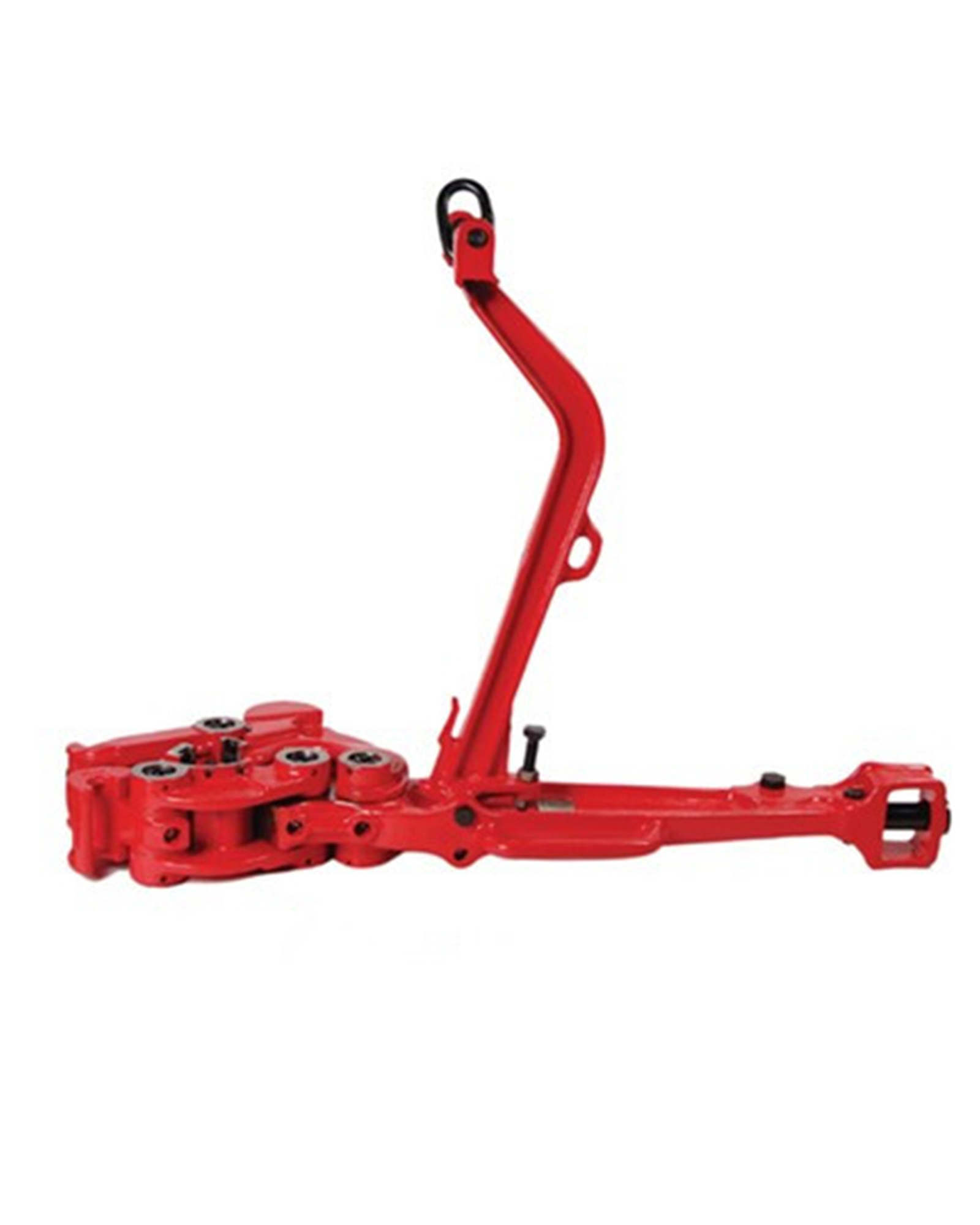
power tong snub line factory

Wire rope, one end of which is fastened to the end of a pipe tong handle attachment point and the other end secured to hold the tong stationary while the tong is in use.

A two-speed Hydra-Shift® motor coupled with a two-speed gear train provides (4) torque levels and (4) RPM speeds. Easily shift the hydraulic motor in low speed to high speed without stopping the tong or tublar rotation, saving rig time.
A patented door locking system (US Patent 6,279,426) for Eckel tongs that allows for latchless locking of the tong door. The tong door swings easily open and closed and locks when torque
is applied to the tong. When safety is important this locking mechanism combined with our safety door interlock provides unparalleled safety while speeding up the turn around time between connections. The Radial Door Lock is patented protected in the following countries: Canada, Germany, Norway, United Kingdom, and the United States.
The field proven Tri-Grip® Backup features a three head design that encompasses the tubular that applies an evenly distributed gripping force. The Tri-Grip®Backup provides exceptional gripping capabilities with either Eckel True Grit® dies or Pyramid Fine Tooth dies. The hydraulic backup is suspended at an adjustable level below the power tong by means of three hanger legs and allowing the backup to remain stationary while the power tong moves vertically to compensate for thread travel of the connection.
Originally, the drill string was assembled and disassembled using two sets of manually operated pipe tongs, wherein one set was applied to the "box" portion of the pipe at the upper end of the drill string in the borehole, and the other set was applied to the lower end (immediately above the threads) of the pipe being added or removed from the drill string.
The upper set of tongs was conventionally interconnected by a cable and torque gauge to a powered winch, and the lower set of tongs was connected oppositely thereof through a cable to a point of anchorage on the drilling rig. When the winch was activated, the connecting cable would turn the so-called "pipe tongs" to rotate the upper joint until the torque gauge registered the torque considered to effect a fluid-tight seal, (during make-up of the drill string), or to break the threaded connection in the case of disassembly of the drill string. The snubbing cable attached to the lower tongs would, of course, secure the lower tongs and thus the box portion of the lower joint of drill pipe from rotation during this process.
It will readily be apparent that such a process was time consuming and therefore expensive. More particularly, however, it was often extremely dangerous because of the possibility of cable breakage, and this possibility was increased when the so-called "manual" tongs used to rotate the upper pipe joint were replaced by hydraulically-actuated rotating tongs of the type depicted in U.S. Pat. No. 4,084,453, in order to achieve even higher torques prescribed for threaded connections in deeper boreholes.
Another disadvantage to such techniques, even after hydraulically-actuated rotary tongs came into widespread use, arose out of the inaccuracy of the measurement being provided by the torque gauge now interconnected with the snubbing cable. More particularly, it was long recognized that the torque gauge would accurately indicate the torque on the pipe only when the two cables were positioned to define force vectors which, in turn, were positioned at exactly 90 degrees of each other, and that this condition would only exist momentarily as the upper pipe was revolved. Thus, the problem of achieving a fluid-tight seal between adjacent lengths of drill pipe continued to exist even after the adoption of powered rotary tongs.
In some instances it has been found useful to couple the so-called "manual" back-up tong to the powered rotary tong assembly, whereby the two sets of tongs might be handled and operated as a unit, and whereby the drill string could be more quickly and conveniently connected and disconnected. In such an arrangement, of course, the two tongs tend to be snubbed together whereby at least one of the two cables were eliminated. Even this has become impractical with the need to develop increasingly higher torques by the rotary tong assembly, however, which were beyond the gripping capability of conventionally designed "manually-operated" tongs. Accordingly, there has long existed a need for powered back-up tongs which can develop a gripping force on the box portion of the drill pipe which is capable of immobilizing the drill string against the torques now required to obtain a fluid-tight pipe connection.
There have, of course, been many attempts to develop powered back-up tong assemblies having this capability, although all such attempts have been less than completely successful. One significant problem, which has prevented the use of designs similar to those incorporated in the rotary powered tong assemblies, has been the need to locate the back-up tongs at the box of the lower drill pipe and therefore immediately below and in close proximity to the lower surface of the rotary powered tongs. Another problem arises from the fact that, although a combination of the rotary and back-up tongs may eliminate the snubbing cables, the combined tong assembly is itself a hazard in the event of unscheduled vertical movement of any portion of the drill string.
These and other disadvantages of the prior art are overcome with the present invention, and improved powered back-up tongs are herewith provided for interconnection and use with powered rotary tongs.
In a preferred embodiment of the present invention, a powered back-up tong assembly is provided having a pair of oppositely movable jaw members which are arranged to be radially driven into gripping engagement with the box portion of a joint of drill pipe. More particularly, the two jaw members are supported by a pair of upper and lower plate members shaped substantially in conformance with the general configuration of the rotary tong assembly, and having an open throat portion for receiving and fitting the two jaw members about the pipe member sought to be secured against rotation.
Each jaw member is interconnected with its own separate driving assembly which, in a particularly suitable form, includes a hydraulic cylinder pivotally anchored at its rearward end between the two plate members, and having its piston rod hingedly connected to one end of a pivotally anchored lever having its other arm urged against the jaw member. Since both cylinders are sought to be cooperatively actuated, whereby both jaw members are driven in synchronism, hydraulic power is supplied to the cylinders through a flow divider so that both piston rods are extended in unison and through the same distance. Thus, both jaw members are extended exactly the same distance so as to avoid warping or misalignment of the drill pipe at the same time the rotary tong assembly (which is linked to the back-up tongs) is applying torque to the pipe assembly.
It will be apparent that, although the back-up and rotary tong assemblies are intended to be interlinked as a unit, the connection between the two must be flexible within prescribed limits. Furthermore, such flexibility must not only permit limited movement in the direction of application of the torque to the pipe member, but also limited movement between the two tong assemblies along the longitudinal axis of the drill string.
Referring more particularly to the matter of linkage of the two tong assemblies, the rotary tong assembly is preferably provided with three downwardly extending rod members which, in turn, are each preferably provided with a plurality of pin apertures at various locations along their length. The back-up tong assembly, in turn, is conveniently provided with corresponding apertures through which these rods will extend when the back-up tong assembly is positioned immediately below the rotary tong assembly. A shear pin is inserted through the aperture in each rod, which thereby selects the maximum vertical spacing sought to be maintained, and the back-up tong assembly then rests on these three shear pins. In addition, a spring or other resilient means is preferably disposed between the shear pin and the under surface of the top plate of the back-up assembly, to absorb impact when the back-up tong assembly is drawn against the rotary tong assembly as the two sections of drill pipe are screwed together. Similarly, the springs tend to soften the reaction when the two tong units separate, as by removal of a section of drill pipe from the drill string.
With respect to lateral movement between the two units, the holes to be provided in the back-up tong assembly are preferably formed in the manner of arcuate slots having a radius of curvature and position corresponding to rotation about the pipe string. More particularly, each unit is also provided with a rearwardly extending bracket member which tend to be urged toward each other when the rotary tong assembly applies torque to the pipe member, and thus a suitable torque sensor may be arranged to be compressed between these two brackets to provide an extremely accurate measurement of the torque applied to the pipe member unless the rods move against the ends of the slots.
It sometimes happens that the operator of the winch (not depicted), which supports the upper joint of drill pipe 4, will activate and lift that joint of drill pipe after it has been unscrewed from the box gripped by the back-up tongs, but before it has been released by the rotary tong assembly. Similarly, it will sometimes happen that the slips in the rotary table will fail to hold the drill string, and if the tong assemblies are gripped to the drill string, or even if only the back-up tongs are then gripped to the drill string, this may cause both tong units to be carried away from their suspension means. In both cases, this creates an extreme risk to personnel in the vicinity, by virtue of the collapse of several thousand pounds of equipment onto the drilling platform, and is another reason why powered back-up tongs have not previously been considered desirable.
In the present invention, this disadvantage is substantially overcome by the fact that, in either of these cases, the shear pins will sever to separate the back-up tong assembly from the rotary tong assembly. If the operator has inadvertently prematurely activated his winch, as in the first example, this will merely lift the rotary tong assembly free of the back-up tongs without other misadventure. If the drill string begins to collapse into the borehole, as in the other example, this may carry the back-up tong assembly to the floor of the drilling ring, but the rotary tong assembly will be freed to remain in its normal position.
Accordingly, it is an object of the present invention to provide improved back-up tongs and method for securing a pipe member against rotation by powered rotary tongs and the like.
It is further an object of the present invention to provide improved hydraulically-actuated back-up tongs for securing drill pipe and the like against a high rotational torque.
It is further an object of the present invention to provide improved back-up tong means and method for cooperating with powered rotary tongs to develop a more accurate measurement of torque being applied to a pipe member and the like.
It is also an object of the present invention to provide improved back-up tong means releasably interconnectable with powered rotary tongs and the like.
Referring now to FIG. 1, there may be seen a simplified pictorial side view of apparatus embodying at least one concept of the present invention, and including a suitable rotating power tong assembly 2 disposed about an appropriate location along the length of a joint of drill pipe 4. In addition, and located immediately below, there is provided a back-up power tong assembly 3 of the type hereinafter described in detail. The rotating power tong assembly, which operates to apply rotational torque to the length of drill pipe 4, is preferably provided with a plurality of support rods 5 which, in turn, extend fixedly down in parallel with the drill pipe. The back-up power tong assembly 3, therefore, will preferably be provided with suitable apertures whereby it may be disposed about these support rods 5, to provide for a minimum gap 14 or spacing between the rotating power tongs 2 and the back-up power tong assembly 3.
At the lower end of each of the support rods 5, there is preferably provided a plurality of suitably spaced-apart apertures through which a shear pin 6 may be inserted. Between the shear pin 6, and the back-up power tong assembly 3, there is preferably provided a suitable washer 9 or other appropriate retaining means, and a suitable spring means 7, whereby the back-up power tong assembly 3 is supported in close proximity to the underneath surface of the rotating power tong assembly 2.
Referring again to FIG. 1, it may be seen that the back-up power tong assembly 3 is preferably provided with a rearwardly extended bracket 11 which supports an appropriate torque sensor 10. In addition, the rotating power tong assembly 2 is also provided with an appropriate bracket 12 which extends down to drive laterally and rotatably against the torque sensor 10 whenever the rotating power tong assembly 2 is actuated to apply rotational force or torque to the joint of drill pipe 4. Since the back-up power tong assembly 3 is designed to immobilize the length of drill pipe 4, each of these brackets 10 and 12 tend to be driven together, to not only cooperatively snub both the rotating power tong assembly 2 and the back-up power tong assembly 3, whereby they do not revolve dangerously about, but whereby they cause the torque sensor 10 to provide an appropriate indication of the amount of torque being applied therebetween, (and also consequently to the length of drill pipe 4).
It should be noted that the function of the shear pin 6 is not only to provide for coupling of the back-up power tong assembly 3 to the rotating power tong assembly 2, but also to act as a safety release in the event these two components inadvertently separate. More particularly, it sometimes happens that the drill string (in this case represented by the portion of the drill pipe 4 which is gripped by the back-up power tong assembly 3) tends to drift downwardly into the bore hole due to failure of the slips in the rotary table (not depicted). Although the rotating power tong assembly 2 is appropriately supported by suspension from above (by means not depicted in FIG. 1), such suspension cannot carry the weight of the drill string, and thus there is an immediate danger that two power tong assemblies 2 and 3 may be brought down with attendant risk of injury to personnel in the immediate vicinity. However, the shear pins 6 are intended to sever in such an eventuality, thereby relieving the rotating power tong assembly 2 from the weight of the drill string represented by the length of drill pipe 4, whereby only the back-up power tong assembly 3 will descend to the floor of the drilling platform (not depicted). If the back-up power tong assembly is then actuated to engage the length of drill pipe 4, the rate of descent of the back-up power tong assembly 3 will be not more rapid than the rate of descent of the drill pipe 4 into the bore hole.
Similarly, it sometimes happens that the operator of the winch (not depicted) which supports the upper end of the drill pipe 4, will actuate and raise the pipe after it has been unscrewed from the lower portion of the pipe 4 which is gripped by the back-up power tong assembly 3, but before the rotating power tong assembly 2 has been disconnected from the upper end of the pipe 4. In this event, both of the power tong assemblies 2 and 3 would be carried dangerously upwardly except that the shear pin 6 will sever to disengage the back-up power tong assembly 3 from the rotating power tong assembly 2. Since the winch (not depicted) is easily capable of supporting the rotating power tong assembly 2, as well as the single joint of drill pipe 4 being gripped thereby, this greatly minimizes the risk of injury to the adjacent personnel.
Referring now to FIGS. 2-6, there may be seen simplified pictorial views of the back-up power tong assembly 3 generally depicted in FIG. 1, and further showing that this assembly includes a suitable top plate 20 with elongated arcuate slots 15 for containing the three support rods 5. In addition, there is a washer 8 or other suitable retaining means interposed between the upper end of each spring 7 and the lower surface of the top plate 20, for the purpose of engaging the upper plate 20.
It will be noted that the elongate arcuate configuration of the slots 15 provide for sufficient movement of the rods 5, whereby the brackets 11 and 12 may be brought together to cause the plunger 10A, of the torque sensor 10, to provide an accurate indication of the torque developed between the power tong assemblies 2 and 3 when the rotating power tong assembly 2 is actuated to rotate the pipe member 4, but not such that slots 15 will limit such travel prior to reaching the torque desired, and to then provide a false reading of the torque actually applied to the pipe member 4.
Referring again to FIGS. 2-6, it may be seen that the back-up power tong assembly 3 is provided with an open throat portion 21 whereby the rotating tong assembly 2 may be inserted about the pipe member 4. More particularly, the throat portion 21 is a space formed by the upper and lower plates 20 and 54, and more particularly by the spacing between the guide blocks 21A-B which, in turn, cooperate with a bracing block 42 to provide slidable support and guidance for a pair of jaw members 22 and 23 adapted to be driven into gripping engagement with the pipe member by levers 28 and 29. More particularly, the left jaw member 22 may be seen to be provided with a pin 26 and rotatable bushing 24 which, in turn, is urgeably engaged by the lever 28 which, in turn, is pivotally interconnected with the left hand end of the bracing block 42 by means of pivot pin 30. Rotation of the lever 28 about pivot pin 30 is affected by the driving assembly composed of the hydraulic cylinder 38 having its piston rod 36 and clevis member 34 interconnected with the opposite end of the lever 28 by hinge pin 32. In addition, cylinder 38 is hingedly fixed between the upper and lower plate members 20 and 54 by hinge pin 40, whereby extension of the piston rod 36 will rotate the lever 28 in a counterclockwise direction to drive the left hand jaw member 22 against the pipe member 4.
Operation of the back-up power tong assembly 3 may be achieved by an actuating valve 61, which is functionally suggested in FIG. 7, to connect hydraulic power through fluid supply line 60A and 48, to an appropriate flow equalizer device 47, and thence equally through check valves 45 and 46 to extend lines 43 and 44 leading to the extend ports of the hydraulic cylinders 38 and 39. Extension of piston rods 36 and 37 will, of course, be accompanied by return flow of the hydraulic fluid through return lines 49 and 50, and thence by way of the fluid supply line 51 to the hydraulic fluid supply 60 which is suggested functionally in FIG. 7.
It should be noted that the jaw members 22 and 23 are not only driven slidably between the bracing block 42 and the left and right-hand guide blocks 21A-B to securely engage the pipe member 4, but that such engagement is maintained by the check valves 45-46 unless and until the actuating valve 61 is intentionally repositioned. More particularly, it is the function of the check valves 45 and 46 to trap hydraulic fluid within the extend lines 43 and 44 whereby the piston rods 36 and 37 are maintained in their extended position regardless of whether hydraulic pressure is present in lines 43 and 44. Alternatively, however, when it is intended to retract the piston rods 36 and 37 to release the jaw members 22 and 23 from the pipe member 4, it will be seen in FIG. 7 that the actuating valve 61 may be positioned so as to apply hydraulic power through intake line 51, and to reconnect line 48 to the return line 60B leading to the hydraulic power source 60 as indicated in FIG. 7. Accordingly, the arrival of hydraulic power through line 51 will not only connect hydraulic fluid through lines 49 and 50 to the return ports of cylinders 38 and 39, such power will also be applied through lines 52 and 53 to release the check valve 45 and 46, whereby hydraulic fluid may now return through lines 43 and 44 to line 48, and may thereafter flow through the actuating valve 61 to the return line 60B of the hydraulic power supply 60.
As hereinbefore stated, it is essential that maximum travel of the jaw members 22 and 23 be provided for, due to the fact that the pipe member 4 (and especially that type of pipe employed to compose a drill string), be securely engaged against rotation by the rotating power tong assembly 2. It will thus be noted that the travel limits of jaw members 22 and 23 will not only be determined by the configuration of the bracing block 42 and the left and right-hand guide blocks 21A-B, but also by the position of the pivot pins 30 and 31 between the opposite ends of the two levers 28 and 29. In other words, the greater the spacing between pins 30 and 32 in the lever 28, and also between pins 31 and 33 in lever 29, the lesser the travel of the two jaw members 22 and 23 upon extension of the piston rods 36 and 37. More particularly, however, the greater the spacings between pins 30 and 32, and between pins 31 and 33, the greater the driving force which may be applied to jaw members 22 and 23 by levers 28 and 29, to thereby reduce the size of the hydraulic cylinders 38 and 39 needed to affect back-up engagement of pipe member 4.
As hereinbefore stated, it is a primary function of the bracing block 42 to provide for slidable support for the jaw members 22 and 23. In addition, however, the bracing block 42 also interconnects the two forkedly extending portions of the top and bottom plate members 20 and 54 which define the throat portion 21 of the back-up power tong assembly 3, whereby these portions are prevented from spreading when the jaw members 22 and 23 are subjected to an opposing force from the rotating power tong assembly 2, and whereby the jaw members 22 and 23 may become disengaged from the pipe member 4. It should be noted, however, that maximum spacing between pins 30 and 32, and between pins 31 and 33, may require that the bracing block member 42 be provided with concave aperture 21C to accommodate the pipe member 4.
Referring now to FIG. 5, it will be noted that the bottom plate 54 does not extend about the two rods 5 on the opposite sides of the open throat portion 21, and that the arcuate aperture 55, which surrounds the rearward rod 5, is substantially larger than its corresponding aperture 15 in the upper plate. The reason for this is that it is the upper plate 20 which carries the entire weight of the back-up tong assembly 3, therefore there is no need to extend the lower plate 54 about any portion of the front pair of rods 5. Further, since the back-up tong assembly 3 is intended to be released entirely from the rods 5 upon severing of the shear pins 6, it is essential that the arcuate aperture 55 in the lower plate 54 be larger than the washer 8, whereby the back-up tong assembly 3 may drop free of all portions of the rotary tong assembly 2.
Referring again to FIG. 2, it will be noted that, in this type of back-up tong assembly, no rotational force or torque is inherently developed merely by engagement of the pipe member 4 by the jaw members 22 and 23, inasmuch as the gripping force is generated, in the first instance, by extension of piston rods 36 and 37. In the case of the rotary tong assembly 2, however, this unit will develop a tendency to revolve oppositely the direction of torque which is applied to the pipe member 4, and in the case where a section of pipe is sought to be added to the drill string, this torque will tend to develop in a counterclockwise direction. Accordingly, in such an operation the rearward bracket 11 tends to snub the revolving rotary tong assembly 2, and further to support the sensor 10 against compression of the sensor piston 10A by the bracket 12 of the rotary tong assembly 2.
This will, of course, be reversed during break out length of drill pipe from the drill string, since the rotary tong assembly 2 will tend to revolve in an opposite direction when unscrewing drill pipe. Thus the two bracket members 11 and 12 will tend to separate, rather than to draw together, and thus no torque measurement will be provided by the sensor 10. This is inconsequential, however, since a torque measurement is only required to indicate when sufficient torque has been generated during interconnection of the length of drill pipe in the drill string, and since torque is only required in a magnitude sufficient to break apart a threaded joint when the drill string is being disconnected. It will also be noted that, during disassembly of the drill string, the two bracket members 11 and 12 will no longer snub each other together. However, this function will be performed by the rods 5 moving within the arcuate slots 15 in the top plate 20.
As hereinbefore stated, a back-up tong assembly of the type hereinbefore discussed is particularly suitable for use with drill pipe which, although relatively small in outside diameter, requires applications of very high torque both to interconnect and disconnect the threaded connections, by reason of the particular arrangement of levers and hydraulically actuated piston rods. However, a back-up tong assembly of this type is clearly not limited to use with only drill pipe, but is particularly useful with any type of threaded members sought to be connected or disconnected, and especially with respect to well tubing joints and lengths of sucker rod and the like. In addition, embodiments of the invention may be often useful for many larger sizes of tubing or pipe, such as threaded well casing, line pipe, and the like.

The present invention relates to oil field devices. More particularly, the present invention relates to an apparatus which has the ability to position and properly align a power tong around sections of oil field pipe on the rig floor by a single deck hand.
In the drilling and completion phases in exploring for oil and gas, pipe tongs have been utilized for engaging lengths of casing, drill or completion pipe, known generally as tubular members, end to end, by rig floor personnel operating power tongs directly and in close proximity to the tubulars on the rig floor. A typical power tong comprises a first set of jaws which hold one section of pipe stationary while a second set of jaws rotate the next section to make up or break up the joint. The power tongs may weigh a few thousand pounds and are usually supported from the rig by a cable that allows the power tong to be moved manually by the rig floor personnel to engage the pipe, or disengage from the pipe, and be positioned away from the pipe string, to allow other work to proceed. Interconnected by a hydraulic cylinder, often referred to as a ‘lift’ cylinder, the power tong is connected on the one end to the rig cable and to the other end there attached to the power tong. The hydraulic cylinder allows the Power Tong Operator, from the operator"s position at the Power Tong, to make Vertical corrections, both upwardly and downwardly to the Power Tong for positioning on the make or break out of the pipe. Such a lift system is illustrated in FIG. 19, labeled “Prior Art” is well known in the art.
However, because of the size of the power tongs, more than a single individual, often times two or three men, are required to move the tong into position, and operate the tong to make up or break the joint, and then to manually swing the tong, hanging from the cable, out of the way, and engage it in a position away from the pipe, so that the rig personnel can proceed to other chores. This manual operation of the tong in and out of position must be done with care, since the tong, swinging free from the cable, may strike one of the workers, or inadvertently disengage from its position and injure workers or damage materials on the rig floor.
Typically there are two types or composition of pipe or tubulars screwed together one piece to another, end to end, until the entire number of sections of pipe required for the job are joined together and run into the ground below the rig floor. One composition of pipe is steel pipe which maybe screwed together without much care taken by the deck hand and/or the type of handling tool and power tongs to be used. However, another composition of pipe utilized for this type work is Chrome 13 or similar soft composition which requires much care when screwing one pipe section to another section requiring the Power Tong to be carefully placed on each section to prevent damage to the external coating of each pipe section. As the Power Tong comes in contact with each Chrome pipe section, care must be taken not to have damaging contact which may result in rapid deterioration once exposed to a harsh environment down hole. The difficulty in operating power tongs in this fashion has led to attempts to provide a different system to utilize and maneuver power tongs on the rig floor.
For example, U.S. Pat. No. 6,318,214 entitled “Tong Positioning Apparatus,” discloses a power tong support apparatus having a frame, and a base movably positioned on the frame, with the power tong support attached to the base and movable to and away from the power tong. However, one of the drawbacks to this device is that the device requires a rather large and cumbersome frame to support the tong support member, which is not desirable because of the scarcity of rig space. Further, the device does not appear to allow the tong support member to operate at variable heights from the rig floor, which is necessary, since the pipe sections may be connected and disconnected at various heights above the rig floor.
In one embodiment what is provided is an improved tong positioning and alignment apparatus which includes abase with a drip pan, designed to capture accidental oil spill or drip from the system, positionable on the rig floor; a hydraulic cylinder positioned on the base, having a first end engageable to a rear support member and a second end engageable to a pivotal moment arm; a forward shock attachment arm(s) engaged at a first end to one of three attachment points on the moment arm, and a second end which attaches to a tong frame attachment point(s) on the tong. The (single) moment arm may be bilaterally functional provided the system has a pivotal shaft extending outwardly on each side of the forward support member whereby the forward end of the moment arm actually has two forward ends, one each on each side of the forward support member and each having multiple bores thus emanating the structure for an additional forward shock absorber attached thereof.
Further, the tong frame is designed with a forward tong frame pivotal attachment member to accommodate a forward shock absorber on each side which additionally provides greater strength and stability during the torque process and further limits the bending and shearing effect of the tong while in tension with the tubular section. The greater the stress established through the bending and shearing effect applied to the threaded connection, the greater the probability the torque turn graph may display a bad connection thus the potential to discard that particular threaded section. Each forward shock attachment arm includes a pair of shock absorbers engaged along its length to provide a smooth, non-jerking motion both vertically and horizontally in moving the power tong. Each forward shock attachment arm may also be designed with more than two shock absorbers or the use of only one single shock absorber is desirable if the handling procedure with the size and weight of each power tong thus dictates the need for such. The tong positioning apparatus is designed to be remotely operated by hydraulic, air, air over hydraulics, electronically, hard wired or wireless or otherwise by a single operator. There is further provided a plurality of attachment points on the rear support member, and a plurality of pivot points for the moment arm, to allow for various vertical and horizontal positioning of the tong during makeup and breakup of pipe on the rig floor. Further, the apparatus includes a safety shield system to insure the workers are protected from inadvertent contact with moving parts of the apparatus.
Further there is provided a means for aligning the pipe within the tong apparatus by so that pipe, such as Chrome 13, or similar soft pipe, can be carefully guided into the tong, and eased in position, without the pipe wall making forceful contact with the tong. There is further provided at least two cameras which view the entire operation so that the manipulation of the pipe can be accomplished by an operator from a remote location.
In one embodiment is provided an improved tong positioning and further to provide an alignment apparatus which insures a safe working environment and saves time, promotes efficiency and reduces fatigue while operating power tongs on a rig.
In one embodiment is provided a tong positioning and alignment apparatus which requires a minimum of rig space, is able to be operated by a single deck hand through a power system operated at the location of the power tong operations or remotely operated from any location on the rig floor.
In one embodiment is provided a tong positioning and alignment apparatus wherein a hydraulic cylinder or air cylinder, hydraulic motor, chain or belt drive, cam over action or otherwise any driver when activated, operates a moment arm, pivotally attached to a forward support member, which is attached through a shock absorbing member downward or otherwise vertically, upwardly or downwardly, or horizontally to a forward pivotal support member on the power tong frame to allow forward and rearward movement of the power tong at various heights above the rig floor.
In one embodiment is provided a tong positioning and alignment apparatus engineered to provide strength and stability to contain the predetermined rotational force of the tong and prevent potentially serious injury to any deck crew member should the snub line fail or be improperly adjusted. It is well known in the art that great torque is applied to the pipe by the upper tong jaws as the lower tong jaws hold the pipe in place. With such great torque applied to the pipe section presents the possibility of malfunction of the lower tong jaw which restrains the pipe while the upper tong jaw is making up the threaded connection to the desired torque value. Should the lower jaw fail and the upper tong continues its predetermined rotational path, the present invention is designed to contain and prevent said rotational path of the upper tong and further prevent possible serious injury or death to the rig crew members.
In one embodiment is provided a tong positioning and alignment system which includes a protective frame and cover which can be retracted in and out of position when necessary.
In one embodiment is provided a tong positioning device which incorporates a shock absorber system to allow the jaws of the device to contact soft pipe, such as chrome pipe, without damaging the wall of the pipe.
In one embodiment is provided a tong positioning and alignment device which incorporates a tubular guide plate on the tong but preferably attached on the hydraulic back-up, or lower tong, to allow the soft pipe, such as chrome pipe, to be gently guided into the open throat of the tong and further to the tong jaws without damaging the wall of the pipe.
In one embodiment is provided a tong positioning and alignment device equipped with opposing intrinsically safe explosion proof video cameras in close proximity to the tubular guide plate and attached thereon. The video cameras are positioned to view each tubular section and further having a monitor mounted on the power tong visible to the tong operator and further a monitor located in the office of the rig supervisor to be utilized by the power tong operator and/or the rig supervisor as an aid to VHS or digitally record for later retrieval of said video for viewing and evaluation of (and store) the effect of the power tong positioner and alignment apparatus relative to the tubular guide plate in respect to the proper alignment of the upper jaw—die to each tubular section. In the event a problem is detected later in the completion phase, the VHS or digital recording is reviewed to determine if problems were associated with the tubular alignment and makeup procedure.
In one embodiment is provided a tong positioning device which requires minimum rig floor space, fewer personnel to work in a safer environment; makeup and break down pipe faster with less effort; and could be operated from a remote location on the rig floor.
In one embodiment is provided a power tong alignment system which is compact and easily attachable to the lower power tong and comprises the forward pipe section guide plate with pipe section/power tong alignment pads, two opposing intrinsically safe video cameras with view of the pipe section as the power tong is aligned and positioned on each pipe section, one on each side of the lower tong. Further, the power tong alignment system includes the tong door system which is operated by the power tong operator.
In one embodiment is provided a power tong well bore radial positioning and attachment device set out on a horizontal plane. In the running of casing, the power tong may utilize only the upper jaw set to rotate the upper tubular member while the lower tubular member is held in place by conventional manual tong(s) immobilized in place by a very strong cable referred to in the industry as simply a ‘snub line’ and further a snub line of approximate identical proportions is attached at the one end of the snub line to the line pull attachment located to the portion of the power tong away from the well bore and further the second end of the snub line cable is attached permanently to a rig vertical leg support or otherwise attached to a permanent substructure snub line attachment point as part of the rig floor and further the lower tubular member may be held in place by a mechanical slip bowl mechanism inset at the well bore and the sheer weight of the combined tubular string prevents inadvertent rotational movement of the lower tubular body.
In one embodiment the power tong, as it relates to the snub line, is directed or positioned in the makeup or backout mode and the power tong, under extreme torque application and further as the tong begins the anticipated rotational process in relation to said tubular, that portion of the power tong using the measurement farthest from the well bore center commonly known in the industry as the (handle arm length or handle length), the torque application hereof causes said power tong to swing forcible into a predetermined radial arc such as determined proportionally by the length from the well bore center to the snub line attachment point at the rear of the power tong (handle length), thus causing the snub line to become taunt while in effect the power tong while being supported by a cable shifts position somewhat on the radial axis in relation to the well bore and handle length. The horizontal position shift of the power tong is in direct relationship with the power tong as torque is applied to the tubular member in either the make up or back out mode.
In one embodiment this radial arc as herein implied and suggested refers to the logically necessary sequence of events in relation to the distance from the center of the well bore to the point of attachment to the power tong (handle length) with the snub line therefore the requirement for the utilization of the current invention when said power tong is ‘pushed or positioned’ by a positioner and control device or otherwise a robotic arm.
In one embodiment is provided a mechanism to prevent damage to the connection arm of said positioner and/or to cause the power tong to shift along the ‘radial arc’ gently controlled by coil spring(s) (with 10.198 lb/in or 1.1522 newton/meter), shock absorber(s) or otherwise that may be required as established through the logically necessary sequence of events.
In one embodiment is provided an apparatus where as torque is applied by the power tong causing the handle length end of the power tong to advance in the direction determined by the make up or break out procedure.
In one embodiment as further defined by the ‘handle length’ to advance in either direction depending on the make up or break out of the tubular member. In one embodiment is provided an apparatus which allows for the said radial movement relating to the axial well bore assignment of the power tong and as the torque increases causing handle length rotational movement to said power tong to gently rotate without damage to the power tong or positioner.
In one embodiment is provided an apparatus where the connection torque value between the lower tubular member and upper tubular member is made up as predetermined, the power tong, with the assistance of the integral memory mechanism, positions the power tong to the proper alignment and the power tong is released from the tubular member, assumes the original inline position and the power tong is extracted from the make up break out position to the secure position away from the well bore and tubular member at which time the tubular member is lowered down hole by the drilling rig crew.
In one embodiment is provided an integral memory mechanism composing a 1.5 inch (3.81 centimeter) solid steel radial bow designed to the parameters set out herein and designated through said distance achieved utilizing the parameters from the well bore center to the end of the power tong.
In one embodiment is provided a radial attachment apparatus that insures a safe working environment and saves time, promotes efficiency and reduces fatigue and further provides a smooth transition of the power tong from the torque position on the tubular member to the relative horizontal plane of the power tongs when removed from the tubular member on the rig floor.
In one embodiment is provided an improved Power Tong Well Bore Radial Apparatus which includes a base positionable on the Power Tong; an arm having a first end engageable to the Power tong rear support member and a second end engageable to the housing of the invention; a radial solid round bar positionable with ‘V’ groove steel bearings which are centered on the round bar; a solid square bar or rectangular bar with identical radial measurements as the above and further supported by roller bearings.
In one embodiment is provided a tong positioner having the ability to facilitate radial and/or horizontal positioning of a power tong around sections of oil field pipe or casing on the rig floor by a single operator at the equipment or remotely through hydraulics, wireless or otherwise.
One problem with operating the power tongs when connected to only an upper tubular (and the lower tubular being rotational fixed by some device independent of the power tongs) is that relatively large dynamic rotational reaction forces (reacting to the rotational torque being applied to the upper tubular member) will be transferred back to the power tongs and then back to through to the tong positioner. These dynamic rotational forces can in some instances damage, bend, or cause portions of the tong positioner (such as the connecting arm) to fail prematurely. In one embodiment the size of these relatively large dynamic rotational reaction forces (which are ultimately transmitted to the tong positioner) can be reduced and/or minimized by allowing a relative rotational movement (in a substantially horizontal plane) between the powered tongs and the tong positioner. In one embodiment this allowed relative horizontal rotation between the powered tongs and the tong positioner is called a floating connection between these two devices.
In one embodiment this relative rotational movement can occur along a predetermined rotational radial arc of the powered tongs relative to the tong positioner. The radius of curvature of this predetermined arc is expected to be the distance between the center of the upper tubular member and the connection point between the powered tongs to the tong positioner. In one embodiment the amount of the size of the radial arc can be adjustable for accommodating different sized powered tongs with different distances between the connection point between the tong positioner and the point of rotation for the powered tongs (e.g., the center of the upper tubular member). In one embodiment adjustment of the radial arc can be obtained by the switching out of radial arc members from a set of different predetermined radial arc members. In one embodiment adjustability can be obtained by having the radial arc member comprised of a plurality of pieces and the pieces being pivotal to different radius of curvature. In one embodiment the radial arc member can be bendable.
In one embodiment a pair of springs can be used so that relative rotational movement will cause one spring to expand and the other spring to compress. In this situation the two springs can be said to have a memory where, after the dynamic rotational reaction forces subside, the two springs will tend to move the powered tongs back to the relative rotational position seen before the dynamic rotational reaction forces were first applied. In one embodiment the biasing member(s) are called an integral memory mechanism which automatically positions the power tongs in a proper alignment situation, after the upper tubular member is released by the power tongs, and before the next application of the powered tongs to an upper tubular member. This would be after the dynamic reaction torque on the powered tongs subsides.
In one embodiment the integral memory mechanism can include a 1.5 inch (3.81 centimeters) steel radial bow (such as being designed to the parameters set out herein and designated through distance achieved utilizing the parameters from the well bore center to the end of the power tongs). In one embodiment along the handle arm length can be provided a series of tension/compression springs (preferably with spring constants of about 10.2 lb/in or 1.15 newton/meter) coupled with ‘v’ groove steel roller bearings. In one embodiment a 2 inch (5.08 centimeter) solid steel radial bow stock with steel guide roller bearings can be used for ease of movement throughout the predetermined radial arc.
In one embodiment the amount of force resisted by the radial springs when compared to the torque applied by the power tongs is negligible. In this embodiment the powered tongs can substantially freely float (rotationally in a horizontal plane) relative to the positioner so that horizontal rotational torque loading transmitted from the power tongs to the positioner is minimized—thereby minimizing any damage to the positioner arm from bending loads. In this embodiment a snub line ultimately stops the powered tongs from rotating in a horizontal plane. The snub line can also include a load cell measuring the force applied by the power tongs on the snub line which force can be converted to the torque on/from the tubular when the moment arm “handle” is taken into account. The moment arm “handle” can be the radial distance from the center of the tubular to the connection point of the snub line.
In one embodiment the radial spring is strong enough to overcome friction and reposition the powered tongs relative to the tong positioner (after the dynamic or shock torque loading subsides from the powered tong tightening or loosening the tubular) to its original radial starting position relative to the positioner. The strength of the radial spring would have to overcome the frictional forces from the rollers and the bow.
In one embodiment, to provide a “true” torque reading from the load cell on the snub line, the relatively small amount of forces applied by the radial spring should be specified and given to the rig so that the rig can take this force into account when calculating the “true” torque applied by the power tong on the tubular (instead of merely the force read by the loading cell on the snub line). As the resistance of the radial spring will reduce somewhat the force read by the load cell (although this may be negligible) because the radial spring does somewhat resist rotation of the power tong.
In one embodiment this relative rotational movement can be dampened through mechanical means such as frictional resistance along with in addition of one or more biasing means (helical springs and/or other type springs). In one embodiment the risk of damage to the connection arm of a tong positioner is reduced and/or eliminated by allowing the power tongs to shift and/or turn along a “radial arc” while such shifting/turning is gently resisted by one or more dynamic and/or shock loading absorption devices (such as one or more springs (e.g., having spring constants of about 10.2 lb/in or 1.15 newton/meter) which can also include dampening devices (such as shock absorber(s))).
In one embodiment specific dampeners (e.g., shock absorbers) can be used to further dampen and/or reduce the amount of the dynamic rotational reaction forces ultimately transmitted to the tong positioner. In one embodiment the amount of resistance to relative rotational movement between the tong positioner and the powered tongs can be adjusted (such as by allowing the switching out of springs with different spring constants or a screw type adjustment which tightens the springs).
In one embodiment an on/off switch for allowing/disallowing relative rotational movement between the powered tongs and the tong positioner can be provided which can stop and/or restrict the allowed relative radial movement between the powered tongs and the tong positioner
FIGS. 2A and 2B illustrate side views of the preferred embodiment of the tong positioning system of the present invention moving power tongs into and out of position relative to tubular members;
FIG. 3 illustrates a side view of the preferred embodiment of the tong positioning system of the present invention as it would be utilized in the plurality of positions on the rear support member, forward support member, and moment arm;
FIG. 32 is a sectional view of the second embodiment of the apparatus of the present invention, taken along lines 29-29 of FIG. 28 and illustrating an alternate rotating device in the form of a worm gear arrangement;
FIGS. 1 through 18 and 20 through 26 illustrate the preferred embodiment of the present invention; i.e., the improved tong positioning device (the “device”) by the numeral 10. FIG. 19 illustrates a prior art lift system for a power tong, so that the operation of the present invention may be more fully explained.
The rectangular container 18 would contain a power drive system 20, which as illustrated, comprises a hydraulic cylinder 22, having a piston member 24 movable within the cylinder 22, driven by hydraulic fluid pumped through lines 26, 28, as is commonly known in the art. Although a hydraulic cylinder, containing hydraulic fluid is illustrated and discussed, it should be made clear that the scope of the power system may include diesel hydraulics, forced air pressure, electronic signaling between a sender and a receiver, or other similar systems, such as a belt or chain drive or cam over system. As illustrated, the first end 30 of the hydraulic cylinder 22 is secured to a vertical rear support member 32 which would be secured onto base plate 14 through welding or the like, as seen in isolated view in FIG. 4. The end 30 of the cylinder 22 is engaged into a first lower port 34, and held in place with a pin 36 and a cotter pin 38. There are two other ports 34 along the length of the rear support member 32, the purpose to be explained further. Likewise, returning to FIGS. 1 through 3, the piston 24 as engaged at its end to the lower end of a moment arm 40, in the same manner that the first end 30 of the cylinder 22 is engaged to the rear support member 32, i.e., a pin 36 and cotter pin 38.
Returning to FIGS. 1 through 3, and making reference particularly to FIGS. 8 through 12, there is illustrated the forward shock attachment arm 50, which is engaged at a first end 52 to one of the bores 48 in the moment arm (in FIG. 1, connected at the mid bore 48), through the use of a u-shaped connector member 53, having a first connection point to the moment arm 40 via bolt 55, and a second open-ended connection point to the end 52 of attachment arm 50 via bolt 57. This allows pivotal movement between the moment arm 40 and the attachment arm 50. The attachment arm 50 comprises first and second portions 54, 56 which are engaged to one another by a pair of air or gas cylinders 60, positioned on either side of he portions 54, 56, as illustrated. There is further illustrated a pair of external members 70 for limiting the expansion and contraction of the attachment arm 50 during its operation while said external members are further utilized as stabilizing guides to reduce any shearing, bending and/or rotational movement of the forward shock limiter and combines to further support the designed alignment procedure of the Power Tong in relation to the Tubular Section. Also known in the art is the great amount of torque applied to the pipe by the upper tong jaws as the lower tong jaws holds the pipe 90 in place. These members 70 span across to each portion 54, 56, and would allow for limited expansion and contraction of the two portions 54, 56, into and away from one another as the case may be. There are provided ports 55 in the members 70, as seen in FIG. 8, to preset the desired limit of expansion and contraction. The movement of the two portions 54, 56 are controlled by the air cylinders 60, which afford a precise movement, and limits or eliminates a sudden, jerking movement of the apparatus as it would be utilized to move the tong into position around a section of tubular member or away from the tubular members after make up or break down. FIGS. 11 and 12 illustrate the limits in which the movement of the two members 54 and 56 relative to one another during use of the device, by the inward and outward movement of the two sections 73, 75 of the limit members 70.
The second end 59 of the attachment arm 50 is pivotally engaged at point 72 to the tong support member 74, via a single bolt 76, which also allows pivotal movement between the attachment arm 50 and the power tong 80. One example of such an attachment method would be seen in FIG. 19 in this application. It should be made clear that although the power tong 80 is secured to the device 10 at attachment point 72 between the attachment arm 50 and the tong 80, the device is being used primarily, if not exclusively to position the tong 80 onto and off of a section of pipe 90. In this embodiment, it is not supporting the very heavy weight of the power tong 80. The tong 80, as seen in FIGS. 2A and 2B, is being supported by (a hydraulic cylinder known as a lift cylinder, of the type of prior art lift cylinder, illustrated in FIG. 19, interconnected at each end to a cable 100, as is currently known in the art.
So, in general, as seen in FIGS. 2A and 2B, an operator would stand adjacent tong 80, and have access to the various operation handles 82, which are used to open and close the tong jaws and spin the pipe, all functions already known. However, with this device, the operator has access to a second set of handles 84 which operate the cylinder 22, to commence operation of the device. As seen in FIG. 2A, the tong 80 is engaged to the forward attachment arm 50 at point 72, as the tong 80 is suspended from a device as shown in prior art FIG. 19, by cable 100, near pipe 90. The upper end of the arm 50 is engaged to the upper end of the moment arm 40 at point 57, which allows pivotal movement between the two. The moment arm 50 is pivotally engaged along the middle opening 45 of the upper support member 47, with its lower end engaged to the piston 24 of the cylinder 22. In FIG. 2A, when the operator manipulates the hydraulic fluid to force the piston 24 rearward into cylinder 22 (arrow 102), the moment arm 40 is pivoted in the direction of arrow 105. When this occurs, the lower end 59 of the attachment arm 50 is forced in the direction of arrow 106, when begins to provide forward movement of the tong 80 in the direction of the pipe 90, arrow 108. Because of the construction of the attachment arm 50, including the cylinders 60, the movement of the tong 80 would be smooth, and when the tong jaws would make contact with the wall of the pipe 90, the contact would be cushioned and would not damage the pipe wall. This is particularly important when brass or other soft metal, such as chrome tubular members are being used in the operation. Of course, when the device 10 has engaged the tong 80 on the pipe, and the operation is complete, the operator would activate the hydraulic fluid to flow to the rear of the piston 24, through line 28. The piston 22 would be forced out from cylinder 22, arrow 109, and in doing so, would pivot the upper end 44 of the moment arm 40 in the direction of arrow 110, which would pull the lower end 59 of the attachment arm 50 in the direction of arrow 112, and in turn moving the tong 80 away from the pipe 90, in direction of arrow 114. This operation would allow smooth movement of the tong 80 to engage and disengage from the pipe 90.
One particular feature not yet discussed in the operation and construction of the device 10 is its ability to effect different vertical and horizontal movements between the moment arm 40, attachment arm 50 and the tong 80, based upon the relative position of the tong 80 on the rig floor, which may also function when utilized in conjunction with the hydraulic lift cylinder interconnected between the rig cable and the tong. This ability is illustrated in FIG. 3 and FIG. 19, Prior Art). As was discussed earlier, rear support member 32 included a plurality of bores 34 to which the rear end 30 of the cylinder 22 could engage. Likewise, the forward upright support member 47 included a plurality of bores 45 in which the moment arm 40 could pivot along its path. Further, the upper end 44 of the moment arm 40 included a plurality of bores 48 in which the end of the attachment arm 50 could engage. The function of these various attachment choices between the cylinder 22, moment arm 40 and attachment arm 50 is illustrated in FIG. 3. As seen, for example, when the cylinder is attached to the upper most bore 34 of the rear plate 32, the angle and distance of the movement of the piston 24 would be changed, which would effect the movement of the moment arm 40 relative to the movement of the attachment arm 50. Since there are three different attachment points on the rear plate 32, three different attachment points for the moment arm 40 on the forward plate 47, and three different attachment points between the end 44 of the moment arm 40 and the attachment arm 50, the various combination of the attachment points would modify the travel of the cylinder/moment arm/attachment arm combination relative to the movement of the tong 80. The overall effect would be the ability of the attachment arm 50 to engage the tong 80 at differing heights above the rig floor 17, without having to position the base 12 of the apparatus 10 at different heights on the rig floor. The combination of attachment points would compensate for these variations, which could be determined at each job.
FIGS. 14 and 15 illustrate views of scaffolding 160 which includes a scaffold board 162, usually a minimum of 12 inches in width, which is inserted into a first frame 164, having a single swivel leg 166, which allows the scaffold to be safely and temporarily secured out of the immediate work area of the well bore when not needed, secured to the base plate 14. The frame 164 would include a support frame 168, having an opening 170 for inserting the board 162 therethrough. The second end of the board would be inserted into a second frame 171, which would include a pair of legs 172, a support frame 170, and an opening 174 for inserting the board 162 therethrough. The second frame 171 would allow to tilt at an angle so as to engage the board 162 securely in place while the operators are standing thereupon to operate the upper tong in a casing running mode, the dual or multiple string completion operation. As illustrated, the frames 164 and 170 are height adjustable.
FIGS. 20 through 26 illustrate various views of the pipe guide and alignment system utilized as part of the present invention by the numeral 200. The system 200 would include lower power tong section 203, which is seen in FIG. 21, arrows 211 showing system 200 moving in the direction of pipe 207 for beginning the process. System 200 would include a pair of guide an alignment arms 204, 205, which would be movable as a length of pipe 207 makes contact with the forward plate portions 206, and the apparatus is guided toward pipe 207, into point 208, as seen in top view in FIG. 21. As the guide arms 204, 205 are contacted by pipe 207, the arms pivot away at pivot points 209, and as seen in FIG. 22, the length of pipe 207 begins to ease into the gap formed between the guide arms 204, 205 as the forward plates 206 begin moving in direction of arrows 210. While this is taking place, reference is made to the pair of cameras 212, which have begun to record the process which is taking place while the pipe 207 into the guide and alignment system. Turning now to FIG. 23, at this point, the pipe 207 has entered into the space 214 defined by the guide arms 204, 205, and the rear alignment pad 216, which extends from the alignment device 217. As the length of pipe 207 moves into space 214, the pipe 207 makes contact with the rear alignment pad 216, at which point the pad 216, affixed to arm 218 extending from device 217, moves rearward to absorb the contact of the pipe 207 against the pad 216, which results in no damage to the pipe wall. In FIG. 24, the pipe 207 is now within space 214, and the alignment arm 218 returns to its position to engage the pipe 207 between the pad 216 and the alignment arms 204, 205. It should be noted that each of the alignment arms 204, 205 each include a guide pad 220, which when the arms are re-engaged, as seen in FIG. 24, the guide pads 220 of the guide arms 204, 205 and the rear pad 216 have the pipe fully engaged for operation. In FIGS. 25 and 26, there is illustrated in full side view and in partial side view, respectively, the lower tong section 203, with a length of pipe 207 engaged therein, and the cameras 212 recording the action. As will be more fully explained below, the cameras 212 are intrinsically safe, explosion proof cameras, and are utilized so that a worker or operator may be undertaking the complete operation as described above from a remote location, while viewing the entire operation in detail, and would not be near the work site which would reduce the chance of accidents. Of course, at any time the operator, if viewing any improper operation, could shut down the tong operation from his remote location.
The utilization of three pivotal points is not limited in this configuration but may include fewer or more pivotal points in the application. The present invention has three basic components which include the base with the rear and forward support elements. The rear support would have a minimal of three pivotal points as was discussed, the lower most


 8613371530291