
power tong snub line supplier
Eckel offers a broad range of accessories to compliment our power tongs. From torque control systems and gauges to case handles and tong straps, Eckel has the right accessory option for your specific application.
Eckel offers torque control systems to monitor the torque turn values when making up tubular connections with the system automatically stopping tong operation once reaching a specific torque. Any flaws in the make-up process will be readily shown in a graph.
The Door Interlock is offered as an optional safety feature for use with the power tong to prevent accidental operation of the power tong when the door is open. The door interlock prevents tong operation whenever the tong door is open by impeding hydraulic fluid to the tong motor.
A hydraulic Tri-Grip® or Cam Backup tool is optionally supplied with Eckel tongs. In operation this tool provides a backup when in break-out or make-up situations. This hydraulically operated backup tool, uses hydraulic cylinders and a head arrangement to insure slip-free operation.
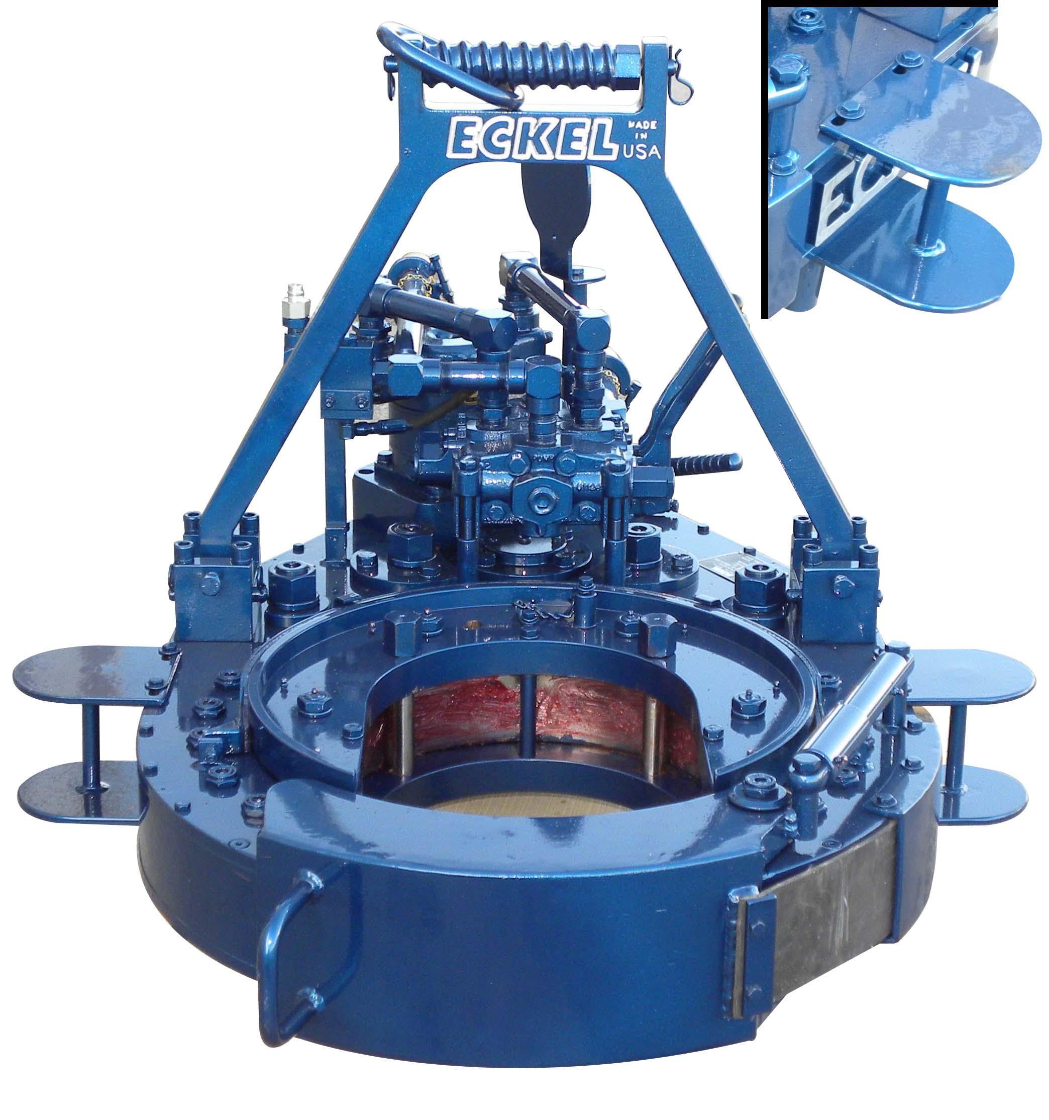
A standard feature on many of our tongs. Dies have evolved since tongs became commonplace in the oilfields. Eckel has been at the forefront of this developing technology with the development of larger wrap-around type dies for many of its tong models. We offer coarse tooth design for normal carbon steel pipe and collars and fine tooth for special alloys such as 9, 13, 23, 25 chrome and fiberglass to greatly minimize markings on the tubulars.
Designed for improved safety when handling the tong. Up to four Case Handles can be optionally mounted on most tong models. Large top and bottom caps help protect the operator when maneuvering the tong on and off the tubulars.
Eckel continues to set industry safety standards with the optional Finger Guard Option. This shield covers the gap between the tong door and tong body, without limiting door operation. Door will open and close freely.
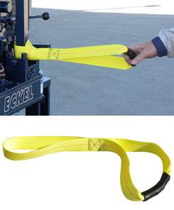
Industrial strength straps feature a rubber gripping surface to allow for easily pulling the tong on and off the tubular. These optional straps are mounted on the tong door and on both sides of the solid hanger area of the tong using a Lark"s Head Knot.
The adjustable motor port relief valve is used to control or limit the hydraulic pressure to the tong motor thus controlling the maximum torque output of the power tong. The valve controls only the hydraulic pressure to the tong motor leaving full system pressure available for other functions such as lift cylinder and hydraulic backup.
RPM Control: The RPM Control is a flow divider that decreases the amount of hydraulic fluid that reaches the tong, the remaining fluid is returned to the reservoir. By decreasing the amount of fluid reaching the tong the operator is able to control the maximum RPM"s the tong will deliver.
Tongs equipped with the optional Swivel Joints have improved hose life by absorbing system shock when pressured up and preventing twisting, kinking of the hydraulic hoses. In addition tongs are maneuvered more freely on the rig floor on and off the tubular.
The optional torque gauge assembly is used to measure the torque exerted in make-up or break-out operations. Consisting of a hydraulic cylinder and torque gauge connected together by a pressure hose, the torque gauge assembly senses and indicates the torque developed during an operation. For operation, the hydraulic cylinder is connected by a shackle to the rear of the tong; and a snub line is connected to the cylinder. The snub line is tied off to a solid part of the rig structure to form an angle of 90� in order for the gauge to indicate accurate torque readings.
This cylinder provides a means for raising and lowering the tong during operations and is recommended with tongs that have a hydraulic backup due to the extra weight of the tong. The lift cylinder maximum of travel varies depending on tong size.
The optional spring hanger is designed to permit the tong to move up or down to allow for thread length in make-up and break-out operations. When used, the spring hanger should be attached directly to the tong bridle ring and used as a hanger for the tong.

The tong should be secured for both make-up or break-out operation, by utilizing the snub line. If this is not done, the tong may be thrown against operator causing physical harm.
When using the mechanical shift lever to change speeds, the power tong must first come to a complete stop before shifting. When using tongs hydraulic shift two-speed motor to change speeds, the tong may be shifted "On the Run."
Eckel tongs have proven to basically to last forever with minimal maintenance as all they are manufactured with the highest quality of steel. Using Eckel equipment tells your customer that you have the highest quality equipment on the market.
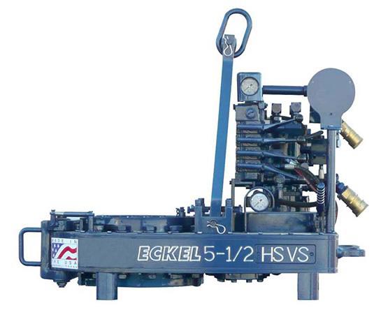
Tong size is determined by range of tubulars you will run. For example a 5-1/2 Hydra-Shift® is capable of running tubulars 5-1/2-inches and smaller while the 14 UHT is capable of running tubulars 14-inches and smaller. It is important not to use a large range of sizes with just one tong. If you have a 10-3/4 Standard and you regularly run 4-1/2-inch tubing with this tong, you might consider using a smaller tong.
PSI pressure determines the maximum torque the tong will safely be able to reach. Eckel rates all their tongs at the industry standard 2500 PSI. A competitor with a similar size tong may show more or the same torque as an Eckel tong due to a higher PSI from the power unit (which is in fine print) in an effort to fool you, thinking there tong is equal to the industry standard (Eckel tong.)
Gallons Per Minute determines the rotational speed of the tong. A low GPM will cause the tong to operate at a lower speed while a high GPM will result in the tong to rotate at a higher speed. Eckel offers an RPM (Revolutions per minute) Control which is a flow divider to decrease the amount of hydraulic fluid that reaches the tong if needed, the remaining fluid is returned to the power unit reservoir. By decreasing the amount of fluid reaching the tong the operator is able to control the maximum RPM of the tong.
Field tests have shown depending on several factors most power units used in above 32 degrees Fahrenheit conditions no matter if your hydraulic oil tank holds 200 gallons of oil, will exceed 150 degrees during a short 8 hour job. Most power units without hydraulic oil coolers exceed 170 degrees which is way past the recommended guide lines.
This website is using a security service to protect itself from online attacks. The action you just performed triggered the security solution. There are several actions that could trigger this block including submitting a certain word or phrase, a SQL command or malformed data.

Wire rope, one end of which is fastened to the end of a pipe tong handle attachment point and the other end secured to hold the tong stationary while the tong is in use.
Well pipe is made up by supporting a lower pipe section ("joint") in the well and then threading an upper joint onto it by means of a fluid-driven power tongs. The pipe assembly is lowered as new joints are added, down to depths of several miles. Threaded well joint connections, in order to seal properly and to have maximum tensile strength, must be accurately tightened ("made-up" in the trade) to a design torgue ("make-up torque") specified by the pipe manufacturer. The design torque must not be exceeded, since galling or breakage of the pipe threads may result. This is particularly true with pipe joint materials chosen for considerations other than strength, e.g. corrosion resistance and impermeability. Such materials are not only relatively soft--they can be quite expensive. In one recent case, 1000 joints (each thirty-three feet long) were removed from a well. Every joint had thread damage due to overtorquing and was considered scrap. This was pipe originally costing $2500 per joint. The importance of controlling the torque applied by the power tongs to the pipe can thus be appreciated, and in fact it is a requirement on many jobs that a running record of maximum torque at each joint be kept. (Various systems exist for making torque records during make-up, including applicant"s system described in co-pending applications Ser. Nos. 487,048 and 526,611.) Despite the existence of accurate torque recording systems, improper torquing continues to occur. The industry still seeks a system that will positively prevent thread damage from overtorquing.
The crossed thread problem is aggravated by violent or jerky movement of the tongs when power is first applied. The tongs frequently do not work smoothly--and are hard to control--at very low speeds. Also, the snub line, initially slack, tends to snap tight when power is first applied. These conditions make it difficult to control and/or record torque at the instant tongs operation begins, so that thread damage can occur even if a low-level torque limiter is used.
I have found that the above problems can be overcome by substantially increasing the overall gear reduction ratio within the tongs, for example, by a factor of five, so that the tongs jaw speed is correspondingly reduced, avoiding the problems of irregular start-up. This speed reduction is advantageously combined with a two-stage torque limiter system for (a) preventing the application of substantial torque during the initial phase of make-up and (b) limiting the maximum torque that the tongs can produce at the final make-up stage. Such a system is described in my co-pending application Ser. No. 629,421, supra.
Torque is automatically controlled during both tightening stages. In the final tightening stage, galling and breaking of threads is prevented by slowly turning the pipe and automatically disabling the pipe tongs when a predetermined torque level is reached.
A particularly important feature of the invention is that even after the tongs are disabled, a persistent torque is maintained by an adjustable choke in a shunt line between the high and low pressure sides of the power tongs.
The preferred embodiment of the invention is illustrated diagrammatically in FIG. 1. The major components are a conventional hydraulic power unit A, a power tongs T driven by fluid from the power unit, a tongs torque sensor/recorder B and a torque control module C.
The power unit A, as shown in FIG. 1, comprises an internal combustion engine 10, a hydraulic pump 12 driven thereby, a pressure regulator 14 downstream of the pump, and a fluid reservoir 16 upstream of the pump. In operation, the power unit delivers pressurized fluid through high pressure line 20, and receives fluid exhausted by the tongs via return line 22.
The tongs T have both conventional and novel aspects. A conventional body 30 supports rotary jaws 32 adapted to engage the outside diameter of a pipe P. The body houses a gear train details of which are not shown, including a two- or multi-speed transmission. Tongs of this type are well known. The transmission is manually shifted by means of a gear selector 34, with the ratio between high and low speeds being on the order of 4:1. The tongs are powered by a hydraulic motor 36 driving through two planetary gear reduction units 38 and 40 (FIG. 2) in series, each having about 51/2:1 reduction ratio. Further speed reduction is provided by spur gearing within the tongs body, so that the overall reduction is about 60:1 in high gear and 250:1 in low gear.
The tongs motor 36 is driven by fluid from the power unit, which enters the tongs via inlet line 42 and returns via exhaust line 44. A reversing shunt valve 46 on the tongs connected between the inlet and exhaust lines allows fluid to bypass the motor entirely when the valve is open. The shunt valve, normally open, may be moved to drive the tongs motor in either direction by a manual throttle handle 50 accessible to the operator.
Any torque applied to the pipe P by the tongs creates a reaction torque that tends to rotate the tongs around the pipe. This tendency is restrained by a snub line 54 connected between a stationary object and the tongs body along a tangent line as shown. The snub line 54 includes two load transducers in series for monitoring tongs torque. The first transducer 56 is an on-off pneumatic valve having adjustable spring bias. This valve opens when tension corresponding to a preset "hand-tight" torque in the range of 0-50 ft.-lbs. is applied. A manual override valve 58 in series with the first transducer 56 provides means by which the operator can disable the hand-tight torque control system, if desired.
An important feature of the invention is the on-off valve 60 mechanically connected via linkage 62 to the gear selector lever 34, such that the valve 60 is open only when the tongs are in their high-speed range, as shown. As a result, the transducer 56 also performs its torque limiting function only during the initial, high-speed phase of tongs operation, and does not interfere with high torque operation during the final stage of make-up.
The snub line 54 also has mounted therein a second load transducer 61 which communicates via conduit 62 with a Bourdon tube 64 supported within the recorder module B. The free end of the Bourdon tube is connected to the stylus 65 of a conventional chart recorder 66 having a spring-driven motor 68. The stylus has a small blade 70 attached thereto capable of interrupting flow of air through a normally open air gap unit 72, which can be moved toward or away from the stylus by means of threaded support 74 to adjust the threshold make-up torque. The air gap unit is supplied with air regulated to a very low pressure, e.g. 5 psi, so as not to affect stylus position. The output signal is amplified and inverted by the pneumatic logic unit 76, details of which are shown in applicant"s co-pending application Ser. No. 526,611, the disclosure of which is incorporated by reference. The logic unit 76 thus generates a high pressure output in conduit 78--provided the second override valve 80 is open--when the stylus blade 70 enters the air gap as the tongs reach maximum make-up torque. Conduit 78 leads to one input of a two-way check valve 82, the other input of which is from the hand-tight transducer 56. A high pressure at either input is thus delivered via conduit 84 to a second pneumatically actuated, normally closed shunt valve 86. An adjustable choke 87 is provided in the shunt line in series with the valve 86.
The valve 60, first transducer 56 and shunt valve 86 together provide means for halting tongs operation at a preset hand-tight torque level. Lever 34, linkage 62 and valve 60 function as means for disabling this first means. This general terminology is used in the claims below. The second transducer 61, recording module B and shunt valve 86 comprise means for halting tongs operation at a preset full make-up torque level.
Turning to the torque control module C, it can be seen that the tongs exhaust line 44 is directly connected to return line 22, while the tongs inlet line 42 is variably regulated as to both pressure and flow rate. Fluid entering the module from supply line 20 first encounters a three-way pneumatically actuated valve 88, whose position is ultimately determined by the position of gear selector lever 34. In high gear, fluid is directed to line 90, which is regulated to very low pressure in the range of 25-100 psi by the adjustable pressure regulator 92, which relieves excess pressure back to the return line 22.
When the tongs are in low gear, and valve 60 blocks delivery of control pressure to valve 88, the supply line 20 is connected to an unregulated high pressure line 94 having therein a manually adjustable flow rate controller 96. This valve enables the operator to control maximum tongs speed during the final make-up stage, without affecting the maximum torque obtainable. The variable restriction 98 shunting supply and return lines 20 and 22, on the other hand, enables the operator to limit the pressure deliverable to the tongs. Maximum tongs torque can thus be limited, providing a measure of redundancy over the automatic control system defined between transducer 61 and shunt valve 86.
In operation, as a drill string is supported by slips or the like on a rig deck, a new joint is brought into mating contact with the next lower joint. Once the threads are engaged, the tongs operator, having placed the gear selector in high, throws throttle 50, thereby closing shunt valve 46 to apply regulated pressure from line 42 to the tongs motor, which rotates the pipe slowly at about 20 rpm until hand-tight. Note that compressed air passes through valve 60 to valve 88, which directs all hydraulic fluid flow past low pressure regulator 92, substantially limiting the torque capacity of the tongs. Furthermore, air pressure is supplied to first transducer 56. When the preset threshold snub line load is reached, air passes through transducer 56, override valve 58 and check valve 82 to open the second shunt valve 86 and automatically stop the tongs. In the event of improper thread engagement, this sequence of events disables the tongs before thread damage occurs, regardless of the operator"s attentiveness or reaction time, and corrective action can be taken. It is not necessary, with this system, to count turns of pipe rotation or the like.
Provided the connection is properly run up to hand-tight, and the operator can see that the sealing shoulders have come into contact, he then places the gear selector lever in "low", automatically obstructing the high pressure control signal to the second shunt valve 86, which thereupon closes so that tongs operation can be resumed. Simultaneously, the valve 88 reverses position, so that fluid at full pressure is delivered to the tongs. Now developing high torque, the tongs rotate the pipe very slowly--at five rpm or less, and this speed can be regulated by means of valve 96--until the desired make-up torque is reached. At the preset cut-off torque level, stylus blade 70 enters the air gap unit, causing logic unit 76 to deliver a high pressure signal to open the second shunt valve 86, thereby automatically halting tongs operation by reducing the pressure across the tongs motor. However, the adjustable choke 87, by providing resistance to the shunt flow, allows the operator to maintain substantial tongs torque after the valve 86 has opened. Even though the torque is somewhat reduced from the maximum, the joint may continue to rotate somewhat, until complete seating of the shoulders occurs. This further rotation is believed due to the slow escape of trapped fluids from between the pipe threads over a period of time.
This website is using a security service to protect itself from online attacks. The action you just performed triggered the security solution. There are several actions that could trigger this block including submitting a certain word or phrase, a SQL command or malformed data.
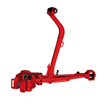
Power tongs are used on drilling rigs to rotate and thereby connect together (“make-up”) or disconnect (“break-out”) threaded connections between adjacent tubular segments in a tubular string. The tongs typically grip a first tubular segment and rotate it relative to a second tubular segment to either make-up or break-out the connection therebetween. FIG. 1A is a perspective view of an example of such a power tong 100. The power tong 100 includes a drive motor that may be hydraulically-powered (although a variety of other power-sources could be used) and a gripping assembly coupled to the motor 110 for gripping and rotating a tubular segment received within a bay 106. A generally “c-shaped” gear housing 112 supports a pivoting door 114. The door 114 may be closed to secure the bay 106 or swung open (as indicated in FIG. 1) to provide access to the bay 106. The bay 106 is generally surrounded by the housing 112. The center of the bay 106 is between a pair of generally opposed, pivotable gripping jaws 120, each having a generally arcuate gripping surface facing radially inward toward the center of the bay 106.
Manufacturer specifications typically call for high torque to properly make-up connections, e.g., on the order of thousands, up to tens of thousands of ft-lbs of torque. The components of a power tong thus are capable of producing and sustaining such high torque loads to rotate tubular segments to full make-up torque. As such, safely and effectively handling tubular members within an oilfield environment is a priority.
Further, issues with connecting together the joints arise, such as cross-threading. Typical casing and production tubing threaded connections are tapered, meaning the male threaded connection resembles a shallow tapered cone and the female threaded connection is also conical in shape to match the male threaded connection. Alignment of the male connection on the end of an add-on joint of tubular with the mating female connection takes place with a full length of add-on casing hanging vertically in the derrick. Any bend in the add-on joint of casing or lateral misalignment between the add-on joint and the female threaded connection at the top of the string can result in cross-threading of the male threaded connection relative to the female connection. Cross-threading is identified when the tong operator attempts to rotate the add-on joint, as a cross-threaded joint resists rotation immediately. By contrast, a properly threaded joint rotates several revolutions with ease until the conical male threaded connection approaches full make-up into the female threaded connection.
Once a cross-threaded connection is identified, the remedy is to back the add-on joint out in order to reposition the joint into proper alignment with the female threaded connection. Backing-out takes place by reversing the direction of operation of the power tong. Initially this involves rotating the gripping elements of the power tong to establish a grip between the power tong jaws and the add-on tubular in the opposite (back-out) direction. Once the grip is established in the back out direction, the power tong rotates the add-on joint in a break-out direction (e.g., counterclockwise) to free the male connection of the add-on joint from the female connection at the top of the string.
As shown in FIGS. 1B and 1C, reversing the power tong 100 from a make-up direction to a break-out direction of operation involves repositioning of the power tong 100 and an associated snub line 150. The snub line 150 secures the tong 100 against rotation in at least one direction, e.g., counterclockwise, which prevents movement of the tong 100 during make-up operations. When the tong 100 is reversed, e.g., to break-out a cross-threaded connection, care must be taken to avoid injury to an operator 160 caused by the tong 100 quickly reversing rotation, since the snub line 150 may not prevent rotation of the tong 100 toward the operator 155. If the reversal and repositioning of the tong 100 is done with haste and the power tong 100 is not properly secured against rotation when attempting to back-out the add-on joint, the power tong 100 can rotate towards the operator 160, and may strike the operator 160, potentially severely injuring the operator 160.
Embodiments of the present disclosure may provide a control system for a tong for a drilling rig. The control system includes a tong motor control valve that is selectively actuatable to cause rotation of the tong in a first direction or in a second direction, a run/pull mode selector configured to actuate between a first configuration for running tubulars into a well and a second configuration for pulling tubulars from the well, a rotation speed selector configured to actuate between a high-speed setting configured to cause the tong to be driven to rotate at a first speed, and a low-speed setting configured to cause the tong to be driven to rotate at a second speed, the first speed being greater than the second speed, and a rotation change control device configured to selectively prevent or permit actuation of the tong motor control valve based on whether the run/pull mode is in the first configuration or the second configuration and whether the rotation speed selector is in the high-speed setting or the low-speed setting.
Embodiments of the disclosure a method for controlling a tong including receiving a signal representing that a run/pull mode selector is in a first configuration associated with running tubulars into a well, and receiving a signal representing that a rotation speed selector is in a high-speed setting. The tong is configured to rotate at a first speed when the rotation speed selector is in the high-speed setting. The method also includes automatically permitting actuation of a tong motor control valve to cause the tong to rotate in a make-up direction, and automatically preventing actuation of the tong motor control valve to cause the tong to rotate in a break-out direction that is opposite to the make-up direction, until receiving a signal representing that the rotation speed selector has been actuated to a low-speed setting. The tong is configured to operate at a second speed that is less than the first speed when the rotation speed selector is in the low-speed setting.
Embodiments of the disclosure may also provide a tong including gripping jaws configured to grip a tubular, a motor configured to rotate the jaws and thereby rotate the tubular in either a make-up direction or a break-out direction, and a control system in communication with the motor. The control system includes a tong motor control valve that is selectively actuatable to cause rotation of the tong in a first direction or in a second direction, a run/pull mode selector configured to actuate between a first configuration for running tubulars into a well and a second configuration for pulling tubulars from the well, a rotation speed selector configured to actuate between a high-speed setting configured to cause the motor to drive the tong to rotate at a first speed, and a low-speed setting configured to cause the motor to drive the tong to rotate at a second speed, the first speed being greater than the second speed, and a rotation change control device configured to selectively prevent or permit actuation of the tong motor control valve based on whether the run/pull mode is in the first configuration or the second configuration and whether the rotation speed selector is in the high-speed setting or the low-speed setting.
FIG. 6 illustrates a side, cross-sectional view of a tong motor control valve, a rotation change control device, and a piston position sensing device of the control system, according to an embodiment.
FIG. 2 illustrates a functional block diagram of a control system 200 for a tong for a drilling rig, according to an embodiment. The tong may be the tong 100 discussed above or any other tong used to rotate one tubular relative to another and thereby connect and/or disconnect the tubulars on a drilling rig. The control system 200 may be configured to control either or both of rotation and speed of the tong 100 in a manner that automatically prevents uncontrolled movement of the tong housing, which, as mentioned above, presents a hazard to rig personnel and/or equipment if not prevented.
The system 200 may include a run/pull mode selector 202, a rotation speed selector 204, a directional control valve 205 (“directional” refers to the type of valve, not necessarily rotation direction), a rotation change control device 206, a low-speed indicator device 207, a tong motor control valve 208, and a piston position sensing device 212. These components 202-212 may be configured to control the rotation direction and speed of the tong 100.
In particular, the run/pull mode selector 202 may be a switch that is configured to be set in a run or pull mode (referred to herein as “configurations”) by a user/operator. The rotation speed selector 204 may likewise be a switch and may be configured to receive a high or low-speed setting from a user. The low-speed indicator device 207 may be configured to detect when the tong 100 is operating in the low-speed setting (e.g., when the rotation speed selector 204 is in the low-speed setting, and the tong has implemented the low-speed setting). The directional control valve 205 may be configured to control a speed range setting of the rotation of the tong 100, e.g., by interfacing with a gear shift cylinder that controls selection of a gear in a gear box (e.g. high gear and low gear), and thereby implement, if allowed, the speed setting of the rotation speed selector 204.
The tong motor control valve 208 may be a lever, joystick, slide, knob, etc. that is actuatable to cause the tong to rotate in a first or “make-up” direction and a second or “break-out” direction. For example, moving the tong motor control valve 208 in one direction may cause the tong 100 to rotate in the first direction, and moving the tong motor control valve 208 in the opposite direction may cause the tong 100 to rotate in the second direction. Further, the speed of rotation may be proportional to the degree of movement of the tong motor control valve 208 within two ranges, one high speed range, and one low speed range, corresponding to the high and low speed settings received using the speed selector 204 and the corresponding high and low gears engagements in the gear box.
The rotation change control device 206 may selectively permit or block actuation of the tong motor control valve 208 in response to signals provided thereto which are determined in part by control logic. The control logic receives inputs from the selectors 202, 204, along with inputs provided by system condition sensors, e.g., the low-speed indicator device 207 and the piston position sensing device 212, both of which interface with the directional control valve 205. The directional control valve 205 interfaces with a gear shift cylinder that selectively alters engagement of the gears within the tong 100 between high and low speed arrangements.
Accordingly, the system 200 may provide an interlock which selectively permits or blocks the tong motor control valve 208 causing rotation of the tong 100 in one or both rotational directions. For example, actuation of the tong motor control valve 208 may be blocked or permitted based at least partially on the configuration of the mode selector 202, the setting of the speed selector 204, and the determination by the low-speed indicator device 207. For example, as will be described in greater detail below, the components 202, 204, 205, and 207 may cooperate, e.g., as part of an electrical, pneumatic, or hydraulic circuit, to position blocking devices, e.g., pistons that selectively engage or disengage from a spool of the rotation change control device 206. When engaged, the pistons may block movement of the spool, and when disengaged, the pistons may permit movement of the spool. In turn, actuation of the tong motor control valve 208 may be permitted or blocked by permitting or allowing movement of the spool via the pistons.
In some embodiments, a user may attempt to cause the tong motor control valve 208 to change the direction in which the tong 100 rotates. For example, during running operations, the run/pull mode selector 202 may be in the run mode when cross-threading is detected. Thus, reversing the direction of rotation to break-out a cross-threaded operation may be desired, e.g., without changing the configuration of the mode selector 202 to the pull (as running operations may support backing out cross-threaded connections, for example). The system 200 may be configured to permit such rotation reversal, while allowing the tong run/pull mode selector 202 to remain in the run mode, but in a safe manner that prevents hazards, such as the tong 100 impacting the operator, as described above.
Thus, among other things, the system 200 may be configured to automatically prevent rotation of the tong 100 in the break-out direction when the tong 100 is configured in “run” mode and is in the high-speed setting, only allowing such rotation after actuating the rotation speed selector 204 to the low-speed setting, and, e.g., confirming such actuation has been implemented using the low-speed indicator device 207. In some embodiments, the tong 100 may likewise be prevented from reversing rotation while in the high-speed setting when in the pull mode. In some embodiments, the piston position sensing device 212 may prevent the tong 100 from actuating back to the high-speed setting, even upon the rotation speed selector 204 being actuated to the high-speed setting, at least until the tong 100 has been shifted into a neutral position, in which the tong 100 is not driven to rotate. In some embodiments, blocking the speed from changing may only be active when the tong 100 is in run mode, as other safety devices may be employed in the pull mode (e.g., the snub line).
With continuing reference to FIG. 2, FIG. 3 illustrates a flowchart of a method 300 for controlling a tong (e.g., the tong 100), according to an embodiment. The method 300 may be implemented at least in part using the system 200. The method 300 may begin by configuring the run/pull mode selector 202, as at 302. As noted above, the run/pull mode selector 202 may have a first configuration (“run mode”) and a second configuration (“pull mode”). Configuring the run/pull mode selector 202 at 302 may include moving a switch from a neutral position, for example, or selecting a button, or leaving a switch in a present state, etc.
These inputs may configure a circuit that provides input signals to the rotation change control device 206, which in turn allows or blocks movement of the tong motor control valve 208. Based on the configuration of the run/pull mode selector 202, the method 300 may include determining the rotation direction configuration, generally referring to the type of operation in which the tong 100 is being used (“run” refers to deploying or “running” tubulars into a well, and “pull” refers to extracting or “pulling” tubulars from the well), as at 306. Considering first the run mode, the method 300 may determine the rotation speed selector 204 setting, as at 308. When the rotation speed selector 204 is in the high-speed setting, the method 300 may proceed to 310, where the rotation change control device 206 may permit the tong motor control valve 208 to cause the tong 100 to rotate in the make-up direction at the high-speed as at 310, but may prevent the tong motor control valve 208 from causing rotation in the break-out direction (opposite to the make-up direction), as at 312 while the tong is in high gear. As such, a change in rotation direction without an accompanying change in speed selection may be prevented by preventing actuation of the tong motor control valve 208.
Referring again to block 308, when the rotation speed selector 204 is set to low-speed, the method 300 may proceed to the rotation change control device 206 permitting the tong motor control valve 208 to actuate and cause the tong 100 to rotate in either the make-up direction, as at 314, or the break-out direction, as at 316. Accordingly, it is seen that the tong motor control valve 208 is allowed to change the rotation direction of the tong 100 from make-up to break-out when the speed selector 204 is in the low-speed setting. Thus, when the speed selector 204 is in the high-speed setting, in order to change rotation direction, the speed selector 204 may first have to be actuated to the low-speed setting (and, e.g., confirmed by the low-speed indicator device 207). The method 300 may be continuous, e.g., implemented using valves in a pneumatic circuit, and thus when the speed selector 204 changes setting from the high to low-speed, the method 300 may respond by taking the low-speed branch from block 308, and then allowing rotation direction change.
Similarly, referring again to block 306, when the run/pull mode selector 202 is in the pull mode, the method 300 may proceed to block 318, in which the rotation change control device 206 may react to the rotation speed selector 204 setting and selectively preventing or permitting actuation of the tong motor control valve 208. When the rotation speed selector 204 is in the high-speed setting, the method 300 may proceed to the rotation change control device 206 permitting the tong motor control valve 208 to cause the tong 100 to rotate in the break-out direction, as at 320, but preventing the tong 100 from rotating in the make-up direction, as at 322. Referring again to block 318, when the rotation speed selector 204 is in the low-speed setting, the method 300 may proceed to the rotation change control device 206 permitting the tong motor control valve 208 to cause rotation in the break-out direction, as at 324, and permitting the tong motor control valve 208 to cause rotation in the make-up direction, as at 326. Thus, reversing direction, in this embodiment, in either the run or pull mode, is permitted only when the speed selector 204 is in the low-speed setting.
FIG. 4 illustrates a flowchart of a method 400 for controlling speed selection of the tong 100, according to an embodiment. The method 400 may be implemented at least in part by the piston position sensing device 212 (FIG. 2), which may be, for example, a part of the pneumatic or electrical circuit that controls or otherwise implements the rotation change control device 206. In some embodiments, at least part of either or both of the rotation change control device 206 and/or the piston position sensing device 212 may be implemented using relays in an electrical circuit.
The method 400 may begin by determining that the rotation speed selector 204 is in the low-speed setting, as at 402. This may be accomplished by receiving an analog or digital electric signal, a pneumatic signal, a hydraulic signal, etc. The piston position sensing device 212 may be configured to prevent the speed selector 204 from being actuated from low to high-speed, e.g., without the tong 100 being set to neutral. The neutral setting for the tong 100 may be state of the tong 100 in which the tong is not hydraulically or otherwise being driven to rotate. Accordingly, the piston position sensing device 212, once recognizing that the speed selector 204 is in the low-speed setting at 402, may wait for a signal indicating that the tong is in neutral. If the neutral setting signal is not received, the method 400 may block actuation of the rotation speed selector 204 from the low-speed setting to the high-speed setting, as at 406. Once the signal that the tong is in neutral is received, the piston position sensing device 212 may permit actuation of the speed selector 204 to the high-speed setting, as at 408.
In the configuration illustrated, pressure is received from a source 508, through the valve 501A, a line 509, the piston position sensing device 212 (which will be described in greater detail below), via a line 511, a shuttle valve 512, and to the “bottom” (as illustrated in the schematic) of the directional control valve 500. Pressure is also routed directly from the source 508 to the directional control valve 500, which the directional control valve 500 routes to the bottom of the gear shift cylinder 502, driving a piston 504 therein upward, resulting in a retraction of the gear shift cylinder, and thereby a selection of, for example, a high gear in the tong speed controller 210.
The valves 501A, 501B may communicate with a first piston 516 and a second piston 518, which may be configured to selectively allow or block linear motion of a spool 520. The pistons 516, 518 and the spool 520 may at least partially form the rotation change control device 206, which may be coupled to the tong motor control valve 208. The pistons 516, 518 may default (e.g., be biased to) to a lowered position, in which the pistons 516 each block movement of the spool 520 in at least one direction. In an embodiment, when a pressure signal is present in line 517, the first piston 516 may be raised, allowing movement of the spool 520 to the right, allowing the tong motor control valve 208 to rotate the tong 100 in the make-up direction. When a pressure signal is present in line 519, the second piston 518 may be raised, allowing movement of the spool 520 to the left, and causing the tong 100 to rotate in the break-out direction. When both pistons 516, 518 are raised, the spool 520 may be freely movable, and thereby cause rotation on the tong 100 in either direction, without additional modulation of the valves 501A, 501B or the selectors 202, 204 associated therewith. This satisfies blocks 314 and 316 in FIG. 3.
For example, with the selectors 202, 204 (and thus valves 501A, 501B) in their illustrated positions, pressure is routed through the valve 501A to the valve 501B, and then through a shuttle valve 522 to the first piston 516. This may raise the first piston 516, thereby allowing the spool 520 to move in at least one linear direction, e.g., right, as shown, from the illustrated neutral position. Allowing the spool 520 to move may allow for actuation of the tong motor control valve 208, in this case, to cause the tong 100 to rotate in the make-up direction. In this configuration, pressure is not routed to the second piston 518, and thus actuation of the spool 520 to the right is blocked by the second piston 518. This prevents actuation of the tong motor control valve 208 in the break-out direction. Accordingly, blocks 310 and 312 of FIG. 3 are satisfied.
When the rotation speed selector 204 is actuated to the low-speed setting, the valve 501A associated therewith changes position. As such, pressure is routed from the source 508, through the valve 501A, to the top of the pilot-actuated directional control valve 500, causing the pilot-actuated directional control valve 500 to actuate from its illustrated state and instead route pressure to the top of the gear shift cylinder 502. This drives the piston 504 downward, resulting in a low gear selection by the tong speed controller 210.
This selection actuates the valve 530 of the low-speed indicator device 207, e.g., via the mechanical linkage. The valve 530 may then route pressure through a shuttle valve 532 to the second piston 518, which raises the second piston 518. The raised second piston 518 may allow the spool 520 to translate to the left (as illustrated). Further, pressure may be routed from valve 501A to the first piston 516 via the shuttle valve 522, which causes the first piston 516 to lift away from the spool 520. As such, the spool 520 is able to actuate freely. Accordingly, with the run/pull mode selector 202 in the run mode, and the speed selector 204 in the low-speed setting, the tong motor control valve 208 may be movable to cause rotation in either direction, thereby satisfying blocks 314 and 316 from FIG. 3.
Accordingly, when a user attempts to actuate the speed selector 204 directly to high-speed, without first bringing the tong 100 to neutral (e.g., allowing both of the pistons 516, 518 to lower) the system 200 may not implement the gear shift. As shown in FIG. 5, the valve 501A is shifted to the high-speed setting, which directs pressure to the piston position sensing device 212, where it is blocked from reaching the shuttle valve 512 (or the directional control valve 205 beyond). Further, the shuttle valve 532 blocks pressure routed through the low-speed indicator device 207 from reaching the shuttle valve 512 or the pilot-actuated directional control valve 500. As such, until the piston position sensing device 212 is opened, which occurs when the second piston 518 is lowered, the actuation into the high-speed setting is prevented.
In the illustrated embodiment, when the valve 501B is in the opposite configuration to what is shown, i.e., in the pull mode, pressure is routed to a line 550. The line 550 may bypass the piston position sensing device 212 and provide pressure to the bottom of the pilot-actuated directional control valve 500, allowing the shifting of the valve 500 to the high-speed position, even if the piston position sensing device 212 is closed. As such, in this embodiment, when the system 200 is in the pull mode, the system 200 may permit actuation of the speed selector 204 from low to high, without first returning the tong 100 to neutral and allowing the pistons 516, 518 to fall. This may be permitted because other safety devices, such as snub lines, as described above, may prevent injury to an operator shifting to high in the pull mode. However, in other embodiments, the line 550 may instead route through the piston position sensing device 212 or a valve controlled by the position of the first piston 518, so as to further ensure safety of rig personnel by preventing direct speed shifting from low to high in the pull mode.
FIG. 6 illustrates a side, cross-sectional view of the tong motor control valve 208 and the rotation change control device 206, according to an embodiment. The tong motor control valve 208 may be selectively actuatable (e.g., manually, by operation of a user) to cause the tong 100 to rotate in either the first or second direction, and such selective actuation may be blocked or permitted via the rotation change control device 206.
As shown, the valve 208 may include a first housing 600 through which a spool 602 is received. A lever arm 604, which may be manipulated by a user, couples to the spool 602, and movement of the arm 604 left or right causes translation of the spool 602 within the first housing 600. The first housing 600 also includes an input port and two output ports 608, 610. Accordingly, the spool 602 may be translated from left-to-right to selectively allow communication between the input port and the output ports 608, 610, which are connected to respective ports of the tong motor. For example, when slid to the left, the spool 602 may permit communication through the first housing 600 between the input port and the output port 608 and through the motor port to which it is connected, while permitting fluid flow through the output port 610 to a return line. This results in the tong 100 rotating in the break-out direction. When slid to the right, the spool 602 may permit communication through the first housing 600 between the input port and the output port 610, while directing fluid flow from the output port 608 through a return line. This results in the tong 100 rotating in the make-up direction.
The illustrated embodiment of the rotation change control device 206 may include a housing 620 (referred as a “second” housing for contrast with the first housing 600), which may be coupled to the first housing 600. The second housing 620 may receive the spool 520 therein (the spool 602 may be referred to as a “first” spool, and the spool 520 may be referred to as a “second” spool, but this naming convention is merely to precisely identify the two spools, not to imply that one requires the other). The second spool 520 may be configured to move with the first spool 602. Further, if the second spool 520 is blocked from movement in one or both lateral directions, the first spool 602 may likewise be blocked. Blocking the first spool 602 may, in turn, block actuation of the tong motor control valve 208.
Further, the second housing 620 may include first and second signal ports 630, 632. The first port 630 may communicate with the line 517 (FIG. 5), and the second port 632 may communicate with the line 519 (FIG. 5). Thus, as described above, when a pressure signal is present at the line 517 and the first port 630, the pressure raises the first piston 516, thereby allowing actuation of the second spool 520 to the left, and likewise allowing movement of the first spool 602 to the left, which causes the tong to rotate in the break-out direction. Likewise, when a pressure signal is present at the line 519 and the second port 632, the pressure raises the second piston 518, allowing movement of the second spool 520 and the first spool 602 to the right, which allows the tong motor control valve 208 to cause the tong 100 to rotate in the make-up direction.
The illustrated embodiment of FIG. 6 also includes the piston position sensing device 212, which is formed as a third housing 640 coupled to the second housing 620. The third housing 640 may form an input port 642 that communicates with the line 509 (FIG. 5), and an output port 644 that communicates with the line 511 (FIG. 5). When the piston 518 is raised, an extension 646 of the piston 518 blocks communication between the input port 642 and the output port 644. When the piston 518 is lowered, communication therebetween is permitted. Thus, since the piston 518 is raised when the speed selector 204 is in the low-speed setting, actuation of the speed selector 204 from the low-speed setting to the high-speed setting is only permitted when pressure is relieved in the system, e.g., the piston 518 is lowered.
A linkage connects together the gear shift cylinder 502 and a tong gear change mechanism. The tong gear change mechanism may include a shift shaft 700, movement of which may shift gears in the tong gear change mechanism. The linkage may include one or more rods, brackets, braces, etc. For purposes of illustration, the present embodiment includes a guide shaft 702 and an indicator shaft 704, which are coupled together. Further, the input shaft 702 is also coupled to the gear shift cylinder shaft, so as to be movable vertically therewith. The output shaft 704 is also coupled to the shift shaft 700 via a toggle mechanism 720. Accordingly, movement of the gear shift cylinder output shaft downwards (e.g., to a low-gear position) in response to the selector 204 being moved to the low-speed setting may cause the guide shaft 702 to move downwards. This downwards movement is also transmitted to the indicator shaft 704, which in turn the shift shaft 700 to move upwards. When the selector 204 is actuated to the high-speed setting, the gear shift cylinder 502 moves upward, and the shafts 702, 704 move the shift shaft 700 downwards, thereby shifting to the high gear setting.
In addition, the indicator shaft 704 may contact an actuator 710 of the low-speed indicator device 207 when the gear shift cylinder 502 is in the low-speed position (i.e., moved downward from the position illustrated). When contacted, the actuator 710 may shift the valve 530 from its default position (illustrated in FIG. 5), to the opposite position, which may confirm that the tong 100 is being operated in the low-speed setting.
FIG. 8 illustrates a flowchart of a method 800 for controlling a tong, e.g., the tong rotation and/or speed, according to an embodiment. The method 800 may include receiving a signal representing that a run/pull mode selector is in a first configuration, as at 802. The tong may be configured to rotate primarily in a first, make-up direction when the run/pull mode selector is in the first configuration, but may, under certain conditions, be permitted to rotate in a second, break-out direction, e.g., to address cross-threading.
The method 800 may also include receiving a signal representing that a rotation speed selector is in a high-speed setting, as at 804. The tong is configured to rotate at a first speed when the rotation speed selector is in the high-speed setting. The method 800 may also include automatically (e.g., without intervention by a human operator) preventing rotation of the tong in the second direction until receiving a signal representing that the rotation speed selector has been actuated to the low-speed setting, as at 806. In an embodiment, the method 800 may also include receiving a signal representing that the rotation speed selector is in (e.g., has been actuated to) a low-speed setting, as at 808. In response, the method 800 may proceed to automatically permitting rotation of the tong in the second direction, as at 810. Permitting actuation at 808 may include actuating a low-speed indicator device in response to the rotation speed selector being in the low-speed setting. In an embodiment, actuating the low-speed indicator device is performed using a mechanical linkage between a gear shift valve and the low-speed indicator device.
The method 800 may also include preventing actuation of the rotation speed selector to the high-speed setting, while the tong is operating in the low-speed setting (e.g., in response to receiving the signal that the rotation speed selector is in the low-speed setting), as at 812. The method 800 may also include permitting actuation of the rotation speed selector to the high-speed setting in response to receiving a signal representing that the tong is in a neutral setting.
In one specific embodiment, the method 800 may further include blocking the execution of the rotation speed selectors output commands in response to receiving signals from the interlock system that the tong is operating in either the make up or break out direction. Accordingly, preventing rotation in the second direction may include blocking the spool from moving in at least one direction using a second piston in a lowered position. The method 800, may include moving at least one of the first or second pistons to permit movement of the rotation change control device in response to signals from the interlock system that the tong motor control valve is in the neutral condition.


 8613371530291