
power tong snub line price

The tong should be secured for both make-up or break-out operation, by utilizing the snub line. If this is not done, the tong may be thrown against operator causing physical harm.
When using the mechanical shift lever to change speeds, the power tong must first come to a complete stop before shifting. When using tongs hydraulic shift two-speed motor to change speeds, the tong may be shifted "On the Run."
Eckel tongs have proven to basically to last forever with minimal maintenance as all they are manufactured with the highest quality of steel. Using Eckel equipment tells your customer that you have the highest quality equipment on the market.
Tong size is determined by range of tubulars you will run. For example a 5-1/2 Hydra-Shift® is capable of running tubulars 5-1/2-inches and smaller while the 14 UHT is capable of running tubulars 14-inches and smaller. It is important not to use a large range of sizes with just one tong. If you have a 10-3/4 Standard and you regularly run 4-1/2-inch tubing with this tong, you might consider using a smaller tong.
PSI pressure determines the maximum torque the tong will safely be able to reach. Eckel rates all their tongs at the industry standard 2500 PSI. A competitor with a similar size tong may show more or the same torque as an Eckel tong due to a higher PSI from the power unit (which is in fine print) in an effort to fool you, thinking there tong is equal to the industry standard (Eckel tong.)
Gallons Per Minute determines the rotational speed of the tong. A low GPM will cause the tong to operate at a lower speed while a high GPM will result in the tong to rotate at a higher speed. Eckel offers an RPM (Revolutions per minute) Control which is a flow divider to decrease the amount of hydraulic fluid that reaches the tong if needed, the remaining fluid is returned to the power unit reservoir. By decreasing the amount of fluid reaching the tong the operator is able to control the maximum RPM of the tong.
Field tests have shown depending on several factors most power units used in above 32 degrees Fahrenheit conditions no matter if your hydraulic oil tank holds 200 gallons of oil, will exceed 150 degrees during a short 8 hour job. Most power units without hydraulic oil coolers exceed 170 degrees which is way past the recommended guide lines.

This website is using a security service to protect itself from online attacks. The action you just performed triggered the security solution. There are several actions that could trigger this block including submitting a certain word or phrase, a SQL command or malformed data.
Wire rope, one end of which is fastened to the end of a pipe tong handle attachment point and the other end secured to hold the tong stationary while the tong is in use.

One application of the rig tong is to use to make up connection. The question is asked about how to get the right torque value to the connection if you use the rig tong because you will not see the torque value on the gauge. This article will describe how to determine the correct force applied to get the correct torque value when you use the rig tong to make up the connection.

Well pipe is made up by supporting a lower pipe section ("joint") in the well and then threading an upper joint onto it by means of a fluid-driven power tongs. The pipe assembly is lowered as new joints are added, down to depths of several miles. Threaded well joint connections, in order to seal properly and to have maximum tensile strength, must be accurately tighted ("made-up" in the trade) to a design torque ("make-up torque") specified by the pipe manufacture. The design torque must not be exceeded, since galling or breakage of the pipe threads may result. This is particularly true with pipe joint materials chosen for considerations other than strength, e.g. corrosion resistance and impermeability. Such materials are not only relatively soft--they can be quite expensive. In one recent case, 1000 joints (each thirty-three feet long) were removed from a well. Every joint had thread damage due to overtorquing and was considered scrap. This was pipe originally costing $2500 per joint. The importance of controlling the torque applied by the power tongs to the pipe can thus be appreciated, and in fact it is a requirement on many jobs that a running record of maximum torque at each joint be kept. (Various systems exist for making torque records during make-up, including applicant"s system described in copending application Ser. Nos. 487,048.Iadd., now U.S. Pat. No. 4,552,041, .Iaddend.and 526,611.Iadd., now abandoned.Iaddend..) Despite the existence of accurate torque recording systems, improper torquing continues to occur. The industry still seeks a system that will positively prevent thread damage from overtorquing.
The crossed thread problem is aggravated by violent or jerky movement of the tongs when power is first applied. The tongs frequently do not work smoothly--and are hard to control--at very low speeds. Also, the snub line, initially slack, tends to snap tight when power is first applied. These conditions make it difficult to control and/or record torque at the instant tongs operation begins, so that thread damage can occur even if a low-level torque limiter is used.
I have found that the above problems can be overcome by substantially increasing the overall gear reduction ratio within the tongs, for example, by a factor of five. The tongs jaw speed is correspondingly reduced, avoiding the problems of irregular start-up. This speed reduction is advantageously combined with a two-stage torque limiter system for (a) preventing the application of substantial torque during the initial phase of makeup and (b) limiting the maximum torque that the tongs can produce at the final makeup stage.
Torque is automatically controlled during both tightening stages. In the initial stage, thread damage in the event of cross-threading is prevented by maintaining a very low torque cutoff point. In the final tightening stage, galling and breaking of threads is prevented by slowly turning the pipe 4 and automatically disabling the pipe tongs when a predetermined torque level is reached.
Another object is to enable the operator to control both the maximum obtainable tongs torque and the tongs speed during the final stage of connection makeup.
The preferred embodiment of the invention is illustrated diagrammatically in FIG. 1. The major components are a conventional hydraulic power unit A, a power tongs T driven by fluid from the power unit, a tongs sensor/recorder B and a torque control module C.
The power unit A, as shown in FIG. 1, comprises an internal combustion engine 10, a hydraulic pump 12 driven thereby, a pressure regulator 14 downstream of the pump, and a fluid reservoir 16 upstream of the pump. In operation, the power unit delivers pressurized fluid through high pressure line 20, and receives fluid exhausted by the tongs via return line 22.
The tongs T have both conventional and novel aspects. A conventional body 30 supports rotary jaws 32 adapted to engage the outside diameter of a pipe P. The body houses a gear train, details of which are not shown, including a two- or multi-speed transmission. Tongs of this type are well known. The transmission is manually shifted by means of a gear selector 34, with the ratio between high and low speeds being on the order of 4:1. The tongs are powered by a hydraulic motor 36 driving through two planetary gear reduction units 38 and 40 (FIG. 2) in series, each having about 51/2:1 reduction ratio. Further speed reduction is provided by spur gearing within the tongs body, so that the overall reduction is about 60:1 in high gear and 250:1 in low gear.
The tongs motor 36 is driven by fluid from the power unit, which enters the tongs via inlet line 42 and returns via exhaust line 44. A reversing shunt valve 46 on the tongs connected between the inlet and exhaust lines allows fluid to bypass the motor entirely when the valve is open. The shunt valve, normally open, may be moved to drive the tongs motor in either direction by a manual throttle handle 50 accessible to operator.
Any torque applied to the pipe P by the tongs creates a reaction torque that tends to rotate the tongs around the pipe. This tendency is restrained by a snub line 54 connected between a stationary object and the tongs body along a tangent line as shown. The snub line 54 includes two load transducers in series for monitoring tongs torque. The first transducer 56 is an on-off pneumatic valve having adjustable spring bias. This valve opens when tension corresponding to a preset "hand-tight" torque in the rage of 0-50 ft. lb. is applied. A manual override valve 58 in series with the first transducer 56 provides means by which the operator can disable the hand-tight torque control system, if desired.
An important feature of the invention is the on-off valve 60 mechanically connected via linkage 62 to the gear selector lever 34, such that the valve 60 is open only when the tongs are in their high-speed range, as shown. As a result, the transducer 56 performs its torque limiting function only during the initial, high speed phase .[.of.]. .Iadd.to .Iaddend.tongs operation, and does not interfere with high torque operation during the final stage of makeup.
The snub line 54 also has mounted therein a second load transducer 61 which communicates via conduit 62 with a Bourdon tube 64 supported within the recorder module B. The free end of the Bourdon tube is connected to the stylus 65 of a conventional chart recorder 66 having a spring-driven motor 68. The stylus has a small blade 70 attached thereto capable of interrupting flow of air through a normally open air gap unit 72, which can be moved toward or away from the stylus by means of threaded support 74 to adjust the threshold makeup torque. The air gap unit is supplied with air regulated to a very low pressure, e.g. 5 psi, so as not to affect stylus position. The output signal is amplified and inverted by the pneumatic logic unit 76, details of which are shown in applicant"s copending application Ser. No. 526,611, the disclosure of which is incorporated by reference. The logic unit 76 thus generates a high pressure output in conduit 78--provided the second override valve 80 is open--when the stylus blade 70 enters the air gap as the tongs reach maximum makeup torque. Conduit 78 leads to one input of a two-way check valve 82, the other input of which is from the hand-tight transducer 56. A high pressure at either input is thus delivered via conduit 84 to a second pneumatically actuated shunt valve 86, which when actuated halts tongs operation.
The valve 60, first transducer 56 and shunt valve 86 together provide means for halting tongs operation at a preset hand-tight torque level. Lever 34, linkage 62 and valve 60 function as means for disabling this first means. This general terminology is used in the claims below. The second transducer 61, recording module B and shunt valve 86 comprise means for halting tongs operation at a preset .[.fuel.]. .Iadd.full .Iaddend.makeup torque level.
Turning to the torque control module C, it can be seen that the tongs exhaust line 44 is directly connected to return line 22, while the tongs inlet line 42 is variably regulated as to both pressure and flow rate. Fluid entering the module from supply line 20 first encounters a three-way pneumatically actuated valve 88, whose position is ultimately determined by the position of gear selector lever 34. In high gear, fluid is directed to line 90, which is regulated to very low pressure in the range of 25-200 psi by the adjustable pressure regulator 92, which relieves excess pressure back to the return line 22.
When the tongs are in low gear, and valve 60 blocks delivery of control pressure to valve 88, the supply line 20 is connected to a unregulated high pressure line 94 having therein a manually adjustable flow rate controller 96. This valve enables the operator to control maximum tongs speed during the final makeup stage, without affecting the maximum torque obtainable. The variable restriction 98 shunting supply and return lines 20 and 22, on the other hand, enables the operator to limit the pressure deliverable to the tongs. Maximum tongs torque can thus be limited, providing a measure of redundancy over the automatic control system defined between transducer 61 and shunt valve 86.
In operation, as a drill string is supported by slips or the like on a rig deck, a new joint is brought into mating contact with the next lower joint, Once the threads are engaged, the tongs operator, having placed the gear selector in high, throws throttle 50, thereby closing shunt valve 46 to apply regulated pressure from line 42 to the tongs motor, which rotates the pipe slowly at about twenty rpm hand tight. Note that compressed air passes through valve 60 to valve 88, which directs all hydraulic fluid flow past low pressure regulator 92, substantially limiting the torque capacity of the tongs. Furthermore, air pressure is supplied to first transducer 56. When the preset threshold snub line load is reached, air passes through transducer 56, override valve 58 and check valve 82 to open the second shunt valve 86 and automatically stop the tongs. In the event of improper thread engagement, this sequence of events disables the tongs before thread damage occurs, regardless of the operator"s attentiveness or reaction time, and corrective action can be taken. It is not necessary, with this system, to count turns of pipe rotation or the like.
Provided the connection is properly run up to hand tight, and the operator can see that the sealing shoulders have come into contact, he then places the gear selector lever in "low", automatically obstructing the high pressure control signal to the second shunt valve 86, which thereupon closes so that tongs operation can be resumed. Simultaneously, the valve 88 reverses position.[.,.]. so that fluid at full pressure is delivered to the tongs. Now developing high torque, the tongs rotate the pipe very slowly--at five rpm or less, and this speed can be regulated by means of valve 96--until the desired makeup torque is reached. At the present cutoff torque level, stylus blade 70 enters the air gap unit, causing logic unit 76 to deliver a high pressure signal to open the second shunt valve 86, thereby automatically halting tongs operation.
Torque range at 2200 PSI/15.2 MPA High gear 2,400 ft.lbs/3,254 Nm “Low gear 12,000 ft.lbs./16,272 Nm” Maximum RPM at 50 GPM/189 LPM High: 86 RPM Low: 17 RPM Hydraulic Requirements 50 GPM @ 1,000 PSI 189 LPM @ 6.9 Mpa 20 GPM @ 2,200 PSI 75 LPM @ 15.2 Mpa Length 47 inches/119.38 cm Overall Width 31 inches/78.74 cm Space Required on Pipe 8 inches/20.32 cm Maximum elevator diameter Unlimited (Tong comes off pipe) Center line of pipe to center line of anchor handle 34 inches/86.36 cm Weight (approximate) 1,050 lbs./476.7 kg

In making up a pipe string for an oil well, a series of sections or joints having threaded ends are assembled in series as the pipe progresses into the well. The threaded connections are made by rotating a pipe joint by means of power tongs while holding the next lower joint stationary. It is generally desirable and frequently required that some automatic means be provided to apply a predetermined torque to the joints since overtorquing can damage the threads particularly with some modern pipe materials chosen for characteristics other than strength. On the other hand, undertorquing can result in leakage or unintentional disassembly of the joints. In some makeup operations, it is required not only that makeup torque be closely monitored but also that a permanent record be made of the makeup torque at each threaded connection.
The prior art includes numerous hydraulic power tongs, many of which are in the public domain, of the type having a hydraulic motor connected via a gear train to a rotary member having jaws for gripping the pipe. There are various known ways of limiting power tongs torque. One approach is simply to limit the hydraulic pressure differential across the motor; knowing the pressure-torque relationship of the motor and the ratio of the gear train, a predetermined makeup torque can thus be achieved. This approach is illustrated in U.S. Pat. No. 3,719,237, for example. Another known approach, used in the present invention, is to physically connect a torque or load transducer to the tongs. U.S. Pat. Nos. 4,199,032; 4,305,472; 3,745,820 and 4,091,451 illustrate tongs that are restrained against rotation with the pipe joint by a so-called snub line in which a load cell is mounted. The output of the load cell may be hydraulic pressure, as in U.S. Pat. Nos. 4,199,032 and 4,305,472; or an electrical output may be produced, as in U.S. Pat. Nos. 3,745,820 and 4,091,451. To achieve tongs cut-off at a particular torque level, the transducer may be linked to hydraulic control means in the tongs" hydraulic drive circuit. U.S. Pat. No. 4,305,472 shows one approach employing a shunt valve which, when opened, allows fluid to bypass the tongs. This approach is taken in the present invention.
It is therefore an object of the invention to provide the industry with a power tongs control unit capable of reliably limiting applied tongs torque at a predetermined level, maintaining the variations from the desired torque from joint to joint to a very small figure, and making a graphic permanent record of makeup torque while avoiding the disadvantages of the prior art. To these ends the applicant has set out to create a system avoiding the complexities of prior systems, particularly avoiding complex computers, electronic modules and the like while still achieving the primary goal of reliable, accurate torque control.
To summarize the invention, a conventional power tongs is controlled by a system including a hydraulic snub line load transducer, the output of which communicates with a Bourdon tube load indicator or recorder, a limit switch positioned adjacent the Bourdon tube so as to be closed when a certain pressure is reached within the tube, and a solenoid actuated dump valve positioned between hydraulic lines to the tongs" hydraulic motor, the solenoid being electrically connected to a battery via the limit switch so that when the switch is closed by the Bourdon tube, the solenoid valve is opened, disabling the tongs. The limit switch is adjustably mounted relative to the Bourdon tube so that the threshhold pressure, and by inference a corresponding tongs torque, can readily be adjusted.
Another aspect of the invention is the provision of hydraulic means for maintaining substantial torque on the pipe after tongs operation has been halted. Such means comprises an adjustable choke in series with the shunt valve, between the tongs motor"s hydraulic lines, whereby a substantial pressure differential is maintained across the tongs motor even after the shunt valve opens.
As a further feature of the invention, there is provided an adjustable electronic timer which, once the solenoid valve has been opened by the closure of the limit switch, continues to energize the solenoid, thereby holding the valve open for a predetermined time period. This timer prevents dangerous reapplication of torque to the tongs immediately following the initial disabling of the tongs, yet automatically resets the shunt valve in its closed position after enough time has passed for the operator to disable the tongs manually.
A known prior art tongs system is shown in FIG. 1 as including a power tongs 10 having jaws 12 for engaging a pipe P. The tongs have a hydraulic motor 14 which is mechnically connected to the jaws for rotating the same by a gear train (not shown). The tongs are capable of developing several thousand foot pounds of torque; they are therefore restrained from rotating about the pipe by a snub line 16, one end of which is secured to a stationary support 18 and the other end of which is secured to the tongs.
To determine the torque being applied to the pipe by the tongs at any moment, a hydraulic load transducer 20 is connected in the snub line 16. This transducer includes a piston or the like which generates a pressure in a transducer conduit 22 that is proportional to the load in the snub line. This pressure is used to control tongs operation as described hereafter.
The motor of the power tongs is driven by high pressure hydraulic fluid generated at the power unit designated generally as 30. This unit includes an internal combustion engine 32, a reservoir 34 and a hydraulic pump 36 driven by the engine. High pressure fluid passes from the pump 32 via a high pressure hose 38 to the inlet of the tongs motor 14. A return hose 40 is connected between the outlet of the tongs motor and the reservoir 30, and a pneumatically actuated dump valve 42 is connected between the inlet and outlet to the motor. This valve is normally closed, but when opened, allows fluid from the power unit to bypass the tongs motor thereby halting the tongs. The structure described to this point is found both in the present invention and in U.S. Pat. No. 4,305,472 (which uses different reference numerals). This prior art patent also shows a pneumatic controlling device 44 responsive to pressure in the transducer conduit 22 which automatically applies compressed air from source 46 to line 48 when a predetermined tongs torque is reached to open the pneumatically actuated shunt valve 42 and thereby halt the tongs operation.
FIG. 2 shows a preferred embodiment of the present invention and the similarities of the overall system to that shown in U.S. Pat. No. 4,305,472, will be apparent. FIG. 2 illustrates a tongs 110 having jaws 112 and a motor 114 that is hydraulically connected by lines 138 and 140 to a power unit 130 having an engine 132, a reservoir 134 and a pump 136. A bypass valve 113 is located on the tongs between the lines 138 and 140. This valve may be manually opened or closed by operating a lever 115 thereon.
The tongs are restrained from rotating around the pipe P by a snub line 116 connected to a stationary support 118 at one end and to a hydraulic transducer 120 at the other, which has an outlet conduit 122. Parallel to the bypass valve 113, a shunt valve 142 is connected between the inlet and outlet lines to the tongs motor 114. Here there is divergence from the prior art in that the dump valve has a solenoid actuator 150 connected by a conductor 152 to one terminal of a switch 154. The other terminal of the switch is connected by a conductor 156 to one terminal of a dry cell battery 158. A ground line 160 completes the circuit. The switch has a projecting actuating finger 162 which when depressed closes the switch, and the end of this finger is positioned in proximity to the free, closed end of a Bourdon tube 164. The other end of the Bourdon tube is firmly supported by an enclosure 166 and is in fluid communication with the transducer output conduit 122 previously referred to. A conventional pressure gage 168 is also connected to the transducer output. It is preferred that the face of the gage 168 be calibrated to indicate the torque being applied by the power tongs and this calibration would of course require consideration of the transducer load-to-pressure relationship as well as the radial distance from the pipe P to the snub line 116.
In the preferred system the free end of the Bourdon tube 164 is connected by appropriate mechnical linkage 170, indicated schematically by a broken line, to the arm of a stylus recorder 172. As mentioned above, it is frequently required to make a running record of torque supplied as the pipe is assembled and the recorder provides a permanent record.
Another important aspect of the invention is the provision of means for holding the shunt valve open for a period of time sufficient for the tongs operator to manually deactivate the tongs. It will be appreciated that without this feature, the instant the dump valve was activated, and the tongs torque thereby released, the transducer pressure would go to zero, the Bourdon tube would retract and the switch 154 would open, possibly causing rapid, dangerous reapplication of full tongs torque in a rapidly cyclic fashion.
To avoid this problem, a timer is provided in the electrical circuit which functions to maintain the application of electrical power to the solenoid dump valve for a predetermined time after it is actuated, regardless of whether the switch 154 is opened or closed. This timer is preferably adjustable so that the mandatory tongs-off interval can be adjusted from, say, two to four seconds. Such an interval gives the operator sufficient time to deactivate the tongs manually, without disabling the tongs so long as to slow the makeup operation.
In operation of the device, the power unit 130 continuously operates, producing high pressure fluid in the quantities required for the tongs. The tongs are placed around the pipe P and the operator manually throws the lever 115 thereby closing the bypass valve 113 and applying full pressure to the tongs, which cause the pipe joint to rotate as it is threaded into the next section below. When the threads are nearly completely engaged, the torque rises rapidly as does the snub line tension and therefore the pressure in conduit 122. The Bourdon tube correspondingly distends, engaging the switch actuator 162 and eventually closing the switch 154. At this point electrical power is applied to the solenoid 150 opening the shunt valve 142 and causing the tongs torque to drop to zero. Once the switch is closed, the timer maintains the circuit between the battery and the solenoid in a closed condition for a period of time and during this time the operator manually opens the valve 113. Thereafter, at the end of the interval for which the timer is set, the circuit is reopened, closing the shunt valve 142 so that the operator upon throwing the handle 115 can initiate another operating cycle.
FIG. 3 illustrates an alternative embodiment of the invention which is somewhat simpler yet retains the inventive aspects of the system shown in FIG. 2. In this embodiment the recorder has been dispensed with and replaced by a simple pressure gage 268, preferably calibrated to show tongs torque. The pressure gage 268 includes a Bourdon tube 264, the distendible end of which is connected by suitable linkage to the gage pointer. The gage contains electrical elements corresponding to the FIG. 2 embodiment, specifically a switch 254 having a protruding finger 262 engageable by the free end of the Bourdon tube, the switch preferably having an adjustable threaded mounting means 274 as shown. As in the previous embodiment, the switch is connected by conductors 252,256 and 260 between a battery 258 and the shunt valve solenoid actuator 250. The remainder of this system is structurally identical to that of FIG. 2 and its operation is also similar.
FIG. 4 illustrates a modified form of the invention in which means are provided for maintaining substantial torque upon the pipe P even after the shunt valve 342 has been opened by the controller upon reaching the threshhold cutoff torque. The power unit is identical to that previously shown and the control mechanism may be as in either FIG. 2 or 3; therefore, only the portion of the system in the vicinity of the tongs is illustrated. As shown, the tongs 310 have a hydraulic motor 314 connected by hydraulic lines 338 and 340 to the power unit not shown. Between the lines 338 and 340, there is as before a manually operable bypass valve 313 and parallel to this valve also extending between the lines 338 and 340 is a shunt controlled by the shunt valve 342. What is different here is the addition of an adjustable choke 376 in the shunt in series with the valve 342. In operation the manually operable bypass valve 313 will have been closed by the operator to activate the tongs and the tongs will have rotated the pipe P into a fully madeup position. The pressure generated by the transducer 320 as this position was approached will have caused the controller (not shown) to activate the solenoid actuator 350 at the threshhold torque thereby opening the valve 342. At this point the manually operable bypass valve 313 is still closed so that fluid can avoid passing through the motor 314 only by passing through the shunt valve 342 and the choke 376. Without the choke, as previously mentioned, there would be substantially no resistance to fluid flow and the pressure differential across the motor 314 would be substantially zero. However with the choke 376 a substantial pressure differential can be maintained so that the tongs which have ceased rotation will still continue to apply torque to the threaded connections for a period of time. This feature desirably allows the threads to set and will provide increased uniformity in the effective madeup torque from joint to joint. The choke 376 is preferably adjustable whereby the torque level on the pipe following opening of the valve 342 can be adjusted as desired. This torque will of course be readable on the indicator used and will persist until the bypass valve 313 is manually opened by the operator. As in the other embodiments, the shunt valve 342 is held open by the timer sufficiently long to enable the operator to safely open the valve 313, whereafter the shunt valve 342 is automatically reset.
The tubular running process comprises the use of a tong to make up and break out connections. Over the years many different tong types have been developed, from manual tongs to fully mechanized power tongs. The torque reaction system in the tong plays an important role in providing optimum torque to the connection, which depends on how well it eliminates undesirable side forces on and bending of the connection. Side forces create high friction on the threads that can cause the measuring system to provide an incorrect torque reading, which can result in an undertorqued connection. The friction and compressive forces can also introduce thread galling problems that affect connection integrity.
To evaluate this phenomenon, laboratory tests were performed on a 5.50-in. premium connection joint using two power tongs with three different torque reaction systems (free-floating backup, integral backup, and snub line). Strain gauges and 3D-optical strain measurements were used to analyze forces and deflection acting on the connection during makeup. Results indicate higher side forces and bending on the connection when using integral backup and snub line configurations; however, the free-floating backup system reduces these forces significantly.
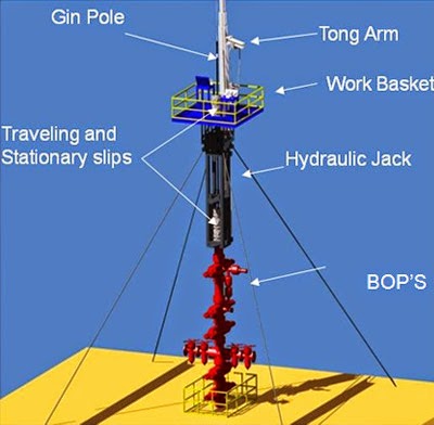
BOP stack: A series of blow out preventers stacked together using an equalizing and bleed of spool. Stack normally consists of an annular; equalize spool and a set of stripping rams. In snubbing operations the BOP stack is considered a secondary BOP. When working in conjunction with a workover, service or drilling rig the rig supplies the primary BOP’s.
Counter Balance Winches: A winch that can hydraulically counter balance the weight it is picking up. This gives the winch the ability to automatically feed off should the load placed upon it become greater than the actual weight being held via the hydraulics. Typically the snubbing unit will have two of these winches.
Equalize line: High pressure line pipe, chick sans (swivels) and valves for use during a snubbing operation to equalize or bleed off pressures within different chambers in a snubbing BOP stack.
Equalize spool: A ported spool for use in a snubbing operations allowing the operator the ability to equalize or bleed off certain sections of the BOP stack.
Gas well snubbing: Workover or completion work on a gas well which is either live or underbalanced with a rig assist or self-contained snubbing unit. Many gas well formations are fluid sensitive making a snubbing operation ideal for maximum production of the well. Eliminates the need for expensive kill fluids.
Guide Tube: Any arrangement of support system that prevents columnar buckling of the pipe being snubbed. Typical arrangements can be telescopic or static depending on the design of the snubbing unit structure.
Live well completions: A well condition where tubulars and tools are pulled or inserted into a well with the use of a rig assist snubbing unit or self-contained snubbing unit. The well has surface pressure from the down hole formations. Wells can be either gas or oil.
Live well workovers: Describes the condition of a gas or oil well is in when tubulars are snubbed in or out of well. There is pressure at surface in these wells making them ideal candidates for snubbing operations.
Lower snubbing basket: The work floor area which allows access to the snubbing crew to the BOP stack components and stationary snubbing and heavy slips.
Passive Rotary: A turn-table integrally mounted in the snubbing unit traveling plate which allows the rotation of the string with the slips closed on the pipe in either the snub mode or pipe heavy mode. This rotary must be driven with an external force be it by hand or with a power swivel rigged above the unit.
Pipe Heavy: In regards to snubbing, this is a pipe condition in which the tubing has sufficient string weight to overcome the forces acting on its cross-sectional area. Once the weight is sufficient, it overcomes the force applied by the pressure in the well and will fall under its own weight into the well.
Pipe Light: In regards to snubbing, this term describes the condition when the well bore forces acting on the cross-sectional area of the pipe being snubbed are greater than string weight; if tubing is not controlled, the snubbing unit will eject itself from the well.
Power-Pack: This is the prime mover that provides the force needed to turn hydraulic pumps which allow the operation of the snubbing jack and BOP systems. Diesel engines are the most common form, although electric drives are also utilized in special circumstances.
Powered Rotary: A turn-table integrally mounted in the snubbing unit traveling plate which allows the rotation of the string with the slips closed on the pipe in either the snub mode or pipe heavy mode. This rotary is driven with hydraulic motors, allowing the unit to perform string rotation without external support equipment.
Rig assist snubbing: A mobile snubbing unit, either truck-mounted or skid-mounted, that works in conjunction with a workover, service or drilling rig for workover or completions work on a live well or underbalanced well. Unit is capable of running or pulling tubulars and tools under pressure.
Scalloped spool: A spacer spool modified for snubbing to allow well bore pressures to equalize or bleed off around the tubing hanger when landing or pulling the hanger.
Self contained snubbing:A snubbing unit which stands alone by itself with no need of a service, workover or drilling rig. A self-contained unit is capable of workover or completion work on a live well or underbalanced well or indirect.
Snubbing: A procedure in which tubing is run or pulled from a well, which is in an underbalanced or live well condition. Snubbing units have specialized pressure control devices which permit them to deliver drilling, completion and workover services while there is pressure in the wellbore. Snubbing units eliminate the need to neutralize well pressure prior to servicing and therefore avoid the formation damage which neutralizing pressure can have on a well’s ability to produce.
Snubbing Assistant: This person’s position is primarily focused on taking direction from the snubbing operator, and entails routine maintenance, pipe handling and power tong operation.
Snubbing jack: The structure of the unit designed to withstand engineered ratings for both the pipe weight and the force applied by the unit’s hydraulic cylinders. The hydraulically operated equipment which enables crews to work on underbalanced or live well.
Snubbing Operator:Equivalent to a driller position, the snubbing operator physically operates the snubbing unit and takes direction from the snubbing supervisor. The operator is responsible for managing the daily activities of the rest of the snubbing crew, and ensuring that the equipment is functioning as designed.
Snubbing slips: A set of hydraulically actuated slips which can be run either inverted or right side up to control the movements of pipe in conjunction with a snubbing jack to insert or extract tubulars under live well or underbalanced conditions.
Snubbing Supervisor:Equivalent to a rig manager or tool push, the snubbing supervisor is responsible for all aspects of the snubbing unit and its operations. He/she is the direct liaison to the oil company representative he/she is working for. All members of the snubbing crew are subordinate to the snubbing supervisor. Typically the supervisor will have in excess of 10 years’ experience in snubbing operations.
Snubbing unit: A hydraulically actuated unit with slips, BOP stack and hydraulic jack for inserting or pulling tubing and BHA’s from underbalanced or live well conditions.
Stand alone snubbing (see self contained unit): Use of a snubbing unit by itself without the aid of a service, workover or drilling rig. Unit is capable of workover or completion work on a live well or underbalanced well.
Stationary snubbing slips: A set of snubbing slips that are typically mounted on top of a BOP stack which will hold pipe that is in a pipe light or neutral state.
Stripping: : During snubbing operations this is the procedure where you move pipe through a closed preventer (pipe rams or annular) on a live or underbalanced well containing pressure from the well bore with a closed preventer.
Stripping on: : The procedure in which a snubbing unit is rigged onto a service, workover or drilling rig, which is holding the pipe heavy tubing string with their tubing slips and not with a tubing hanger landed.
Stripping Ram: A hydraulically operated ram style BOP used during snubbing and stripping operations. Typically the ram front insert is a sacrificial material that is easily replaced for extended stripping. Materials for the inserts can be custom ordered for the application at hand.
TEP: A type of tubing plug developed for snubbing to control well bore pressures inside the tubing. Only viable for snubbing in operations. The plug is a machined collar with a removable disc and “o” ring. Once the tubing string has been snubbed in, the disc can be knocked out by equalizing the tubing string and flowing the casing. Once an overbalanced condition has been achieved inside the tubing string, the disc will fall out. Disc may also be removed by sand line or wire line tapping down on the disc once tubing string has been equalized with casing pressures.
Traveling plate: The plate which connects the rods from the hydraulic cylinders together on a snubbing unit where the traveling and heavy slips are attached. There are many cylinder configurations and stroke lengths possible depending on job requirements.
Traveling snubbing slips: A set of slips mounted upside down on a snubbing jacks traveling plate, which controls the movement of tubing in or out of a well. Slips will hold tubing only when tubing is in the pipe light state.
Underbalanced:A term to describe the pressure conditions in a well. Formation pressure is greater than the hydrostatic pressure of fluid, mud, etc… exerted on the formation causing pressure to migrate to surface in a well. A well in an underbalanced state is a prime candidate for snubbing.
Underbalanced completions: The condition of a well when completion services such as snubbing are performed. Formation pressure is greater than the hydrostatic pressure inside the well bore causing pressure to be at surface in the well. Underbalanced completions are prime candidates for snubbing. Typically wells have been perforated before snubbing unit arrives and the unit snubs in a production string to allow the well to be produced.
Underbalanced drilling: This term describes the condition of the well when drilling operations are ongoing. Snubbing units are used to snub out drill strings, i.e. bit changes and then snub in the drill string again or run productions strings.
Underbalanced workovers: The well is live with pressure to surface when workover operations are performed. Rig assist snubbing or self-contained snubbing units are used for the running or pulling of tubulars and BHA’s. Typically the snubbing unit pulls pipe from the well, the original zone is worked over, abandoned, or a new zone perforated and the snubbing unit snubs the production string back into the well.
Well control:In regards to snubbing, well control is the operation of containing well bore pressure with the use of a blowout preventer stack and tubing pressure by the use of a plugging system.


 8613371530291