
stepper motor rotary table free sample
Motorized worm gear driven rotary tables provide high angular resolution (the worm gear ratio directly multiplies the motor output torque and motor angle resolution) and holding torque. PI offers precision motorized worm gear rotary tables with both stepper motors and closed-loop servo motors with encoder feedback. While open-loop stepper motors are often used for their lower cost and ease of control, closed loop servo motors with encoder feedback provide higher speed, higher accuracy, and repeatability. PI also provides closed-loop stepper motor rotary stages, combining the best of both worlds. PI stepper motor rotation stages are provided with stepper motor controllers featuring a micro stepping mode for higher performance. For single axis applications, a compact and very cost effective single axis stepper motor controller is available.
For the best performance and highest velocity, direct-drive rotary stages with torque motors are recommended (link to new Rotary Stage Page with Direct Drive Torque Motors).
The DGII Series is a line of of products that combine a high rigidity hollow rotary table with an AlphaStep closed loop stepper motor and driver package. It retains the ease of use of a stepper motor, while also allowing for highly accurate positioning of large inertia loads.
AlphaStep products are stepper motor based hybrid motors with a unique hybrid control system combining the benefits of "open loop control" and "closed loop control".
By utilizing the high responsiveness of the stepper motor, moving a short distance for a short time is possible. The motors can execute commands without lag.
During positioning, the motor stops with its own holding force without hunting. Because of this, it is ideal for applications where the low rigidity of the mechanism requires absence of vibration upon stopping.
If an overload is applied continuously, an alarm signal is output. When the positioning is complete, and END signal is output. This ensures the same level of reliability as a servo motor.

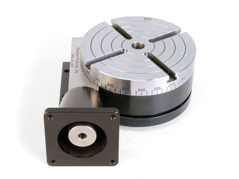
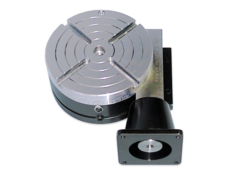
I am wondering how it would work to mount a stepper motor or servo motor on the rotary table. What all would I need in order to make a laptop computer operate the rotary table?Sherline makes a very small rotary table that is just what I am looking for but it is tiny. I need something bigger and stronger. The sherline looks like you can program a certain number of divisions and then every time you hit the button it moves to the next location.
Well, depends on your skills. You need to be able to design and machine a simple mounting plate, connect up wires to printed circuit board screw terminals, run some software, etc. Your immediate application doesn"t require maximum performance. Steppers should be ok, and you won"t need more expensive motors, controllers, and lots of fine tuning. Just don"t try to push the speed limits unless you know what you are doing.
Step 1: measure the amount of force it takes to turn the wheel, so you know what size stepper you need. Put some load on the table, like a heavy vise and pull the edge of table with 50+lbs of force (1/4 horsepower, scale up as needed) to simulate machining forces (although in your immediate app, you probably won"t be machining and moving at the same time). Give yourself a safety factor. A double ended shaft is recommended, so you can mount a handwheel on back end for manual operation. For a small table like the sherline, most NEMA-23 motors should work. For a larger one, you may need higher torque NEMA-23, NEMA-34, or geared steppers.
Gearing adds backlash - not a big deal if you are moving in only one direction as a simple indexer but a problem if you are doing more sophisticated stuff. If you need a motor that draws more than about 3A, drivers get more expensive.
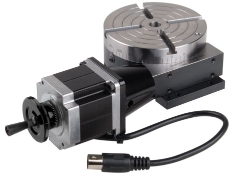
Step 2: physically mount motor to rotary table. On some tables, the shaft is supported on one end by a piece that bolts on. This provides convenient mounting. You may be able to machine a plate that has the original mounting holes, a bore for the bearing, and 4 holes for standoffs that match the stepper motor mounting holes. You will need a flex coupling. Bear in mind that the position of the shaft determines how well the gears mate and how much backlash there is. You may want slots for the mounting holes so you can slide the plate.
Step 3: stepper motor driver. These can be had easily on ebay and elsewhere. They usually have step and direction inputs. Should be able to handle your motor. There are some bare boards here if you can solder electronic circuits: http://www.pminmo.com/
Step 4: Power supply to match your motor driver. Most will let you use a voltage higher than the rated voltage of the motor. This gives much better performance. You can reduce the current rating of the power supply by roughly the ratio of the power supply voltage to the motor voltage. You may need up to twice as much because two windings may be energized at the same time. Power supplies can be had cheap on ebay. Wire to stepper motor driver board. Be careful NOT to ground the negative lead at the power supply (and don"t use a power supply that won"t let you float ground). Otherwise, the voltage drop accross the negative lead causes ground current loops which can be bad for your computer. Ground at the motor driver only.
Step 5: PC interface. If your laptop has a parallel port, all you need to do is connect ground, step, and direction. The latter two can be connected to D0 and D1 on the parallel port. You will configure the software to tell it what pins you used. Parallel ports are going the way of dodo birds. USB->Parallel adapters are not suitable. USB is a bit trickier, though there are some stepper controllers available: here is one: http://www.usbcnc.com/index_products.html. I have seen a cheaper one designed by someone here or on CNCzone that looked halfway decent but can"t find it at the moment. About EU$69, USB, PIC based, 3 axis, no source code, windoze software included. Looked adequate for what you are doing but not for my purposes:
Leave yourself some room to expand. Put a motor on your X axis, for example, and now the computer can cut your gear with a little programming and you have a power feed.
Our direct drive rotary tables provide high torque and are easy to integrate. They contain high-energy magnets in a simplified mechanical design and drive loads directly without the need for a transmission mechanism or gearbox. It allows customers to build them right into a drive system for flexible placement and integration with cooling pipes and cables, for example.
We supply a wide range of frameless motors, and our adjustable motors include an optical encoder, scale, bearing and housing. Given our selection, it can be challenging to choose the best direct drive motor for your project. Our engineers prefer to help you find the right rotary table for your requirements.
Our most popular rotary motor, the AXD series is characterized by a slim, compact "pancake" design with high peak and continuous torque despite the motor"s quite small form factor.Direct drive and brushless motor
The ACD series is a set of ironless rotary tables. This motor is cogging-free and features high-resolution optical encoder feedback and low speed variability. This permanent magnet motor is equally suited for either low or high speed applications.Zero cogging coreless motor
The ACW series features a cogless construction and lean design, with high-precision coding and ultra-precision bearings. Together, this results in our highest performing motor in terms of repeatability and smooth motion.Direct drive brushless motor
The ADR-A series is available with both low and high speed windings and is fully equipped with an encoder and bearing. This series has a high slot fill factor and generates very high torque.Direct drive brushless permanent magnet motor
The ADR-B range performs at a similar slot fill factor and torque density to the ADR-A range, but has a larger center hole compared to its equivalent.Direct drive brushless permanent magnet motor
Similar to the ACD series, the AXM series also features an ironless design and zero noise characteristics. This motor has a compact design, making it ideal for applications with specialized size requirements.Direct drive brushless permanent magnet motor
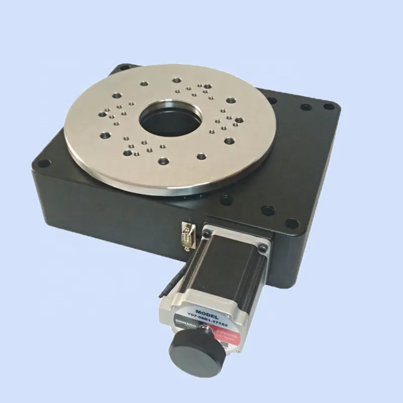
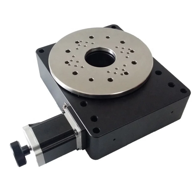
This compact closed-loop direct drive rotary table uses a 3-phase motor for maintenance free, frictionless power transmission. It comes in two variations, standard and with holding brake.
Application video of the silent ultrasonic piezo motor rotary stage in a Leica Theodolite and Principle Design of the PILine drive used in the M-660 PILine� rotary stage
This miniaturized closed-loop rotary positioner is driven by an ultrasonic direct-drive motor and provides high rotational velocity up to 3 revolutions / second. An optical encoder is integrated for direct position measurement and feedback with 35 �rad resolution.
A fast ultrasonic ceramic ring-shaped resonator motor provides high speed to 120 RPM. An optical direct metrology encoder is integrated for position feedback.
Q-motion series miniature rotation stages are driven by inertia-type piezo motors. These miniaturized positoining tables are direct-driven, backlash free and provide micro-radian resolution. The self-locking design requires no holding current and provides excellent long-term stability. Three different diameters are available: 14 mm, 22 mm and 32 mm.
The PI miCos line of goniometers and rotation stages is specialized on miniature stages with different motor drives (belt-drives, worm-gear drives) and also on ultra-high precision stages with torque motors, direct metrology and air bearings.
Goniometric cradles are used to rotate samples and objects to a precise angular position. The units here are equipped with precision servo and stepper motors and high-resolution encoders for angular position feedback.
Ultra-slow motion animation of the PILine� ultrasonic piezo motor. The ceramic tip (pusher) is moving on an pseudo-elliptical trajectory. In reality the tip only moves a few nanometers at frequencies to 100"s of kHz.

The stepper motor will have to be sized for your application. I used a small 3 rotary table and dont plan on using it for anything other than indexing so a high torque NEMA17 did the job. If youre working with a larger rotary table or want to be able to use it as a 4th axis in the mill you will want at least a NEMA23 size motor. You will have to reach out to the forum for help with selection.
Control digital devices and make machinery more precise with a stepper motor from Alibaba.com"s wholesale equipment store. Our catalogue is the place to come when you need a replacement stepper motor rotary table or any other motor related products. You"ll find a huge array of wholesale motors, including step motors with high torque ratings that can offer incredibly precise control. Whether you"re constructing an astronomical telescope or a digital network for broadcasting, these motors will do the job.
Stepper motors are used in situations where devices need to be calibrated to extremely high levels of precision. They aren"t always the most powerful motors, but they do have very high torque levels, and this allows them to control devices in ways that other motors cannot. And they also tend to work well with digital devices due to their "step" mechanism. For instance, you can find step motors in many hard drives, handling millions of operations every minute. They have also become a go-to motor style for robotics installations. So you might need one for an advanced production line. When you need a stepper motor rotary table, finding the right motor is easy. Just search Alibaba.com"s catalogue and you"ll easily find what"s required.
Our stepper motor collection covers every base. Browse motors for use with mini computers like the Raspberry Pi or models designed for use with Arduino components. Look for permanent magnet motors, variable reluctance steppers, or hybrid syncronous steppers, and models with micro step, half step, and full step modes. Our listings include everything you need to control the most complex systems. So find a stepper motor rotary table and order what you need today. Everything can be handled with a couple of clicks, putting specialist stepper motor components within easy reach.
Having used my 6 inch Vertex rotary for 2 years I wanted to find a better way to mount a chuck that didn’t consume unnecessary Z axis height and with the chuck removed also provide a platform for workholding that was more flexible than just 3 T slots. That went one step further (pun intended) with a desire to speed up manual operation. This is the result, which is as compact as I could achieve and prevents the often-seen massive overhang of the stepper motor hanging off an adaptor tube of some sort. The stepper driver and division controlleris from Steve at World of Ward which gives increments down to .01 degrees with standard stepper driver settings.
I have a strong dislike for unprotected wires as seen on many projects with stepper motors. By chance I found an existing 3D model for Nema 23 size motors that was downloaded for free and sent to a 3D printer bureau. This link will give you a choice of end covers and with a lock type multi-pin connector the electrical connection is robust and can be easily disconnected. **LINK**
A few examples of the work for my Bolton Marine triple are included. The rotary table together with the DRO fitted to my Tom Senior E type mill (see other album) helps me be both precise and confident enough not to have to mark one part from another. As for speed, a few seconds for an index and your back to drilling another hole.
The controller is from Steve Ward here https://www.worldofward.com/ You can buy a kit or purchase ready made. There is a download section for manuals etc if you wanted to take a look at some of the details. The controller includes a adjustable setting to take into account any backlash.
The controller is from Steve Ward here https://www.worldofward.com/ You can buy a kit or purchase ready made. There is a download section for manuals etc if you wanted to take a look at some of the details. The controller includes a adjustable setting to take into account any backlash.
Hi Ian, as above I downloaded the 3D model of the stepper end cover from here **LINK** this link will give you the available design options then I uploaded to a 3D printing service to generate the model. You can search for such services but here are links to 2 of them https://www.3dpeople.uk/ and https://www.hubs.com/3d-printing/united-kingdom/
I have previously designed & printed my own using 4-pin XLR connectors, the two motors I have, both same NEMA size, have diffeent mounting holes, but the one linked to seems to cover that option.


 8613371530291