
stepper motor rotary table pricelist
Stepper motor is an actuator that transforms the digital pulse signal into angular displacement. Namely, when stepper drive receives a pulse signal, it drives the stepper motor to rotate at a fixed angle (i.e. step angle) in the set direction. Stepper motor is a main executive component in the modern digital control system, and has a very wide range of applications because of the following advantages:
Long service life. Unlike DC motors, stepper motors don’t need to adjust phase position by the brush and commutator, thus reducing the friction and increasing the service life.
ATO offers a large number of high-quality stepper motor in different frame sizes for your selection, including Nema 17, Nema 23, Nema 24, Nema 34, Nema 42 stepper motors, micro stepper motors and linear stepper motors. The specific prices of ATO stepper motors are listed as below for your reference. Please kindly note that just part of ATO stepper motors are shown in the table below, not the all. For more information, please check the product page of stepper motors.
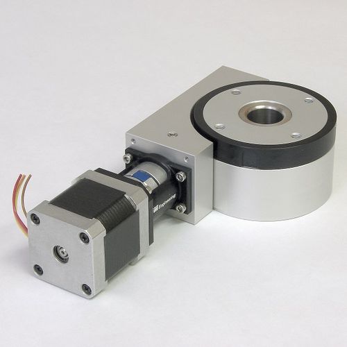
The MOR-215-70 motorized rotation stage uses the precision ground and hardened worm gear with self-compensating preload and precision crossed roller bearings. The precision ground worm gear produces consistent driving torque to the rotating carriage. The crossed roller bearings with high rotation accuracy are capable of bearing loads in every direction.
This motorized rotation stage is equipped with a hardware origin and allows for continuous rotation of 360°. The central aperture is 70mm. A hall effect sensor (as the zero position) is built in the rotation stage, so the top plate can"t move in a negative direction to pass over the zero position.
02 series motion controller can be used to control motorized stage with NEMA23 stepper motor. We have 220V and 110V power supply options for each motion controller. The USB line can be used to connect the motion controller to laptop. Please click following links to get more information.

Rotary Tables enables the motion systems to carry load maintainig accuracy and stability. The rotary teable brings smooth motion with low friction and greater range of rotary motion.

※ The scale ring on the periphery of the table top is a laser scribing scale, which can rotate relative to the table top to facilitate initial positioning and reading

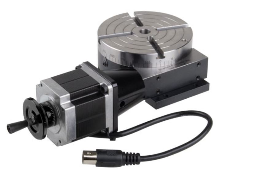
Sherline offers one of the finest small rotary tables on the market. It is available in manual or stepper motor drive modes. It can even be purchased with its one controller to be used as a programmable indexer.
can mount our chucks. This modification came about after requests from our laser engraving customers. The larger through hole allows for larger stock to be held. It also has a Nickel-Teflon plating on it because it was designed to be used in an every-day production environment. This gives the table a rust resistant surface that is hard and has added lubrication qualities.
Sherline�s rotary table offers an accurate, stable platform for rotary laser marking applications. Its compact size makes it a good fit in small enclosures. Visit our Video page to watch a Sherline CNC-ready rotary table in use in a laser marking application on round parts, illustrating the difference between trying to mark on a round part without rotating it vs. rotating it. Some of the videos are from Jimani Inc. Laser Marking Systems who use a high-speed motor to drive the table.

The Cognisys Rotary Table is a compact stepper motor driven rotary table for use with the StackShot controller. It will enable you to automatically rotate and stack your subjects for virtual object creation.

I recently read an article in Model Engineers Workshop Magazine (December 2016 issue 249) for adding a stepper motor drive to a rotary table. I don′t use my small Vertex rotary table very often but I thought this might be a useful project to learn a little about stepper motors and digital control of machinery. The article by Carl Wilson describes how to use an Arduino micro-controller to control the rotary division process. Much of the coding is contained in another article in Digital Machinist by Gary Liming. So no original thinking by me here, just a rehash of other engineers good work. All the links and useful information can be found in the Glossary at the end.
Prepping the table can be as simple as doing nothing, a complete strip down and re-build with thrust washers and the like or somewhere in between. There are a few articles on the web giving details (see glossary). Software setup and programming the Arduino is the quickest part and if you use Gary Liming′s software without alteration, the programming takes just a few seconds. Assembling the electronics is mainly about fitting the bits into the box and requires a bit of inginuity to fix things in place. The boards are fairly flimsy and things, like the display, tend not to be square or flat, I found.
The stepper motor mounting I made from three parts and assembled with Loctite and screws. I have no doubt there are other ways of making this or a suitable motor mount could be found ready made and adapted to fit the table. You will probably want to test things as you you go along rather than leave everything to the end. I discovered I had a faulty motor driver, easier to deal with whilst still uncased. I don′t think it makes makes any difference which order things are done.
This is covered elsewhere on the web in some detail so I have just made a few notes that may be of interest. Dismantling the table is quite straightforward, just look for allen headed grub screws at the bottom of deep holes. The notes refer to my 4" Vertex table.
Start off by removing the handle, the table locking clamps and the worm engagement lock. The handle is just one screw but watch out for the shaft key which is small and easily lost. Photo (2) shows the board I made to store the table with a cutout for the handle. The stepper motor will also need a similar storage solution. I used pliers and some cardboard to protect the finish to unscrew the table clamp handles. Remove the engagement lever and collar, two grub screws and it slides off, this is the part that the motor connector will attach to, it has three ready tapped holes for when used with division plates.
Remove the cam shaft securing and adjusting collar (4), four cap screws. Remove the grub screw that sets the worm engagement depth, found at the bottom of a deep hole (5). The worm shaft and cam bearing can now be removed as one unit, rotate the table and it will push the spindle out.
Turn the table upside down and remove the table bearing and adjustment plate (6), four cap screws. The table can now be removed, mine was pretty clean (7) not having been used much, there wasn′t even that much grease. Now that everything is apart it can all be cleaned re-greased and re-assembled. The worm drive shaft can be slid out of the cam adjuster by removing the collar, it is a ground shaft with an oilway and a very good fit in the cam adjuster.
Other than adjustment to remove backlash I didn′t make any changes to my rotary table, it was in fact pretty good before I started. If you have an older well used table it may take a bit more cleaning to remove old grease and any swarf that may have found it′s way inside.
Other parts worth note are the cam shaft retainer / bearing (4) and the table retainer / bearing (6). These both feature four cap screws which bolt the item in place and four grub screws which act as jack-screws to prevent clamping the rotating part. When reassembling it is worth adjusting these carefully to limit the table lifting whilst still turning freely and likewise to prevent the cam shaft moving in and out. I noticed with the table bearing / retainer that there was a noticeable stiff spot so it is worth rotating the table through a full 360° whilst adjusting. The cam shaft could be locked in place if you think there is no need to disengage the worm gear. Last bit is to set the worm engagement, this is controlled by a grub screw at the side (5) which engages with a slot in the cam shaft to prevent rotation. If you undo the grub screw and fully engage the worm it will be very difficult to turn, tighten the grub screw just enough so that the worm turns easily with a minimum of backlash.
This is like assembling a 3D jigsaw without a picture, I just made a couple of dry runs to see how all the bits will fit into the box! The largest single part is the power supply and if this is going into the box it will pretty well determine where all the other parts fit (you could use an external 12V supply making the control box much smaller). An external power supply could avoid overheating problems but if you put everything in the one box try to leave some airspace around the power supply and stepper driver board.
The parts are shown (12) above and are the Arduino Uno, the LCD shield, the cable gland, TB6560 stepper driver, switches, plug, socket and power supply. The circuit boards are all pretty flimsy and the mounting holes are very close to the edges. The LCD shield has a seperate smaller board for the LCD soldered on top and the two boards were not particularly parallel. There is also a multi-turn variable resistor on the board which cunningly sticks up higher than the LCD face. If you are adept with a soldering iron it can be re-positioned on the other side of the PCB. I solved the non-flush pot problem by using a 1.5mm clear polycarbonate sheet between the box lid and LCD with a small cutout for the variable resistor.
I fitted as much as I could to the box lid, only the mains in and stepper out are fitted to the box. The display needs a cutout in the lid as do the three switches and a number of 3mm holes for various mounting screws. Once I had worked out the position of all the bits I marked the inside of the box lid for the position of the LCD and switch cutouts. I set this up on the mill and used a 5mm slot drill to remove the cutouts, the ABS machines very easily. I fixed the lid to an off-cut of MDF with woodscrews through the mounting holes, I also used double sided tape to make sure nothing moved. A couple of T-nuts and studs fixed the MDF to the mill table (13). With hindsight the double sided tape was overkill, it took me longer to get it off the lid than it did to do the machining. The corners of the switch cutouts I filed square, I drilled the various mounting bolt holes by hand as I did for the other round holes opening them up as necessary with a taper reamer and file.
I used nylon nuts and bolts to fix most of the parts, mainly because I had a pack of 100 and I didn′t have many M3 screws handy. The LCD shield and Uno can be bolted straight to the case front as can the power supply. The motor driver board needs some standoffs to clear the Uno and I made these from ⌀6mm aluminium rod. I also used a short length of ⌀3mm rod inside a plastic tube to support one corner from a spare hole in the Uno board. Once all the PCB′s are in place it just remains to connect the wiring.
I have included a drawing that shows how I made the mount, you may need to adjust dimensions to suit the components you have. I used 6082 T6 aluminium ¼" (6.35mm) plate to make the two ends of the connector and a length of 2" x ¼" (50.8MM x 6.35mm) thick wall tube for the middle bit. It is often still easier to get material in imperial sizes, come to that the stepper motor is imperial size as well.
I made the two flat plates and then fitted the motor, flexible coupling and rotary table together to measure the shortest length of tube that would work. The dimensions for the motor mounting plate were copied from the motor spec sheet.
The motor plate is from a length of 3" x ¼" bar, cut to length and then mount flat on parallels in the milling machine vice. Clean up one cut end then reverse and mill to length. Turn 90° clean up the edge reverse and mill to length. With the part still in the vice use an edge finder in X and Y directions to position first hole for drilling use co-ordinate drilling to position the remaining 3 holes (19) and a centre hole (much easier with a DRO, I still count turns). The centre hole will be the motor register. Drill and bore this out to 38.1mm (20) I found the easiest way to check the diameter was using a short length of 1.5" (38.1mm) bar. Strange all the dimensions for the stepper motor are given in mm but they are definitely made with imperial measurements, oh well provided everything fits together!
That was the first time I had used the boring head in the mill and I tried to use it to cut the recess for the tube. This didn′t work too well as you can′t really get a flat bottom to the recess. I remounted the plate in the four-jaw chuck on the lathe (21) with the motor register running true and completed the recess, 3mm deep and to suit the tube diameter, with a boring bar.
I used another bit of 3" x ¼" bar to turn the plate that bolts to the rotary table. I drilled a 10mm hole in the centre of the plate and used a length of studding to hold it (22). The studding has two nuts locked to it which fit against the back of the chuck jaws and a nut and washer clamp the plate against the front of the jaws, there is a centre in the outboard end of the studding for support. I used a trepanning tool to remove the corners and then turned the O.D. to to size.
When the R.T. mounting plate is the correct diameter add a step 3mm deep with 38.1mm diameter to create a short spigot to fit the tube bore. Remove from the mandrel (studding) and mount holding the just turned spigot (23), bore out the centre hole to 21mm to fit the R.T. collar. To finish this part it need the three mounting holes drilled to match the table. I clamped the table index ring to the plate, they should be the same diameter, then spotted through with a drill that just cleared the threads in the index ring. Unclamp and drill the holes 5mm, there is no other alignment so keep the holes small, don"t use an M5 clearance drill.
The last part to make is the tube that spaces the two plates apart. Cut to just over length and face one end, reverse and face to length. I made my tube 53mm long but you may need to adjust this to accomodate the motor spindle length, the flexible coupling length and the R.T. dimensions. Hit a slight problem here as I used thick wall tube so that I could add some screws to fix the plates on rather than just rely on adhesive. If you are happy just using adhesive a thinner walled tube would work. I found that the bolt heads interfered with the tube (or vice versa) so I had to cut three pockets (24) to clear the heads and allow assembly.
The three parts are "glued" together, I used Loctite 603 which is a high strength oil tolerant retainer. Check alignment before joining, it will depend on the orientation of the holes in the index collar on the R.T. probably easier to join the tube to the table end first and then bolt it in place. The motor mount can then be aligned so that it is square when in use. I had an interesting experience when I first tried assembly. applied the Loctite placed suitable weight on top and left overnight. The following day removed the weight picked it up and it came apart. Apparently Loctite "goes off" still mine was a few years old! If you want to add screws it is probably easier to do this after assembly, I used 3 M3 C/S screws in each end, a bit belt and braces as either screws or adhesive alone will probably do the job.
Not much to this really, first bolt the connector to the rotary table. Slide in the flexible coupling and tighten onto the table drive, I aligned it so that the grub screw would tighten into the keyway. Fit the motor using four M5 capscews, nuts and shakeproof washers. Tighten the coupling onto the motor shaft and thats the mechanical bit done.
If you have not already done so check and set the switches on the TB6560, I set the current limit to 2A, turn off micro-stepping, set standby current to 50% (the switch positions are printed on the board). Plug the motor lead into the control box DON′T UNPLUG THE MOTOR WHEN POWERED UP! you may well fry the electronics.
To test I went through each menu item in turn and made sure it did what it was supposed to. I discovered that clockwise and anti-clockwise were reversed but this can be adjusted in the software. I also discovered that I had wired one switch back to front and needed to reverse the leads fortunately just swapping a couple of push on connectors. Found that the motor vibrated rather heavily, haven′t got to the cause of that yet. I also set the table to zero on it′s scale and checked that the angle turned matched what the display said for a full 360° - it did.
With a bit of work on the software, to slow the motor down, I don′t see why the table could not be operated under power, to mill say a semi-circular slot. WIll also need a bit of work on the switch de-bounce software for this to ensure reliability, as it is it is easy to double press keys. Nice little project a good introduction to both the Arduino and to stepper motors neither of which I had used before.
As I had to take everything apart I added a reset button (29) by soldering leads to the back of the shield button in the same way as for the other buttons. Caused me some aggravation as the first button I found in my "bits that will be useful one day box" remained steadfastly open-circuit when pressed, still it was probably 30 years old! Last but not least a short video (30) which shows the table spinning quietly in run mode and then vibrating in step and angle mode. It makes me think this might be software generated as that is the only difference between the modes.
Gary Liming′s Website- describes the making of the original step-indexer which could be used in place of a rotary table and outlines the software in a bit more detail.
Model Engine Maker Forum- thread covering the preparation of a Vertex rotary table ready for automation. This was done by John "Bogstandard" Moore in readiness for the Division Master system but the mechanics are the same.
Stepper Motor Data- This is the specification sheet and wiring diagram for a similar motor to the one I used which is no longer available (2020). Any Nema 23 size motor around the 2Nm holding torque should be quite sufficient indeed a smaller motor may suffice if you have one to hand. My original motor was 8-wire but a 4-wire motor is just as good and will avoid some soldering.
The list above is for the major parts required for the project. The suppliers are those I used and the prices were correct in January 2017. (Please note the links to some of these items seem to change weekly, apologies if they don′t work) I make no particular recommendation as to the suppliers it is just where I found the bits needed, it is likely that better/cheaper/different parts are available from myriad locations on the web. In addition to the bits listed you will need - hook-up wire, solder, nuts, bolts, spacers, cable ties, crimp connectors and sleeving. Please note that the above table doesn"t display well on a small screen, try rotating to landscape to view!
Many of the links in the Glossary and particularly the Parts List table have gone missing over time so I have tried to update them with currently available parts and information. In fact none of the parts are particularly critical and a bit of web searching will find suitable replacements. The Model Engineer Forum link is still active and one of the later additions is the replacement of the switches with a cheaply available numeric keypad. I haven"t carried out this mod but it looks quite interesting.
I have also been told that the TB6560 has an inherent quirk, I quote "It may be of interest to you to know these modules apply power to the IC in the wrong order. The manufacturers specification clearly states the 5v logic voltage should be applied and allowed to settle before the higher stepper motor voltage is applied. On these modules the 5v is derived from the (say) 24v supply which compromises the “power-up” sequence and has resulted in “blown” chips." It may therefore be prudent to avoid this and use the TB6600 driver module.

CNC Indexing has both pneumatic and hydraulic tables in stock for immediate delivery! Looking for a TJR rotary table price? We have a range of cost-effective options to suit your needs!
For TJR’s pneumatic series of rotary tables, prices start at $5,685. The AR Series is offered in both right hand and left hand motor mount options, with face plate diameter ranges of 125mm – 255mm.
Both the pneumatic and hydraulic brake series TJR rotary table price includes standard features such as an anti-wearing worm gear, durable, high-tensile brass shafts, and braking systems with a large clamping range. For new TJR tables, a standard 3-year parts warranty is included.


 8613371530291