
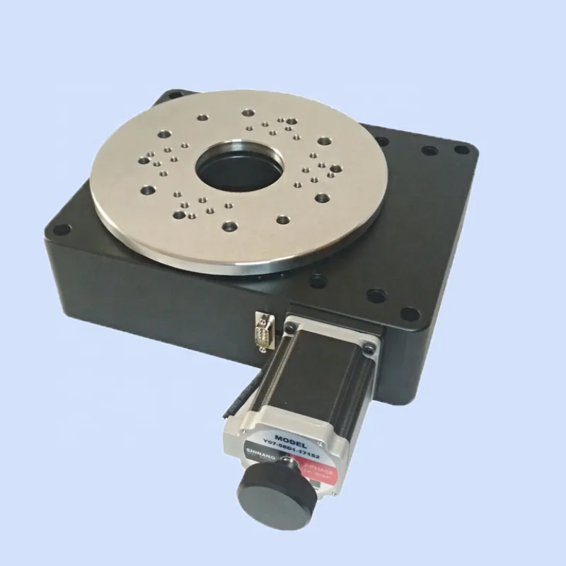
stepper motor rotary table quotation
Motorized worm gear driven rotary tables provide high angular resolution (the worm gear ratio directly multiplies the motor output torque and motor angle resolution) and holding torque. PI offers precision motorized worm gear rotary tables with both stepper motors and closed-loop servo motors with encoder feedback. While open-loop stepper motors are often used for their lower cost and ease of control, closed loop servo motors with encoder feedback provide higher speed, higher accuracy, and repeatability. PI also provides closed-loop stepper motor rotary stages, combining the best of both worlds. PI stepper motor rotation stages are provided with stepper motor controllers featuring a micro stepping mode for higher performance. For single axis applications, a compact and very cost effective single axis stepper motor controller is available.
For the best performance and highest velocity, direct-drive rotary stages with torque motors are recommended (link to new Rotary Stage Page with Direct Drive Torque Motors).
Control digital devices and make machinery more precise with a stepper motor from Alibaba.com"s wholesale equipment store. Our catalogue is the place to come when you need a replacement stepper motor rotary table or any other motor related products. You"ll find a huge array of wholesale motors, including step motors with high torque ratings that can offer incredibly precise control. Whether you"re constructing an astronomical telescope or a digital network for broadcasting, these motors will do the job.
Stepper motors are used in situations where devices need to be calibrated to extremely high levels of precision. They aren"t always the most powerful motors, but they do have very high torque levels, and this allows them to control devices in ways that other motors cannot. And they also tend to work well with digital devices due to their "step" mechanism. For instance, you can find step motors in many hard drives, handling millions of operations every minute. They have also become a go-to motor style for robotics installations. So you might need one for an advanced production line. When you need a stepper motor rotary table, finding the right motor is easy. Just search Alibaba.com"s catalogue and you"ll easily find what"s required.
Our stepper motor collection covers every base. Browse motors for use with mini computers like the Raspberry Pi or models designed for use with Arduino components. Look for permanent magnet motors, variable reluctance steppers, or hybrid syncronous steppers, and models with micro step, half step, and full step modes. Our listings include everything you need to control the most complex systems. So find a stepper motor rotary table and order what you need today. Everything can be handled with a couple of clicks, putting specialist stepper motor components within easy reach.
A Rotary Stage is a mechanical component of a motion system used to rotate an object in a single axis or plane of rotation. The terms rotary stage or rotary table are often used interchangeably with rotary stage. All rotary stages consist of a platform and a base, joined by some form of bearing or guide in such a way that the platform is restricted to rotation about a single axis or plane with respect to the base. In common usage, the term rotary stage may or may not also include the mechanism by which the angular position of the platform is controlled relative to the base.
ServoBelt Rotary Stages from Bell Everman are compact, high-torque rotary stages that offer through hole size and speed comparable to direct-drive rotary tables costing thousands more.
Room in the Middle. ServoBelt Rotary stages offer two different through hole configurations. Available with 50-, 100- or 200-mm center openings, our large through hole stages accommodate large bundles of power, signal and pnuematic conductors. They also make it easy to integrate laser and optical systems. Standard-sized models with 16- or 25-mm through holes offer a more economical choice when fewer utilities need to pass through the center of the stage.
Direct Drive Performance. Designed for NEMA 23 and 34 motors, the ServoBelt rotary stages offer speeds up to 1,000 rpm, continuous torque to 6.6 N-m and resolution down to 0.16 arc-sec with Renishaw ring encoders or tape scales for partial rotation.
Robust, Lubed-for-Life Bearings. ServoBelt Rotary stages incorporate large full duplex, angular contact bearings, imparting moment and load capacities far in excess of its usual application requirements. This excess load capacity translates into virtually limitless bearing life.
Cost Effective. ServoBelt Rotary stages offer an economical solution for a variety of medium-duty rotary motion jobs such as driving carousel tables on packaging and assembly machines and providing fourth-axis rotary motion for laser cutting and mini CNC machines.
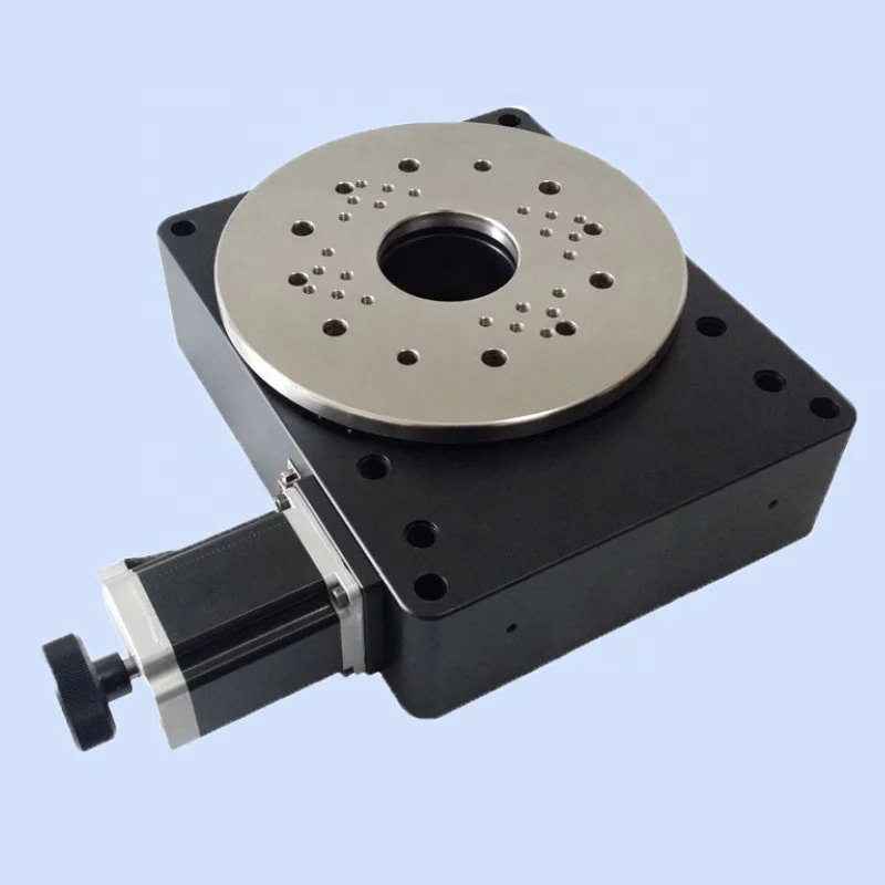
The 300 Series tables feature a rigid pair of quality angular contact bearings which produce smooth table top rotation. The low backlash precision worm gear drive provides exceptional accuracy and repeatability. All aluminum components have a black anodized finish and each table can have either a NEMA 23 or 34 motor mount attached. Threaded steel inserts in the table top provide for easy mounting of the user load while the 0.75 inch (19 mm) through hole provides easy access from below.
The 400 Series tables feature a rigid pair of 4 point contact radial ball bearings which produce smooth table top rotation. The low backlash precision bronze and steel worm gear drive provide years of high accuracy and superb repeatability. This rugged construction offers load capacities of 1000 pounds (453 kgf) and moment loads of 225 ft-lbs (305 N-m). The NEMA 34 motor mount and bushing can be positioned radially 360 degrees for convenient motor location. The large 4.5 inch (114 mm) through hole provides easy access from below.
Optional: Cover plates, gearheads, EOT & Home switches, linear & rotary encoders, power-off electric brakes, motor wrap packages and versatile mounting brackets for multiple axis applications
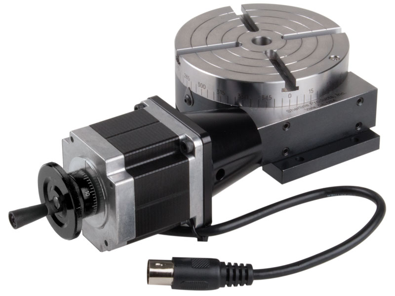
We designed this tilting angle table with a stepper motor as a way to offer a cheaper and quicker rotary axis for laser engraving instead of using our CNC rotary table. We have drilled and tapped the table top plate to accept one of our NEMA 23 stepper motors. You can mount any NEMA 23 frame stepper motor or servo motor to the table.* In addition to the stepper motor, we designed a chuck adapter for our 3- and 4-jaw self-centering chucks. This combination offers you a way to hold and rotate your parts.
Sherline’s CNC driver box comes equipped with an A-axis output cable ready to drive a 4th rotary axis. This rotary table is all you need to turn your Sherline CNC mill into a 4-axis machine. Just plug the A-axis cable from the external driver box or the built-in driver box in your Sherline computer into the matching plug on the stepper motor. The EMC2 software is already set up to handle G-code for the A-axis, and numbers entered after the letter “A” in your code are interpreted in degrees.
The same end result can be obtained by ordering a CNC ready rotary table and a stepper motor and attaching the motor, but this single part number does the same thing, making it easier to order and saving you the trouble of installing the motor on the rotary table.
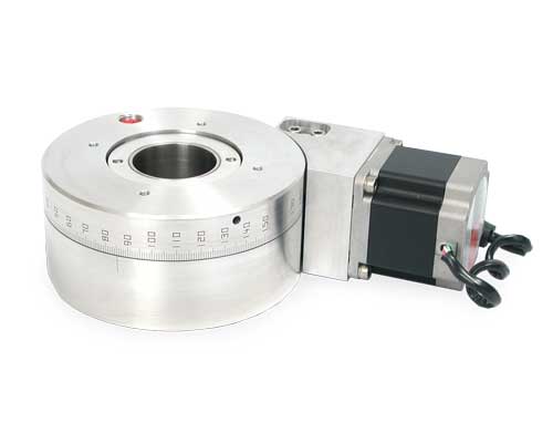
The resolution of 0.002 degrees is achieved with a 10 micro-steps per step stepper motor driver. This rotation stage is also available with a servo motor
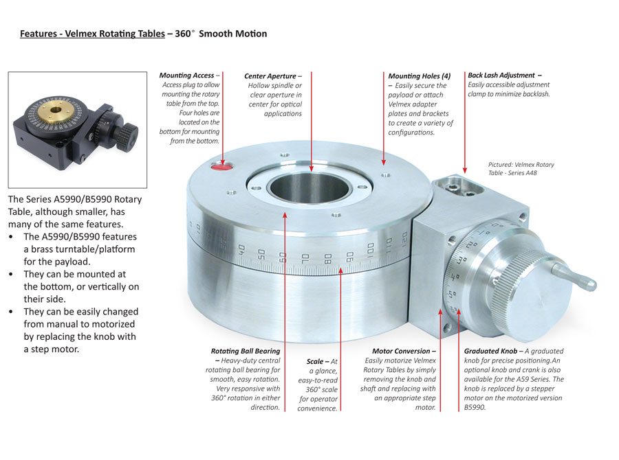
Normally, the worm/worm gear drive of Velmex rotary tables do not need any servicing. However, under severe conditions replenishing the lubricant will prolong the life of the gears. A small amount of Lubriplate can be placed in the access hole. See the user guide that came with your Rotary Table for instructions.
Yes, both models of Rotary Tables have a hollow spindle or open aperture in the center for optical applications. The manually-operated Velmex Turntable does not.
Yes, Rotary Tables can be and are frequently combined with other slides to achieve a particular motion or positioning. Which stage used in conjunction with the Rotary Table will determine which adapter plate or bracket might be required.
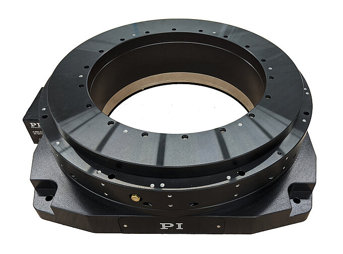
Our direct drive rotary tables provide high torque and are easy to integrate. They contain high-energy magnets in a simplified mechanical design and drive loads directly without the need for a transmission mechanism or gearbox. It allows customers to build them right into a drive system for flexible placement and integration with cooling pipes and cables, for example.
We supply a wide range of frameless motors, and our adjustable motors include an optical encoder, scale, bearing and housing. Given our selection, it can be challenging to choose the best direct drive motor for your project. Our engineers prefer to help you find the right rotary table for your requirements.
Our most popular rotary motor, the AXD series is characterized by a slim, compact "pancake" design with high peak and continuous torque despite the motor"s quite small form factor.Direct drive and brushless motor
The ACD series is a set of ironless rotary tables. This motor is cogging-free and features high-resolution optical encoder feedback and low speed variability. This permanent magnet motor is equally suited for either low or high speed applications.Zero cogging coreless motor
The ACW series features a cogless construction and lean design, with high-precision coding and ultra-precision bearings. Together, this results in our highest performing motor in terms of repeatability and smooth motion.Direct drive brushless motor
The ADR-A series is available with both low and high speed windings and is fully equipped with an encoder and bearing. This series has a high slot fill factor and generates very high torque.Direct drive brushless permanent magnet motor
The ADR-B range performs at a similar slot fill factor and torque density to the ADR-A range, but has a larger center hole compared to its equivalent.Direct drive brushless permanent magnet motor
Similar to the ACD series, the AXM series also features an ironless design and zero noise characteristics. This motor has a compact design, making it ideal for applications with specialized size requirements.Direct drive brushless permanent magnet motor

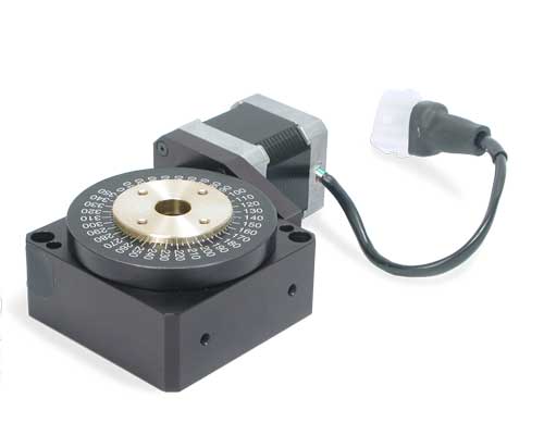
The Dover RTR™ series stages are available in 4-, 6-, 8-, 10-, and 12-inch diameter rotary stage versions that include a preloaded, anti-backlash drive assembly to provide exceptional angular accuracy and repeatability. There is a standard internally mounted Hall effect reference sensor that is wired directly to a screw locking connector for homing position registration accurate to a single step. A stepper motor with a manual knob and a flexible coupling are included with this motorized rotary stage. A second sensor can also be installed to electrically restrict rotary table travel in applications where the full rotational travel needs to be limited to a specific angle of travel less than 360 degrees.
Clear apertures (or through hole) are optionally available in different diameters. Our integral rotary motor encoder can be specified with our RTR™ series rotary stage, where it provides 0.001-degree resolution encoder feedback when combined with a 180:1 worm gear ratio, 200 step-per-revolution stepper motor, and a divide-by-ten micro-step drive. For increased rotary motion resolution, 400-count stepper motor or rotary servo motor are available.

I recently read an article in Model Engineers Workshop Magazine (December 2016 issue 249) for adding a stepper motor drive to a rotary table. I don′t use my small Vertex rotary table very often but I thought this might be a useful project to learn a little about stepper motors and digital control of machinery. The article by Carl Wilson describes how to use an Arduino micro-controller to control the rotary division process. Much of the coding is contained in another article in Digital Machinist by Gary Liming. So no original thinking by me here, just a rehash of other engineers good work. All the links and useful information can be found in the Glossary at the end.
Prepping the table can be as simple as doing nothing, a complete strip down and re-build with thrust washers and the like or somewhere in between. There are a few articles on the web giving details (see glossary). Software setup and programming the Arduino is the quickest part and if you use Gary Liming′s software without alteration, the programming takes just a few seconds. Assembling the electronics is mainly about fitting the bits into the box and requires a bit of inginuity to fix things in place. The boards are fairly flimsy and things, like the display, tend not to be square or flat, I found.
The stepper motor mounting I made from three parts and assembled with Loctite and screws. I have no doubt there are other ways of making this or a suitable motor mount could be found ready made and adapted to fit the table. You will probably want to test things as you you go along rather than leave everything to the end. I discovered I had a faulty motor driver, easier to deal with whilst still uncased. I don′t think it makes makes any difference which order things are done.
This is covered elsewhere on the web in some detail so I have just made a few notes that may be of interest. Dismantling the table is quite straightforward, just look for allen headed grub screws at the bottom of deep holes. The notes refer to my 4" Vertex table.
Start off by removing the handle, the table locking clamps and the worm engagement lock. The handle is just one screw but watch out for the shaft key which is small and easily lost. Photo (2) shows the board I made to store the table with a cutout for the handle. The stepper motor will also need a similar storage solution. I used pliers and some cardboard to protect the finish to unscrew the table clamp handles. Remove the engagement lever and collar, two grub screws and it slides off, this is the part that the motor connector will attach to, it has three ready tapped holes for when used with division plates.
Remove the cam shaft securing and adjusting collar (4), four cap screws. Remove the grub screw that sets the worm engagement depth, found at the bottom of a deep hole (5). The worm shaft and cam bearing can now be removed as one unit, rotate the table and it will push the spindle out.
Turn the table upside down and remove the table bearing and adjustment plate (6), four cap screws. The table can now be removed, mine was pretty clean (7) not having been used much, there wasn′t even that much grease. Now that everything is apart it can all be cleaned re-greased and re-assembled. The worm drive shaft can be slid out of the cam adjuster by removing the collar, it is a ground shaft with an oilway and a very good fit in the cam adjuster.
Other than adjustment to remove backlash I didn′t make any changes to my rotary table, it was in fact pretty good before I started. If you have an older well used table it may take a bit more cleaning to remove old grease and any swarf that may have found it′s way inside.
Other parts worth note are the cam shaft retainer / bearing (4) and the table retainer / bearing (6). These both feature four cap screws which bolt the item in place and four grub screws which act as jack-screws to prevent clamping the rotating part. When reassembling it is worth adjusting these carefully to limit the table lifting whilst still turning freely and likewise to prevent the cam shaft moving in and out. I noticed with the table bearing / retainer that there was a noticeable stiff spot so it is worth rotating the table through a full 360° whilst adjusting. The cam shaft could be locked in place if you think there is no need to disengage the worm gear. Last bit is to set the worm engagement, this is controlled by a grub screw at the side (5) which engages with a slot in the cam shaft to prevent rotation. If you undo the grub screw and fully engage the worm it will be very difficult to turn, tighten the grub screw just enough so that the worm turns easily with a minimum of backlash.
This is like assembling a 3D jigsaw without a picture, I just made a couple of dry runs to see how all the bits will fit into the box! The largest single part is the power supply and if this is going into the box it will pretty well determine where all the other parts fit (you could use an external 12V supply making the control box much smaller). An external power supply could avoid overheating problems but if you put everything in the one box try to leave some airspace around the power supply and stepper driver board.
The parts are shown (12) above and are the Arduino Uno, the LCD shield, the cable gland, TB6560 stepper driver, switches, plug, socket and power supply. The circuit boards are all pretty flimsy and the mounting holes are very close to the edges. The LCD shield has a seperate smaller board for the LCD soldered on top and the two boards were not particularly parallel. There is also a multi-turn variable resistor on the board which cunningly sticks up higher than the LCD face. If you are adept with a soldering iron it can be re-positioned on the other side of the PCB. I solved the non-flush pot problem by using a 1.5mm clear polycarbonate sheet between the box lid and LCD with a small cutout for the variable resistor.
I fitted as much as I could to the box lid, only the mains in and stepper out are fitted to the box. The display needs a cutout in the lid as do the three switches and a number of 3mm holes for various mounting screws. Once I had worked out the position of all the bits I marked the inside of the box lid for the position of the LCD and switch cutouts. I set this up on the mill and used a 5mm slot drill to remove the cutouts, the ABS machines very easily. I fixed the lid to an off-cut of MDF with woodscrews through the mounting holes, I also used double sided tape to make sure nothing moved. A couple of T-nuts and studs fixed the MDF to the mill table (13). With hindsight the double sided tape was overkill, it took me longer to get it off the lid than it did to do the machining. The corners of the switch cutouts I filed square, I drilled the various mounting bolt holes by hand as I did for the other round holes opening them up as necessary with a taper reamer and file.
I used nylon nuts and bolts to fix most of the parts, mainly because I had a pack of 100 and I didn′t have many M3 screws handy. The LCD shield and Uno can be bolted straight to the case front as can the power supply. The motor driver board needs some standoffs to clear the Uno and I made these from ⌀6mm aluminium rod. I also used a short length of ⌀3mm rod inside a plastic tube to support one corner from a spare hole in the Uno board. Once all the PCB′s are in place it just remains to connect the wiring.
I have included a drawing that shows how I made the mount, you may need to adjust dimensions to suit the components you have. I used 6082 T6 aluminium ¼" (6.35mm) plate to make the two ends of the connector and a length of 2" x ¼" (50.8MM x 6.35mm) thick wall tube for the middle bit. It is often still easier to get material in imperial sizes, come to that the stepper motor is imperial size as well.
I made the two flat plates and then fitted the motor, flexible coupling and rotary table together to measure the shortest length of tube that would work. The dimensions for the motor mounting plate were copied from the motor spec sheet.
The motor plate is from a length of 3" x ¼" bar, cut to length and then mount flat on parallels in the milling machine vice. Clean up one cut end then reverse and mill to length. Turn 90° clean up the edge reverse and mill to length. With the part still in the vice use an edge finder in X and Y directions to position first hole for drilling use co-ordinate drilling to position the remaining 3 holes (19) and a centre hole (much easier with a DRO, I still count turns). The centre hole will be the motor register. Drill and bore this out to 38.1mm (20) I found the easiest way to check the diameter was using a short length of 1.5" (38.1mm) bar. Strange all the dimensions for the stepper motor are given in mm but they are definitely made with imperial measurements, oh well provided everything fits together!
That was the first time I had used the boring head in the mill and I tried to use it to cut the recess for the tube. This didn′t work too well as you can′t really get a flat bottom to the recess. I remounted the plate in the four-jaw chuck on the lathe (21) with the motor register running true and completed the recess, 3mm deep and to suit the tube diameter, with a boring bar.
I used another bit of 3" x ¼" bar to turn the plate that bolts to the rotary table. I drilled a 10mm hole in the centre of the plate and used a length of studding to hold it (22). The studding has two nuts locked to it which fit against the back of the chuck jaws and a nut and washer clamp the plate against the front of the jaws, there is a centre in the outboard end of the studding for support. I used a trepanning tool to remove the corners and then turned the O.D. to to size.
When the R.T. mounting plate is the correct diameter add a step 3mm deep with 38.1mm diameter to create a short spigot to fit the tube bore. Remove from the mandrel (studding) and mount holding the just turned spigot (23), bore out the centre hole to 21mm to fit the R.T. collar. To finish this part it need the three mounting holes drilled to match the table. I clamped the table index ring to the plate, they should be the same diameter, then spotted through with a drill that just cleared the threads in the index ring. Unclamp and drill the holes 5mm, there is no other alignment so keep the holes small, don"t use an M5 clearance drill.
The last part to make is the tube that spaces the two plates apart. Cut to just over length and face one end, reverse and face to length. I made my tube 53mm long but you may need to adjust this to accomodate the motor spindle length, the flexible coupling length and the R.T. dimensions. Hit a slight problem here as I used thick wall tube so that I could add some screws to fix the plates on rather than just rely on adhesive. If you are happy just using adhesive a thinner walled tube would work. I found that the bolt heads interfered with the tube (or vice versa) so I had to cut three pockets (24) to clear the heads and allow assembly.
The three parts are "glued" together, I used Loctite 603 which is a high strength oil tolerant retainer. Check alignment before joining, it will depend on the orientation of the holes in the index collar on the R.T. probably easier to join the tube to the table end first and then bolt it in place. The motor mount can then be aligned so that it is square when in use. I had an interesting experience when I first tried assembly. applied the Loctite placed suitable weight on top and left overnight. The following day removed the weight picked it up and it came apart. Apparently Loctite "goes off" still mine was a few years old! If you want to add screws it is probably easier to do this after assembly, I used 3 M3 C/S screws in each end, a bit belt and braces as either screws or adhesive alone will probably do the job.
Not much to this really, first bolt the connector to the rotary table. Slide in the flexible coupling and tighten onto the table drive, I aligned it so that the grub screw would tighten into the keyway. Fit the motor using four M5 capscews, nuts and shakeproof washers. Tighten the coupling onto the motor shaft and thats the mechanical bit done.
If you have not already done so check and set the switches on the TB6560, I set the current limit to 2A, turn off micro-stepping, set standby current to 50% (the switch positions are printed on the board). Plug the motor lead into the control box DON′T UNPLUG THE MOTOR WHEN POWERED UP! you may well fry the electronics.
To test I went through each menu item in turn and made sure it did what it was supposed to. I discovered that clockwise and anti-clockwise were reversed but this can be adjusted in the software. I also discovered that I had wired one switch back to front and needed to reverse the leads fortunately just swapping a couple of push on connectors. Found that the motor vibrated rather heavily, haven′t got to the cause of that yet. I also set the table to zero on it′s scale and checked that the angle turned matched what the display said for a full 360° - it did.
With a bit of work on the software, to slow the motor down, I don′t see why the table could not be operated under power, to mill say a semi-circular slot. WIll also need a bit of work on the switch de-bounce software for this to ensure reliability, as it is it is easy to double press keys. Nice little project a good introduction to both the Arduino and to stepper motors neither of which I had used before.
As I had to take everything apart I added a reset button (29) by soldering leads to the back of the shield button in the same way as for the other buttons. Caused me some aggravation as the first button I found in my "bits that will be useful one day box" remained steadfastly open-circuit when pressed, still it was probably 30 years old! Last but not least a short video (30) which shows the table spinning quietly in run mode and then vibrating in step and angle mode. It makes me think this might be software generated as that is the only difference between the modes.
Gary Liming′s Website- describes the making of the original step-indexer which could be used in place of a rotary table and outlines the software in a bit more detail.
Model Engine Maker Forum- thread covering the preparation of a Vertex rotary table ready for automation. This was done by John "Bogstandard" Moore in readiness for the Division Master system but the mechanics are the same.
Stepper Motor Data- This is the specification sheet and wiring diagram for a similar motor to the one I used which is no longer available (2020). Any Nema 23 size motor around the 2Nm holding torque should be quite sufficient indeed a smaller motor may suffice if you have one to hand. My original motor was 8-wire but a 4-wire motor is just as good and will avoid some soldering.
The list above is for the major parts required for the project. The suppliers are those I used and the prices were correct in January 2017. (Please note the links to some of these items seem to change weekly, apologies if they don′t work) I make no particular recommendation as to the suppliers it is just where I found the bits needed, it is likely that better/cheaper/different parts are available from myriad locations on the web. In addition to the bits listed you will need - hook-up wire, solder, nuts, bolts, spacers, cable ties, crimp connectors and sleeving. Please note that the above table doesn"t display well on a small screen, try rotating to landscape to view!
Many of the links in the Glossary and particularly the Parts List table have gone missing over time so I have tried to update them with currently available parts and information. In fact none of the parts are particularly critical and a bit of web searching will find suitable replacements. The Model Engineer Forum link is still active and one of the later additions is the replacement of the switches with a cheaply available numeric keypad. I haven"t carried out this mod but it looks quite interesting.
I have also been told that the TB6560 has an inherent quirk, I quote "It may be of interest to you to know these modules apply power to the IC in the wrong order. The manufacturers specification clearly states the 5v logic voltage should be applied and allowed to settle before the higher stepper motor voltage is applied. On these modules the 5v is derived from the (say) 24v supply which compromises the “power-up” sequence and has resulted in “blown” chips." It may therefore be prudent to avoid this and use the TB6600 driver module.


 8613371530291