
hacker rotary table free sample
Thisbookletcontainsanoverviewtothevaryingdesigns ofrotarytableunitsavailabletoday. ____________________ Anunbiasedandgeneraldescriptionofthe drivingmechanismsandtheirbenefitsandfailurestoindividualapplications
INTRODUCTION We are pleased to provide a break down of a number of drive systems currently available within the market place in the design, manufacture and use of rotary table devices. There are several different systems available as can be seen below, all of which have benefits in different types of use with corresponding deficits and limitations in use. We have attempted to highlight as many as possible in this short manual to assist with the making of the correct purchasing decision for you. This document is prepared to assist in the selection of the correct type of rotary or rotary tilting device for various types of usage. 1) 2) 3) 4) Conventional Worm & Wheel device Spiroid gear system Ballscrew driven rotary table Direct Drive rotary tables
This document is written with the knowledge and experience of the supply, sale and service of devices with all these integral operational styles and within a large array of industries and component sizes and types from 1kg to 100,000kg and 70mm to 5,000mm in diameter covering more than a 40 year period. It is also written with as little bias as possible to any manufacturer or style or type of device so that the reader can make their own informed judgement. There is a wide range of products available within the market place from a large and varying number of manufacturers. Generally all the manufacturers have what can be described as a reasonable product and range, some of whom have used their experiences and customer feedback to develop the product further on an ongoing basis. We are not looking here to promote and denigrate any one or more individual manufacturer, just to highlight the differing techniques used within the products to maximise certain areas of performance. We have chosen also to detail the down side to each type of design from our own knowledge and experience, again this is not pointed in favour of, or against any manufacturer. Should you wish to discuss your application with the writer there is an email address at the end of this section, advice is free and without any obligation whatsoever. sales@cncrotary.com
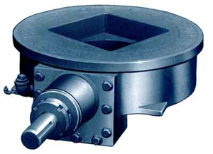
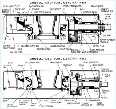
CONVENTIONAL WORM & WHEEL SYSTEMS The CNC rotary table and subsequently the CNC rotary tilting table were developed around the original manual table technology using the standard layout of a worm and wheel. The worm and wheel hardening process was increased to take account of the potential added wear characteristics from the higher speed and acceleration and deceleration associated with the higher speeds and the automated process. The hardness levels were calculated through major testing programmes and the standard hardness range of the general worm and wheels used in the Worldwide manufacture is between 45 and 60 Rockwell dependent on the manufacturer. Most manufacturers offer this type of device, some claiming special materials, however the benefits claimed are not as extensive in practice. The Japanese manufacturers generally have tables with harder worms and wheels than European or American manufacturers and these seem to be more robust under heavier use. The standard worm and wheel process is considered to be the common solution to the drive requirements on most rotary tables currently in manufacture today, simply due to historic design and the general success of the format. The standard worm and wheel system provides a good level of accuracy for the positioning of the device and general accuracies on smaller tables from say 100mm to 500mm id around +/- 20 seconds of arc and most manufacturers quote this sort of accuracy, one or two in special devices may be slightly worse than this. When we move to the tilting axis however the accuracy generally deteriorates considerably to as much as 3 times or more than the accuracy of the rotary axis, this is due to the additional loading on the gear system when driven against a load and when the mechanics are stressing the gear set, when lowering in a tilt move. To improve accuracy direct axis measurement is used as an option, this can provide its own problems with these devices due to the mechanical wear characteristics of the gear type. EXAMPLE - NIKKEN WORM When the gears wear or are damaged the position window required by the encoder can not always be maintained under the mechanical loads and the combination of the motor attempting to keep the mechanics within the position window has the effect of shutting the machine down with an axis
position error. It is therefore an ongoing maintenance issue to keep these devices with this electrical configuration running during production type set ups. The tilt or swivel axis point can make a considerable difference to the actual achieved accuracy. Some products tilt on centre line, other hinge and some are just off centre. Tilting off centre can increase the errors if measured from the tilting point as angular errors are physically greater the further from the axis point and the strain on the gear set increased. In operation the worm and wheel provides good service over a long period of time, the main problems come with collision damage because only a small amount of gear is in contact with the worm at any one time and therefore damage is local to the area of the wheel in contact at the time of the collision. The softer the wheel, the greater the amount of potential damage, the harder the wheel or shaft there is a potential for the shaft to break or teeth to shear from the worm wheel. Both these phenomena are a known and accepted problem. Many customers have had to take the steps of using good areas of the wheel until these areas are no longer usable, particularly a problem with tilting axes where the wheels are used and rotated 180 degrees and used again. These problems are experienced in uses where the same components are produced on an ongoing basis and less problematical for general subcontract uses. When the tables exceed around 500mm diameter, particularly in the case of the European manufacturers, the accuracies quoted for the worm and wheel set tend to improve as the gear sets are larger which make the surface contact greater and maintaining the higher quoted accuracy becomes possible. This accuracy is maintained over a much longer period of time due to the physical size and strength of the mechanical gearing. The accuracy will improve generally to +/- 15 seconds, however on the larger diameters it is normal to expect that direct axis measurement will be used for position, as angular errors, even small ones can become quite sizeable at 500 or 1000mm radii for example.
The Spiral worm gear was developed for use in rotary devices to improve the wear characteristics already discovered in the conventional worm and wheel system The spiroid gear is based on the rear axle of a car (the Hypoid gear) where the gear shaft runs across the face of the spiral formed wheel thereby providing up to 6 times more gear contact than the conventional system. Due to the gear contact a higher moving torque is required to position the table and this should be considered when selecting suitable servo motors.
Two further problems were that this additional manufacturing process added cost to the device and that there was a patent on the gear system meaning limited sources of manufacture. In special cases where a large bore table was required, the spiroid gear system has an additional problem, as the gear going across the face means there is limited room to open the centre bore. The hardness of gear set was sufficient at 55 Rockwell to ensure the wear characteristics were good and long life can be expected without any signs of backlash or damage manifesting themselves on tables up to 400mm or thereabouts. On tables larger than that of around 1000mm or so where a table is used continually, there are some issues with the generation of heat from the gear set due to the amount of metal contact with the toothed gear. Long term accuracy and repeatability of this system is good, direct axis measurement is recommended on tables over 400mm diameter and all tilting devices over 250mm. Manufacturers of tables with this type of gear are SPIRSIN (tables to 1500mm) and ZEATZ (tables to 300mm).
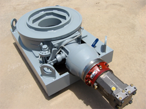
RECIRCULATING BALLSCREW DRIVEN TABLES The recirculating ball drive rotary table was originally designed to resolve accuracy issues with rotary transfer machines, where accuracy and repeatability were vital in part production and the indexing device was used to position at the same point over and over again The problem comes with localised wear as already mentioned within an earlier section, where repeatability becomes more of a problem for customers requiring large batch manufacture, or repeatability on a range of component parts. A large number of machine tool axes are driven using ballscrew method and it is known that this method of positioning is fast, rigid and highly accurate, in addition it will function for a long period of time without the need for maintenance or attention. It is therefore only logical to use this process in a rotary application and format to achieve similar performance within rotary devices.
The age old problem of damage to worm and wheel system is minimised as the ballscrew assembly has at least 85% of the balls in contact with the spindle at any time which allows the shock to be dissipated throughout the device therefore minimising any actual damage. This system is ideal for replacement to a direct axis measurement project as the inherent accuracy is some 4x better than a conventional rotary axis worm and wheel system, thereby negating the need for expensive encoders and the problematical description earlier of the tussle between the mechanical and measuring elements. The system requires a higher input torque to drive the table because of the 85% contact but the mechanical ball system can work as a brake in most cases also negating the need for pneumatic or hydraulic supplies together with the associated valves and their failings. The system is manufactured in a modular block build system which allows the motor positions to be as varied as required by the installation as a whole, so there are no real issues with guarding, cable routing or other out of the box issues. The down side to this flexibility is that they are not off the shelf items and are manufactured to order, taking several months. They are also not a device to be used for heavy slab milling as this is not putting the additional cost of the system to its best use. This device is a patented system manufactured exclusively by Detlev Hofmann in Germany. The modular block size range 80mm to 320mm and due to the ball drive this system allows the largest of all centre bore sizes compared to the overall frame size. It is therefore easy to fit any special chucking arrangements such as Pallet systems 3R or Erowa for example.
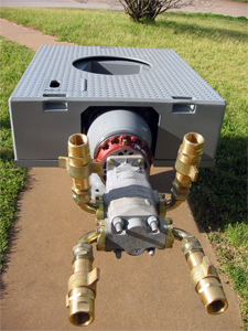
DIRECT DRIVE ROTARY TABLES The newest technology to find its way into the rotary table arena is the Direct Drive rotary table system. These devices are being introduced by many of the existing rotary table manufacturers and this does away completely with the mechanical gearing, no worms and wheels, spiral gears or ballscrew transmission here. Drive for the table comes directly from the electromagnetic force of the motor. In these designs the motors mount directly over the spindle, this has the major benefit of removing the age old issue of motor positions on CNC tables, which particularly with the old DC servo motors and the relevant length of these, caused issues with the ever reducing space within the target machine guarding.
You will see from the picture how compact this type of device is, they can be constructed not only as rotary devices but also in rotary and tilting format In the tilting arrangement care has to be taken to the centre height of the device as it needs to be higher than a conventional system to allow clearance of the motor below the table when moving through the horizontal position (vertical axis). These devices allow high speed acceleration and positioning, however for the positional accuracy a separate encoder is required, this may inhibit the working bore (centre hole) of the table subject to the encoder selected. These devices have no mechanical wear other than the bearings and the seals, the down side to the device is that the integration to the machine is a little more complex and if motor problems are experienced it is not quite as easy to obtain the motor and fit it as a conventionally driven device. The cost of the motor is a major additional factor however there are no worm and wheel costs, so this is the major off set to the original product cost. These products are a little new to be fully tested and problems that are not yet being experienced may come to the fore. To date however we can provide only good feedback from clients.
CNCROTARY.COMUnits 33 & 34, Circular Road Storforth Lane Trading Estate Chesterfield S41 0QLTel: 0870 061 9000 Fax: 0870 061 9001 e-mail: sales@cncrotary.com web: www.cncrotary.com
I am starting out with my recently acquired mill, and the (ever longer) list of projects contain several that would be easier (possible!) with a small rotary table.
The Mill (an SX1LP) seems to suit a 4" table. Reading the forum about such devices I think a simple H/V one would be fine. There seem to be two main choices (in my price bracket) 36:1 (10°/turn) ratio and 90:1 (4°/turn) ratio. The former are a bit cheaper, but the handwheel is on top in the vertical position while the 90:1 seem to have the handwheel horizontal in both orientations which would seem more useable on my small mill.
A 36:1 table turns more quickly than 90:1, making it faster to use, but less accurate. Reduced accuracy doesn"t matter provided only simple angles will be needed. Stuff like hexagon heads.
However, new rotary table owners are soon likely to find jobs where extra accuracy is valuable! Gear cutting is the obvious example, but there are many others, such as cams, helices, drilling awkwardly spaced PCDs etc.
If gear cutting & chums are ever on the menu, a 90:1 table is better. But, oh dear, more money - gear cutting requires a set of division plates or a stepper motor with driver. Manually moving a table to cut 57 teeth ( 6.316° ) per step, soon reduces operators to a nervous wreck and mechanical help keeping track is pretty much essential. I"m not sure 4" tables can be had with division plates, and would recommend a 5" 90:1 table with plates if any advanced functions are on the cards.
Strong rotary tables cost big money. I suggest the hobby type and some expensive makes are unsuited to heavy work whatever the ratio. Brutally hacking out the inner arcs and spokes of several big traction engine wheels at top speed will trash them. Treated with mild respect for ordinary work either ratio should be fine.
I"m actually quite liking using 72:1 and tend to pick that up in preference to my 90:1 table but not sure if there are any to fit your budget with that number of turns as the ARC ones are a bit more costly than the norm.
If (and I repeat, if) you go down the route of adding dividing plates to it, you will almost surely have to calculate all the plate and hole numbers for the 36:1 ratio table.
As far as I can tell, you"re on your own if you want to have a division plate set-up. I was part way through designing such a thing for mine when the need for a 63 tooth changewheel became urgent, so I went for the cheap and cheerful approach of printing a strip of paper with the appropriate divisions marked on it, and taping it round the circumference of the table. Eyeballing alignment with the index mark on the table worked fine - it may not be super precision, but my Imperial threads screw into existing fittings without a problem (and the 63-tooth method isn"t perfect anyway).
The only slight irritation with this method is that the strip is 319.9 mm long for my table, so you have to print it at 33 degrees to fit it on a sheet of A4 - it would have been nice to have printed a whole lot of them on one sheet for different tooth numbers.
The 36:1 model would probably have bigger, stronger teeth and more suited for machining while rotating the table while the 90:1 model will be more accurate but will have smaller, weaker teeth. No problem if locked in stationary position but not as good while rotating.
A more important question may be the number of slots. I think 4 slots is much more useful than 3, which many of the cheaper tables have, as it is easier to fit a 4 jaw chuck which will allow more accurate centering and take up less vertical space than a 3 jaw. Also generally allows easier clamping.
Peter, I have the SX2P mill and apart from it having 25mm more height between table and spindle the table size and X and Y travel are the same as your SX1LP. I started out with a 4 inch rotary table (a cheapie dont go there) but I found it a bit too small. A 6 inch would be too big but came across a 5 inch which is what I went for, came as a set with chuck, tailstock and plates.
A picture below showing its size against the table which gives you some idea. With the 4 jaw chuck and backplate fitted and a Jacobs in the spindle there is only 45mm between the two chucks so I have had to resort to shortening one or two drills in the past. There is more space of course with collet mounted drills and cutters and without the 4 jaw there is 205mm between the rotary face and spindle.
Thanks for all the advice - very helpful. The main projects I have on the (ever growing) list that need some sort of controlled rotation are a motor mount for the Taig lathe so that I can fit a DC speed controlled motor, and some calibrated dials (HH"s Lining tool is on the timeline for that and the ratchet wheels will need the table). The motor mount needs curved adjustment slots but it will be in aluminium so less of a risk.
Thanks Paul for the warning. The reason I asked about relative strength was that the cheap 36:1 tables all seem to have the handle angles towards the centre while the 90:1 ones it is straight. That suggested the cheap tables had a smaller wormwheel, and I was wondering.
Just an update for anyone interested - against advice I ordered table & index plates from a remote supplier (China!) but who shipped from the Czech Republic so no customs or duty (until 1st Jan). Table arrived by courier in less than a week. First impressions good. certainly looks more than adequate for my needs and mill.
On investigation it turned out to be a 110mm diameter 4 slot 72:1 table rather than the 90:1 I thought I was getting. So opened discussions with supplier. Very responsive - offered a swap, or a discount if I kept it. Based on Jason B"s comments about usability I decided on the latter.
I’ve got a couple of threads running where rotary tables have been mentioned (ok, mainly by me). One thing to put to bed straight away: I don’t really *need* one, but it would be handy for some jobs, and - primarily - good fun to play with.
Ive got an SX2P mill, and a 5” table was suggested as a good size for that. Soba was a brand mentioned, and one of the usuals has a set including table, tailstock, 4-jaw chuck and dividing plates. Cost is about £340 from Chronos, delivered. I understand that quality could be acceptable, but chances are it might need some fettling. I watched a review video, and it seemed as expected.
Is there a ‘rotary table 101’, for example what’s the correct way of centering the table under the spindle, and when using the 4-jaw chuck how do you subsequently centre the work in that?
Mine came with a 3 jaw and that gets used equally in both vertical and horizontal modes the 4-jaw SC would be similar. Also have a flange mount ER32 that gets used sometimes as it"s a bit shorter and also allows the spindle collet to get closer to small work when table is vertical.
To centre my rotary table I have a centered plug which fits into the rotary table centre. This allows put a centre into the mill spindle and just run it down to the rotary table to centre it to the spindle then bolt it to the mill table.
When I bought my (secondhand) rotary table I also bought a small import 3-jaw chuck. I"ve never fitted it and not missed it, so I never will fit it. I mount work direct on the table.
Andrew - the first part I’d use it for is the small (c.30 mm) diameter aluminium output shaft blank for my son’s rc car (as per earlier thread) The Chuck would seem the obvious choice to hold it, but the height restriction could be an issue. What would be the best way of centering and holding a piece like that direct to the table? Make a temporary base plate and screw the bar vertically to that, then clamp the plate to the rotary table? Or something like that?
To centre my rotary table I have a centered plug which fits into the rotary table centre. This allows put a centre into the mill spindle and just run it down to the rotary table to centre it to the spindle then bolt it to the mill table.
I was wondering if something like that is accurate enough. Sounds straightforward. I guess you could also turn and drill a tight fitting centre plug, then align the table so the drill presses straight into the hole?
For a more accurate set-up, mount a dial indicator on the mill spindle and use it to locate on the morse taper of the rotary table spindle. (or the machined recess on the end of some RT"s). Carefully turn the mill spindle by hand to achieve zero movement of the indicator. Bolt down the RT and check again to see if it has not moved.
That"s obviously an - ahem - suboptimal setup, but shows what can be done in the way of fitting quarts into pint pots. The work was ~1" diameter and the tool mounted in an ER25 collet chuck. I didn"t have problems with headroom - it was the size of the table which was problematic. Anyhow it worked:
Over the years I have built up a fair number of simple arbors which get reused or it"s not hard to knock up another and these just go into the chuck and the work screws to those. Not sure I would want to try clamping this 1/4" sq x 3/8" long part direct to the table and still be able to get at it will a 6mm cutter and not hit any clamps
As you don"t have any form of indexer like a 5C spin indexer you will end up using the R/T to cut square or hex shapes onto small parts which will again be quick and easy to hold in a chuck or collet fixed to the table
......the first part I’d use it for is the small (c.30 mm) diameter aluminium output shaft blank for my son’s rc car (as per earlier thread) The Chuck would seem the obvious choice to hold it, but the height restriction could be an issue. What would be the best way of centering and holding a piece like that direct to the table? Make a temporary base plate and screw the bar vertically to that, then clamp the plate to the rotary table? Or something like that?
I"d concede that a chuck might be the simplest solution, but not necessarily the most accurate. My rotary table has a 1" parallel hole in the centre, which is way more useful than a Morse taper. So I"d make a 1" spigot with a flange for clamping to the table and a recess to locate the work. There would also be a hole for a screw into the part to be machined.
If you could not get the chuck in then a 5mm pin held in your collet chuck and lowered into the central hole would locate the part and a couple of small clamps will hold it down by the flange. Zero DRO before raising head and changing to the cutter. Though as I said it could be done without a rotary table too.
My advice is not to get wrapped round the axle worrying about the quality of hobby tools. If the best possible rotary is really needed (and I suggest it"s not), then buy an industrial model. It will cost a few thousand pounds, and although it will be somewhat more robust, don"t expect it to be bullet proof. Many a well-made rotary table has been wrecked hacking out big wheels for model traction engines!
Most hobby rotary tables are of the HV6 design. A worm drives a cogged wheel and turns the table on a simple plain bearing. Though obviously made down to a price, they"re reasonably accurate and sufficiently sturdy for most amateur purposes. They"re aren"t high-technology, nowhere near as difficult to make as a computer hard disc.
Today the world is flooded with mid-range tools, affordable rather than excellent. Not intended to last forever, they are nonetheless generally acceptable for the light duty found in typical hobby workshops. Many products come from similar anonymous factories, and are rebranded by a local seller. But be aware that some versions are too cheap, or customer returns, or manufacturer rejects. The customer probably has no idea who made the item, or even which country or countries it came from. And for this class of kit, it rarely matters. The customer isn"t looking for "quality", he"s after "value for money" and "fit for purpose".
In this way, with the R T in a suitable position on the table, the Tailstock is clamped to the table, so that the Tailstock barrel can be inserted into the bored arbor.
The Tailstock barrel locates the R T.so that it can be clamped to the table. The Tailstock can then be repositioned wherever is suitable along that T slot, for the work in hand.
This is not present - it’s just a plain threaded collar, which in my table wasn’t true to the shaft. This makes preload and play impossible to get right, since if you remove the bind, you get clearance 180 degrees round. I tried to clean it up in the lathe, but with limited success. If the roller bearing was fitted as listed, it would be way better. Further to this, there’s a grub screw which is a limit stop for worm gear engagement with the main gear. This is just loose in its thread, and would be free to vibrate either way, changing the critical engagement adjustment preset. I substituted a cap head screw and locknut which can be seen in the image below (just above the silver engagement lever). Anyway, once adjusted to the best of my ability, I got about 3 minutes of backlash on the handwheel, and about 0.0035” play at the edge of the table:
The chuck is OK, very stiff, but no big deal. The supplied t-nuts clashed with the lock plates, and needed thinning on the linisher. Contrary to some reviews, my supplied chuck key is a perfect fit. I tried the table/chuck out by helping my son making some differential parts for his r/c car. This involved milling sectors from a small diameter shaft:
Pleased your generally happy with the Soba 5 inch table it should serve you well. I must have been lucky with mine I have 1.5 minutes backlash at the handwheel and 0.0015" at the table edge. In a full 360 degree rotation I have a couple of spots each about 15 degrees worth where it goes a tad light but hardly noticeable.
Don"t forget you can gain around 40mm in Z if you use finger collets against using the collet chuck. I have a 6mm and 10mm which take most of my regular cutters. I mainly use the collet chuck but if you have a tall job plus a table mounted vice or chuck it could make all the difference to fitting the job and tooling in. The 40MM extra on mine is based on my finger collets against the collet chuck both from ARC.
My Tailstock has tappings for a key or dowels. Because my T slots differed in width from the keyway on the Tailstock, I made up two stepped dowels. One end is tight fit in the Tailstock keyway, and the other in the T slot of the Mill table.
Position the R T, loosely, on the Mill table so that it roughly aligns with the Tailstock, in the place where you wish to use it, with the 2MT alignment arbor in place...
The Centre barrel, being snugly located in the 2MT arbor will have aligned the Tailstock barrel vertically; and the R T along and across the Mill table, so both can be clamped.
Once the Tailstock centre barrel has been aligned, it is set up and should not need to be reset. It can be used, with the 2MT arbor to align the R T on the Mill table in the future.
About 3 years ago I bought a cheap rotary table that I converted by taking off the handle and replacing with stepper motor. I used thrust bearings and whatever I could think of to minimize the backlash but it was a big FAIL. The internal worm gear mechanism was so sloppy that backlash was measured in degrees. Its been sitting on the shelf collecting dust. Since then I found out about Harmonic Drives and what high end CNC/Robotic systems use for rotational axis. A new harmonic drive is big $$$$ so eBay to the rescue. The gear head I used is planetary but made by Harmonic Drive Systems so it is very precise. It’s simple and just the right size for my small cnc. Since the stepper motor, gecko drive and gearhead was bought off eBay, it wasn’t that expensive. Under $150. I had upgraded my mini lathe to a bigger 5″ 3 jaw chuck. The 3″ chuck wasn’t being used anymore so I put it on the gearhead.
Takeaway:Knowing behavioral psychology is a great asset for a growth hacker. Even a little psychological trick can be the foundation of a new growth hacking strategy.
One day, a person walked in and used the rotary dial phone and CLICK, a secret passage door opened to a cozy bar. And the bartender treated him with a tasty cocktail and gave a card to this lucky person on the card written: “Please Don’t Tell”.
The Tiger King docuseries on Netflix have reached super-hyped status. One of the protagonists is called Joe Exotic, he is a sympathetic bad guy. But I was not aware that he’s a badass growth hacker too.
Coleman, E. Gabriella. "CHAPTER 1. The Life of a Free Software Hacker". Coding Freedom: The Ethics and Aesthetics of Hacking, Princeton: Princeton University Press, 2013, pp. 25-60. https://doi.org/10.1515/9781400845293-004
Coleman, E. (2013). CHAPTER 1. The Life of a Free Software Hacker. In Coding Freedom: The Ethics and Aesthetics of Hacking (pp. 25-60). Princeton: Princeton University Press. https://doi.org/10.1515/9781400845293-004
Coleman, E. 2013. CHAPTER 1. The Life of a Free Software Hacker. Coding Freedom: The Ethics and Aesthetics of Hacking. Princeton: Princeton University Press, pp. 25-60. https://doi.org/10.1515/9781400845293-004
Coleman, E. Gabriella. "CHAPTER 1. The Life of a Free Software Hacker" In Coding Freedom: The Ethics and Aesthetics of Hacking, 25-60. Princeton: Princeton University Press, 2013. https://doi.org/10.1515/9781400845293-004
Coleman E. CHAPTER 1. The Life of a Free Software Hacker. In: Coding Freedom: The Ethics and Aesthetics of Hacking. Princeton: Princeton University Press; 2013. p.25-60. https://doi.org/10.1515/9781400845293-004
The "toll free" 800 service was launched in 1967 and gave the hackers easy numbers to call. The user would generally choose a number in the target area and then use it as above. Even if billing information were generated, it would be to a 1-800 number and thus free of charge. As before, the remote system would notice a call going to the ultimate non-free number, but could not match the other end.
To reduce call set up time, telephone numbers were transmitted from machine to machine in a "speed dial" format, about 1.5 seconds for a 10 digit number, including KP and ST. To catch the cheaters, AT&T could have connected monitors to digit receivers that were not being used for operator dialed calls and logged calls dialed at manual speed. So, some hackers went to the extra trouble of building blue boxes that stored telephone numbers and played the tones with the same timing as the machines.
The calling process began to be automated from the earliest days of the telephone system. Increasingly sophisticated electromechanical systems would use the changes in voltage to start the connection process. The rotary dial was introduced around 1904 to operate these switches; the dial rapidly connects and disconnects the line, a process known as pulse dialing. In common systems, these periodic changes in voltage caused a stepper motor to rotate one position for each digit, and longer delays to switch from one rotary switch to another. When enough digits had been decoded, typically seven in North America, connections between each rotor would select a single line, the customer being dialed.
Each multifrequency tone consists of two frequencies chosen from a set of six, shown in the table on the left. The Touch Tone encoding is shown by the table on the right:
Breen, C.; Dahlbom, C. A. (1960), "Signaling Systems for Control of Telephone Switching" (PDF), Bell System Technical Journal, XXXIX (6): 1381–1444, doi:10.1002/j.1538-7305.1960.tb01611.x, The keyer relay M operates and releases from signals on the M lead and alternately removes or applies 2600 cycles to the transmit line of the facility. ... Table IV—Frequencies and Digit Codes for MF Pulsing: Digit 1: Frequencies 700 + 900 ...


 8613371530291