
how to use a rotary table on a mill in stock

Years ago, before I learned CNC, I owned a Phase II 8″ horizontal/vertical rotary table that I purchased from Kap Pullen’s Getmachinetools.com store. He has them at a good price, BTW, and he’s a darned nice fellow to deal with as well as being a frequent HSM contributor. Anyway, its a nice little table, but I hadn’t done a whole lot with it for quite a while after purchasing it. As is so often the case, one day, a project landed on my doorstep and I was glad to have it.
Before I could get started, however, I had to make some accessories for it. Basically, I needed some T-Nuts to fit the table, as well as a little fixture that makes it easy to hold a plate up off the table through a hole in the center so you can machine it. The latter, what I call a “plate machining fixture”, was inspired by something similar I saw the Widgitmaster of CNCZone fame using to make Dremel clamps for his mini-router:
The Plate Maching Fixture and 3 Homemade T-Nuts. T-Nuts are easy to make: square a block to the proper dimensions, mill the side reliefs, drill, and tap. These are much smaller than the mill’s Bridgeport standard T-slots, so I made them myself and I’m using 1/4-20 bolts with them. They’re made of mild steel.
I turned the round spigot using the 4-jaw on the lathe. I’m making the fixture out of MIC-6 aluminum plate, which is pre-ground very flat on the sides. This is a 5 inch by 3 inch piece. I’ve clamped it to the rotab using my T-nuts and the regular mill clamps and step blocks. It is sitting on parallels to make sure I don’t cut into the table. You can also see how I’ve clamped the rotary table to the mill table using a big cast iron V-block I have. You can never have to many blocks with precision faces hanging around!
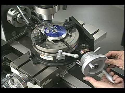
Having a 4-jaw chuck on your rotary table is mighty handy! Because it’s a 4-jaw, you can dial in the workpiece by adjusting the jaws until it is perfectly concentric with the table’s axis of rotation. The best way is to make an adapter plate that attaches to the back of the chuck in the same way that your lathe does so you can exchange lathe tooling with the rotab. Here is an example:
For the example, the chuck is threaded onto the adaptor plate, and then the holes in the adapter plate’s flange are used to bolt down to T-nuts on the table.
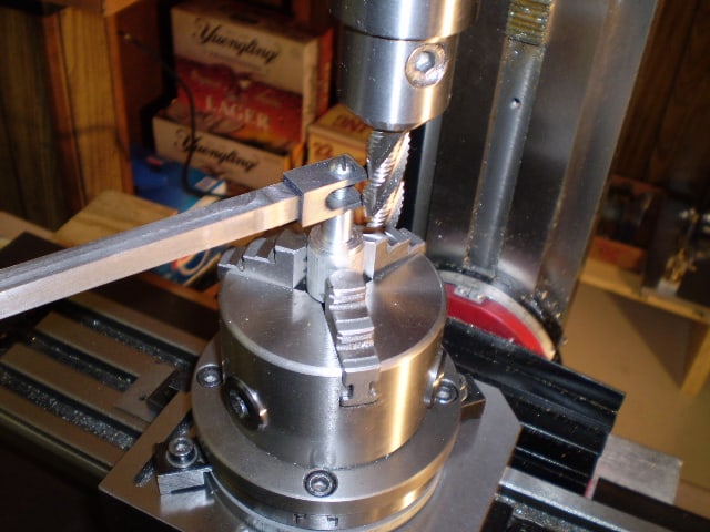
In my case, I bought a 4-jaw from Shars brand new, and simply drilled some through-holes in the chuck to mount to the table directly without an adapter plate:
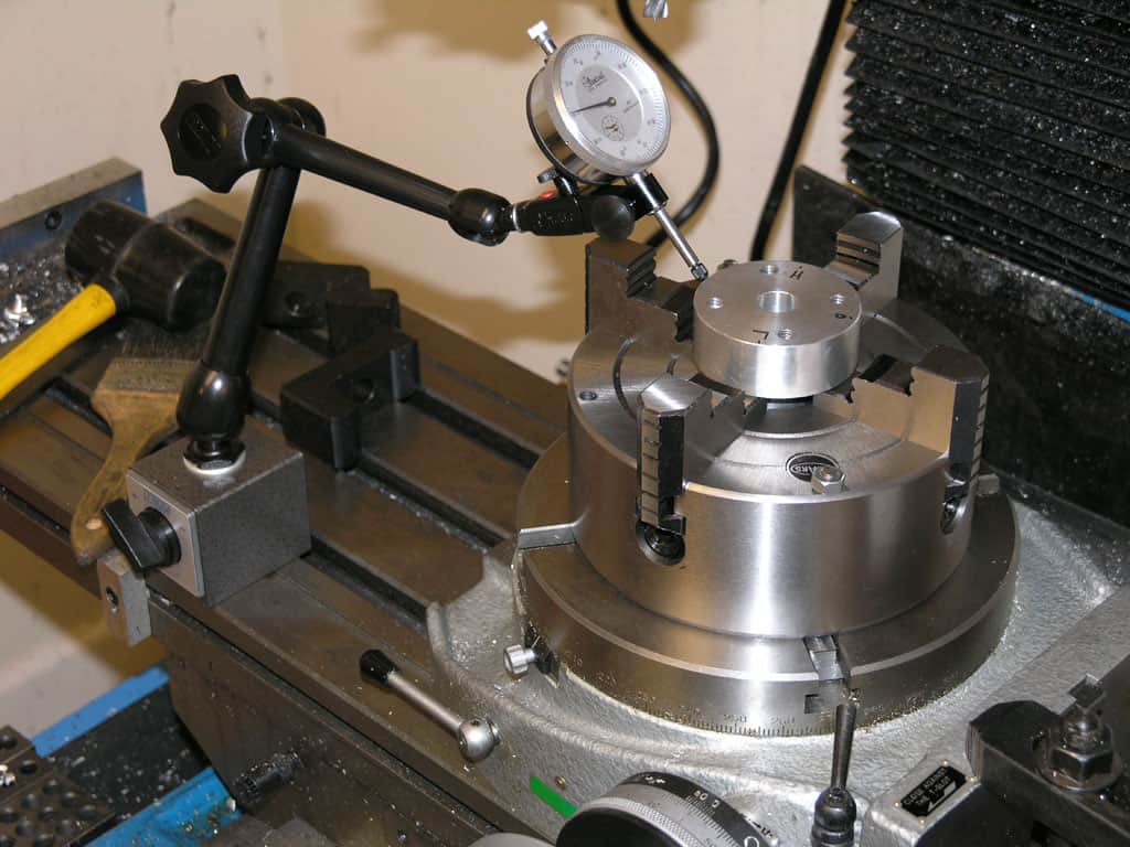
First, you want to make sure your part is properly centered on the table. To do that, I clamp the table down on the mill table (no special place is needed), put my Indicol indicator holder on the mill spindle, and find some round feature on the part to indicate on. For example, on the plate milling fixture above, indicate on the round boss, or on the center hole. Spin the table and bump the part in until spinning the table doesn’t move the indicator.
Second, locate the center of rotation directly under the mill spindle. You can simply use the X and Y table handwheels to do this. Use that Indicol to indicate off of a circular feature you want centered under the spindle. Turn the indicol around on the spindle and adjust the handwheels until the indicator stays put relative to the spindle position. A Blake Coaxial indicator will make this last even simpler.
When you’re rounding partially by cranking a part around on the rotary table, it’s really easy to go a little too far and screw things up. The answer is to drill the end points to make the exact stopping point on the rotab a lot less sensitive:
Centering with a Blake indicator is really fast, but what if you don’t have a Blake, or worse, what if your mill is too small to accomodate one? Here is a nice solution I found on a German site. This fellow has made an ER collect fixture for his rotary table, and has taken care that when installed on the table, the axis of the collet is aligned with the table’s axis. He can then place a dowel or other straight pin in the collet and line up until it will go into a similarly sized collet on the spindle. Nice trick! It’s similar to how Widgitmaster showed me to align a drill chuck on a QCTP to the lathe centerline with a dowel pin held in the lathe chuck.
I usually get a good many arguments started about rotary table setups. I worked in a large forge die shop, and I still do the setups the way we were shown in that shop. Probably 95% of the time you used a rotary table on a rotary head milling machine, so getting stuff on center was step #1.
The first thing to be pointed out is that the center hole and OD of the table aren"t necessarily on the axis of rotation. Easy to check, take the worm out of engagement and pull the table around by hand with an indicator zeroed on the center hole. Just like indicating a part in a four jaw.
If it is on center, that"s great. If not, you can eyeball your part on center and lightly clamp while you indicate it in by pulling the table around by hand and tapping it. If you don"t have a concentric hole or OD to use an indicator on, a center punch mark and a pump center can be used.
Once the part is on the center of the rotary tables axis, it"s a simple matter to center it under the machine spindle by locking the table and rotating the machine spindle and indicating like you would normally.

Prop 65 Warning(s)Many metalworking products contain chemicals or metals included in the latest Prop 65 warning. Exposure may cause cancer and reproductive harm. KBC is currently gathering required California Prop 65 warnings for our customers. For more information go to www.P65Warnings.ca.gov

Run the quill down and touch the sharpie to the rotary table table and by moving the mill table (cross feed) draw a line that will be parallel to the work.....
Now, use an indicator to final align the edge of the plate to be true to the machine ........Do this by rotating the table....Be sure to make all corrections by turning hand wheel in the direction that you will
If you have a moveable degree pointer for the table also set it to zero (most have some adjustment here)....If that is not available on your table make a simple sheet steel pointer plate that is just plain(no pointer.
Move to and cut features as needed...be sure to account for backlash in the table worm...(The starting point for the rotary cuts need to be positioned by moving in the direction you moved to set the plate to zero.)...

I watched a show and the operation was milled just as nice as if turned on a lathe. TV though. They dont show all the set up for the rotary table before hand. My lathe is ready to turn concentric.
Makes me think I am in that place where the machine is always better than you. My mill and lathe have much more potential than I can figure out. In a round about way that gives me a good feeling. I really could make do with just one lathe and one mill.
What impresses me most about some old timers that I know owning job shops or full on CNC station shop. Is the set-ups. I think fixturing is an art, call me crazy. Some folks just have that creative side that says "Yes, I can machine that", no matter the configuration.
New: A brand-new, unused, unopened, undamaged item in its original packaging (where packaging is applicable). Packaging should be the same as what is found in a retail store, unless the item was packaged by the manufacturer in non-retail packaging, such as an unprinted box or plastic bag. See the seller"s listing for full details.See all condition definitionsopens in a new window or tab

Our dealer and auctioneer members offer the most extensive selection of used machinery in the world, with thousands of machines available in warehouses and plants across the globe.
Corporate Address :ABM TOOLS, 79-A, Block GG-1, Vikas Puri,New Delhi – 110018, IndiaFactory Address :Plot No 132/6, Block RZ-Q, Nihal Vihar, Gurudwara Road,Near 500 Sq. Yard Gurudwara, Opp Bharat Properties , Nangloi,Delhi – 110041, IndiaMobile / whatsapp : +91 98910 27608

The rotary table is simply a round flat surface that can be rotated. What makes it interesting is that the table is driven round using a worm and wormwheel arrangement. This means that if a workpiece is mounted on the table it can be machined as it rotates.
On a rotary table the ratio between the worm and wheel is often about 40:1 on a small table but increases with the size of the table. For example a 360mm (12-inch) table might have a ratio of 120:1.
Rotary tables are calibrated round the edge in degrees and have a handle which turns the worm and which, in turn, will rotate the table by 360º divided by the ratio of the worm and wheel. For example, a 360mm (12-inch) table with a 120:1 worm and wheel will rotate by 3º per turn. The handle mechanism has a rotating dial and a Vernier so the angle, on a larger rotary table, can be measured to a few minutes.
Naturally any worm and wheel arrangement on a rotary table is likely to have some backlash. Sometimes this can be compensated for by adjusting the distance between the worm and wheel. Usually any backlash can be ignored if the movement, when machining, is always one way.
The same mechanism can sometimes be used to disengage the worm from the wormwheel. This is useful on large rotary tables because it enables the user to turn the wheel quickly to get from one position to another. (It is not possible to machine the workpiece whilst doing this.)
All rotary tables have a hole in the middle of the table. This is usually a parallel-sided hole but some, especially on smaller rotary tables it is tapered.
This hole can be used to take spigots that can be used to align the rotary table or align the workpiece on the table. Sometimes it is possible to fit a bolt through this hole using various spacers, washers, etc to hold the workpiece on the rotary table.
It is possible the get a device that has a taper on one end that is designed to fit the taper as found on some small rotary tables. The other end has a thread that is designed to fit the backplate as used on the chucks used on some lathes.
All rotary tables can be mounted in the horizontal position on the milling table. Some are designed so they can also be mounted vertically without any other hardware.
Most have slots in the base so they can be bolted to the milling table. Some do not but have a flange so that they can be clamped to the milling table.
It is possible to buy rotary tables that have the facility to tilt the table built in to them. Some even can be tilted at any angle in either or both of two planes at right angles. But all of this adds significantly to the height and weight of the rotary table.
The usefulness of being able to tilt in two planes is very limited and would probably not justify the space it would take up. But a rotary table that tilts in one plane can be useful. This setup can easily be emulated by fitting a rotary table to a tilting table.
Most rotary tables have some means of locking the table at any particular position. Very often an operation is done whilst the table is being rotated in which case the force of the cutter cancels any backlash. However when an operation such as drilling is being done at a particular point then the table should be locked.
Very often a cut needs to be made between two points at the ends of a particular arc. Usually it is not possible to make the cut in one go but several passes are needed. In this case it is useful to have two stops so each cut will start and stop at exactly the same points. This is very useful for preventing mistakes.
The fig. shows a stop. The movable part clamps to the top of the rotary table’s table. Two of these are needed. The fixed part has been fitted to the hole normally used for the locking mechanism as shown in the previous fig.
It will be noticed that the same hole on the rotary table is used for both locking and for a stop. But, of course, in practice, it will, at any one time, only be needed for one function or the other.
For milling any particular workpiece on a rotary table one has to allow for the space around the workpiece for the clamps used to hold it. For example a 200mm rotary table might hold a workpiece that had to have 120mm hole cut into it. It will be shown later how to effectively extend the diameter of a rotary table. It is often desirable to get the largest rotary table that will fit the milling machine table. However larger rotary tables can be very heavy.
With a large milling machine the practical limit is probably the largest you can lift safely. It is possible to have some sort of lifting gear but this all takes time. It is worth looking carefully before buying because for a given diameter, different makes or different methods of construction can cause a rotary table to vary dramatically in weight.
There will usually be enough space between to milling table and the cutting tool to fit a rotary table to do any required job. But there is always the height of the workpiece to consider. If other devices are to be mounted on the rotary table then the space rapidly disappears.
Most rotary table are set up as shown above to be rotated by a certain number of degrees. This is done using the calibrations on the table marked in degrees.
If it is necessary, when using a rotary table to divide a circle into a number of equal sectors then it is necessary to divide 360º by the number of sectors required. On a small rotary table, the table might only be calibrated to 5°. On larger ones they might be calibrated to individual degrees round the edge but will have a vernier arrangement on the handle so they can be set to a certain number of minutes. This gives us the angle between the sectors. Each time we move from one sector to the next we have to add the angle per sector onto the last angle. For any but the simplest numbers, the chances of getting this right are not great.
It is possible to have dividing plates fitted to a rotating table, as shown above, but this is unusual. But since dividing plates are always fitted to dividing heads these will be covered under dividing heads.
It is quite common to need to be able to divide a circle into so many parts. With dividing plates this is easy and is covered elsewhere. for a rotary table using just degrees and minutes a circle can be divided by one of the following methods.
A calculate the angle in your head or using a calculator for the origin for each sector and write them down. Most simple calculators will give decimal angles whereas the rotary table is marked in degrees and minutes.
B use a spreadsheet to produce a list of angles. These will probably be decimal angles. But is then quite easy to turn decimal degrees into degrees and minutes.
C Use tables showing the angles for each position for a circle divided up to 200 sectors can be found in Appendix C. These are in degrees and minutes.
D use the table for the first 200 sectors that can be found in “Tables for [the] Cooke Optical Dividing Head” published by Cooke, Troughton and Simms.


 8613371530291