
how to use a rotary table on a mill free sample

Years ago, before I learned CNC, I owned a Phase II 8″ horizontal/vertical rotary table that I purchased from Kap Pullen’s Getmachinetools.com store. He has them at a good price, BTW, and he’s a darned nice fellow to deal with as well as being a frequent HSM contributor. Anyway, its a nice little table, but I hadn’t done a whole lot with it for quite a while after purchasing it. As is so often the case, one day, a project landed on my doorstep and I was glad to have it.
Before I could get started, however, I had to make some accessories for it. Basically, I needed some T-Nuts to fit the table, as well as a little fixture that makes it easy to hold a plate up off the table through a hole in the center so you can machine it. The latter, what I call a “plate machining fixture”, was inspired by something similar I saw the Widgitmaster of CNCZone fame using to make Dremel clamps for his mini-router:
The Plate Maching Fixture and 3 Homemade T-Nuts. T-Nuts are easy to make: square a block to the proper dimensions, mill the side reliefs, drill, and tap. These are much smaller than the mill’s Bridgeport standard T-slots, so I made them myself and I’m using 1/4-20 bolts with them. They’re made of mild steel.
I turned the round spigot using the 4-jaw on the lathe. I’m making the fixture out of MIC-6 aluminum plate, which is pre-ground very flat on the sides. This is a 5 inch by 3 inch piece. I’ve clamped it to the rotab using my T-nuts and the regular mill clamps and step blocks. It is sitting on parallels to make sure I don’t cut into the table. You can also see how I’ve clamped the rotary table to the mill table using a big cast iron V-block I have. You can never have to many blocks with precision faces hanging around!
Having a 4-jaw chuck on your rotary table is mighty handy! Because it’s a 4-jaw, you can dial in the workpiece by adjusting the jaws until it is perfectly concentric with the table’s axis of rotation. The best way is to make an adapter plate that attaches to the back of the chuck in the same way that your lathe does so you can exchange lathe tooling with the rotab. Here is an example:
For the example, the chuck is threaded onto the adaptor plate, and then the holes in the adapter plate’s flange are used to bolt down to T-nuts on the table.
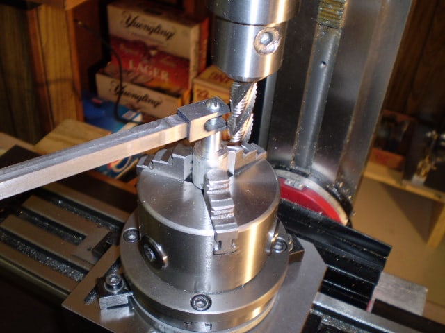
In my case, I bought a 4-jaw from Shars brand new, and simply drilled some through-holes in the chuck to mount to the table directly without an adapter plate:
First, you want to make sure your part is properly centered on the table. To do that, I clamp the table down on the mill table (no special place is needed), put my Indicol indicator holder on the mill spindle, and find some round feature on the part to indicate on. For example, on the plate milling fixture above, indicate on the round boss, or on the center hole. Spin the table and bump the part in until spinning the table doesn’t move the indicator.
Second, locate the center of rotation directly under the mill spindle. You can simply use the X and Y table handwheels to do this. Use that Indicol to indicate off of a circular feature you want centered under the spindle. Turn the indicol around on the spindle and adjust the handwheels until the indicator stays put relative to the spindle position. A Blake Coaxial indicator will make this last even simpler.
When you’re rounding partially by cranking a part around on the rotary table, it’s really easy to go a little too far and screw things up. The answer is to drill the end points to make the exact stopping point on the rotab a lot less sensitive:
Centering with a Blake indicator is really fast, but what if you don’t have a Blake, or worse, what if your mill is too small to accomodate one? Here is a nice solution I found on a German site. This fellow has made an ER collect fixture for his rotary table, and has taken care that when installed on the table, the axis of the collet is aligned with the table’s axis. He can then place a dowel or other straight pin in the collet and line up until it will go into a similarly sized collet on the spindle. Nice trick! It’s similar to how Widgitmaster showed me to align a drill chuck on a QCTP to the lathe centerline with a dowel pin held in the lathe chuck.

The crosslide table all depends on where the slides are...above the point of rotation or below. Below is pretty much the cheap line and really is redundant putting on a mill as you already have 2 axis there. Now, slides above the pivot point allows you to position your part any where on table, center it above the pivot using the slides (U & V axis?) all with out tapping it about like a rotary table w/o slides. Also, you can then offset a part to center a desired radius elsewhere...example: you need to mill a 4" square hole with r.535 in corners. On a plain rotary table you would need to relocate the part for each corner...with topslides you use the U & V axis to position the center of R.535 over the pivot and turn the corner. This works for all kinds of stuff...milling angles off the X&Y that come tang to a rad, or even milling multiple circles or countours on a single pc w/o remounting and locating the pc. Think of 3 O-ring grooves on a hydraulic cover, or the snowman shape in a gearpump hsg. These can get confusing as now you have a manual machine with C,U,V,W,X,Y,&Z axis....wow.
The best has to be Advance 15X15. I know this unit cost $4500 15 years ago.Troyke made them also but I don"t know of others. Palmgren I thought made the bottom slide type. Alas, the 2axis CNC retros can outrun it and these are rapidly becoming dinosaurs.
This website or its third-party tools process personal data (e.g. browsing data or IP addresses) and use cookies or other identifiers, which are necessary for its functioning and required to achieve the purposes illustrated in the cookie policy. To learn more, please refer to the cookie policy. In case of sale of your personal information, you may opt out by sending us an email via our Contact Us page. To find out more about the categories of personal information collected and the purposes for which such information will be used, please refer to our privacy policy. You accept the use of cookies or other identifiers by closing or dismissing this notice, by scrolling this page, by clicking a link or button or by continuing to browse otherwise.

I usually get a good many arguments started about rotary table setups. I worked in a large forge die shop, and I still do the setups the way we were shown in that shop. Probably 95% of the time you used a rotary table on a rotary head milling machine, so getting stuff on center was step #1.
The first thing to be pointed out is that the center hole and OD of the table aren"t necessarily on the axis of rotation. Easy to check, take the worm out of engagement and pull the table around by hand with an indicator zeroed on the center hole. Just like indicating a part in a four jaw.
If it is on center, that"s great. If not, you can eyeball your part on center and lightly clamp while you indicate it in by pulling the table around by hand and tapping it. If you don"t have a concentric hole or OD to use an indicator on, a center punch mark and a pump center can be used.
Once the part is on the center of the rotary tables axis, it"s a simple matter to center it under the machine spindle by locking the table and rotating the machine spindle and indicating like you would normally.

Milling can be done with a wide range of machine tools. The original class of machine tools for milling was the milling machine (often called a mill). After the advent of computer numerical control (CNC) in the 1960s, milling machines evolved into machining centers: milling machines augmented by automatic tool changers, tool magazines or carousels, CNC capability, coolant systems, and enclosures. Milling centers are generally classified as vertical machining centers (VMCs) or horizontal machining centers (HMCs).
The integration of milling into turning environments, and vice versa, began with live tooling for lathes and the occasional use of mills for turning operations. This led to a new class of machine tools, multitasking machines (MTMs), which are purpose-built to facilitate milling and turning within the same work envelope.
Milling is a cutting process that uses a milling cutter to remove material from the surface of a work piece. The milling cutter is a rotary cutting tool, often with multiple cutting points. As opposed to drilling, where the tool is advanced along its rotation axis, the cutter in milling is usually moved perpendicular to its axis so that cutting occurs on the circumference of the cutter. As the milling cutter enters the work piece, the cutting edges (flutes or teeth) of the tool repeatedly cut into and exit from the material, shaving off chips (swarf) from the work piece with each pass. The cutting action is shear deformation; material is pushed off the work piece in tiny clumps that hang together to a greater or lesser extent (depending on the material) to form chips. This makes metal cutting somewhat different (in its mechanics) from slicing softer materials with a blade.
The milling process removes material by performing many separate, small cuts. This is accomplished by using a cutter with many teeth, spinning the cutter at high speed, or advancing the material through the cutter slowly; most often it is some combination of these three approaches.speeds and feeds used are varied to suit a combination of variables. The speed at which the piece advances through the cutter is called feed rate, or just feed; it is most often measured as distance per time (inches per minute [in/min or ipm] or millimeters per minute [mm/min]), although distance per revolution or per cutter tooth are also sometimes used.
In face milling, the cutting action occurs primarily at the end corners of the milling cutter. Face milling is used to cut flat surfaces (faces) into the work piece, or to cut flat-bottomed cavities.
In peripheral milling, the cutting action occurs primarily along the circumference of the cutter, so that the cross section of the milled surface ends up receiving the shape of the cutter. In this case the blades of the cutter can be seen as scooping out material from the work piece. Peripheral milling is well suited to the cutting of deep slots, threads, and gear teeth.
Many different types of cutting tools are used in the milling process. Milling cutters such as end mills may have cutting surfaces across their entire end surface, so that they can be drilled into the work piece (plunging). Milling cutters may also have extended cutting surfaces on their sides to allow for peripheral milling. Tools optimized for face milling tend to have only small cutters at their end corners.
The cutting surfaces of a milling cutter are generally made of a hard and temperature-resistant material, so that they wear slowly. A low cost cutter may have surfaces made of high speed steel. More expensive but slower-wearing materials include cemented carbide. Thin film coatings may be applied to decrease friction or further increase hardness.
There are cutting tools typically used in milling machines or machining centers to perform milling operations (and occasionally in other machine tools). They remove material by their movement within the machine (e.g., a ball nose mill) or directly from the cutter"s shape (e.g., a form tool such as a hobbing cutter).
A diagram of revolution ridges on a surface milled by the side of the cutter, showing the position of the cutter for each cutting pass and how it corresponds with the ridges (cutter rotation axis is perpendicular to image plane)
As material passes through the cutting area of a milling machine, the blades of the cutter take swarfs of material at regular intervals. Surfaces cut by the side of the cutter (as in peripheral milling) therefore always contain regular ridges. The distance between ridges and the height of the ridges depend on the feed rate, number of cutting surfaces, the cutter diameter.surface finish.
The face milling process can in principle produce very flat surfaces. However, in practice the result always shows visible trochoidal marks following the motion of points on the cutter"s end face. These revolution marks give the characteristic finish of a face milled surface. Revolution marks can have significant roughness depending on factors such as flatness of the cutter"s end face and the degree of perpendicularity between the cutter"s rotation axis and feed direction. Often a final pass with a slow feed rate is used to improve the surface finish after the bulk of the material has been removed. In a precise face milling operation, the revolution marks will only be microscopic scratches due to imperfections in the cutting edge.
Gang milling refers to the use of two or more milling cutters mounted on the same arbor (that is, ganged) in a horizontal-milling setup. All of the cutters may perform the same type of operation, or each cutter may perform a different type of operation. For example, if several workpieces need a slot, a flat surface, and an angular groove, a good method to cut these (within a non-CNC context) would be gang milling. All the completed workpieces would be the same, and milling time per piece would be minimized.
Gang milling was especially important before the CNC era, because for duplicate part production, it was a substantial efficiency improvement over manual-milling one feature at an operation, then changing machines (or changing setup of the same machine) to cut the next op. Today, CNC mills with automatic tool change and 4- or 5-axis control obviate gang-milling practice to a large extent.
Mill orientation is the primary classification for milling machines. The two basic configurations are vertical and horizontal – referring to the orientation of the rotating spindle upon which the cutter is mounted. However, there are alternative classifications according to method of control, size, purpose and power source.
In the vertical milling machine the spindle axis is vertically oriented. Milling cutters are held in the spindle and rotate on its axis. The spindle can generally be lowered (or the table can be raised, giving the same relative effect of bringing the cutter closer or deeper into the work), allowing plunge cuts and drilling. The depth to which blades cut into the work can be controlled with a micrometer adjustment nut. There are two subcategories of vertical mills: the bed mill and the turret mill.
A turret mill has a fixed spindle and the table is moved both perpendicular and parallel to the spindle axis to accomplish cutting. Some turret mills have a quill which allows the milling cutter (or a drill) to be raised and lowered in a manner similar to a drill press. This provides two methods of cutting in the vertical (Z) direction: by raising or lowering the quill, and by moving the knee.
A third type also exists, a lighter, more versatile machine, called a mill-drill. The mill-drill is a close relative of the vertical mill and quite popular in light industry; and with hobbyists. A mill-drill is similar in basic configuration to a very heavy drill press, but equipped with an X-Y table and a much larger column. They also typically use more powerful motors than a comparably sized drill press, most are muti-speed belt driven with some models having a geared head or electronic speed control. They generally have quite heavy-duty spindle bearings to deal with the lateral loading on the spindle that is created by a milling operation. A mill drill also typically raises and lowers the entire head, including motor, often on a dovetailed (sometimes round with rack and pinion) vertical column. A mill drill also has a large quill that is generally locked during milling operations and released to facilitate drilling functions. Other differences that separate a mill-drill from a drill press may be a fine tuning adjustment for the Z-axis, a more precise depth stop, the capability to lock the X, Y or Z axis, and often a system of tilting the head or the entire vertical column and powerhead assembly to allow angled cutting-drilling. Aside from size, the principal difference between these lighter machines and larger vertical mills is that the X-Y table is at a fixed elevation; the Z-axis is controlled by moving the head or quill down toward the X,Y table. A mill drill typically has an internal taper fitting in the quill to take a collet chuck, face mills, or a Jacobs chuck similar to the vertical mill.
A horizontal mill has the same sort but the cutters are mounted on a horizontal spindle, or arbor, mounted across the table. Many horizontal mills also feature a built-in rotary table that allows milling at various angles; this feature is called a universal table. While endmills and the other types of tools available to a vertical mill may be used in a horizontal mill, their real advantage lies in arbor-mounted cutters, called side and face mills, which have a cross section rather like a circular saw, but are generally wider and smaller in diameter. Because the cutters have good support from the arbor and have a larger cross-sectional area than an end mill, quite heavy cuts can be taken enabling rapid material removal rates. These are used to mill grooves and slots. Plain mills are used to shape flat surfaces. Several cutters may be ganged together on the arbor to mill a complex shape of slots and planes. Special cutters can also cut grooves, bevels, radii, or indeed any section desired. These specialty cutters tend to be expensive. Simplex mills have one spindle, and duplex mills have two. It is also easier to cut gears on a horizontal mill. Some horizontal milling machines are equipped with a power-take-off provision on the table. This allows the table feed to be synchronized to a rotary fixture, enabling the milling of spiral features such as hypoid gears.
Is a milling machine with the facility to either have a horizontal spindle or a vertical spindle. The latter sometimes being on a two-axis turret enabling the spindle to be pointed in any direction on desires. The two options may be driven independently or from one motor through gearing. In either case, as the work is generally placed in the same place for either type of operation, the mechanism for the method not being used is moved out of the way. In smaller machines, "spares" may be lifted off while larger machines offer a system to retract those parts not in use.
The choice between vertical and horizontal spindle orientation in milling machine design usually hinges on the shape and size of a workpiece and the number of sides of the workpiece that require machining. Work in which the spindle"s axial movement is normal to one plane, with an endmill as the cutter, lends itself to a vertical mill, where the operator can stand before the machine and have easy access to the cutting action by looking down upon it. Thus vertical mills are most favored for diesinking work (machining a mould into a block of metal).
Prior to numerical control, horizontal milling machines evolved first, because they evolved by putting milling tables under lathe-like headstocks. Vertical mills appeared in subsequent decades, and accessories in the form of add-on heads to change horizontal mills to vertical mills (and later vice versa) have been commonly used. Even in the CNC era, a heavy workpiece needing machining on multiple sides lends itself to a horizontal machining center, while diesinking lends itself to a vertical one.
Among vertical mills, "Bridgeport-style" is a whole class of mills inspired by the Bridgeport original, rather like the IBM PC spawned the industry of IBM-compatible PCs by other brands
A distinction whose meaning evolved over decades as technology progressed, and overlaps with other purpose classifications above. Not relevant to today"s CNC mills. Regarding manual mills, the common theme is that "plain" mills were production machines with fewer axes than "universal" mills; for example, whereas a plain mill had no indexing head and a non-rotating table, a universal mill would have those. Thus it was suited to universal service, that is, a wider range of possible toolpaths. Machine tool builders no longer use the "plain"-versus-"universal" labeling.
Bed mill This refers to any milling machine where the spindle is on a pendant that moves up and down to move the cutter into the work, while the table sits on a stout bed that rests on the floor. These are generally more rigid than a knee mill. Gantry mills can be included in this bed mill category.
C-frame mill These are larger, industrial production mills. They feature a knee and fixed spindle head that is only mobile vertically. They are typically much more powerful than a turret mill, featuring a separate hydraulic motor for integral hydraulic power feeds in all directions, and a twenty to fifty horsepower motor. Backlash eliminators are almost always standard equipment. They use large NMTB 40 or 50 tooling. The tables on C-frame mills are usually 18" by 68" or larger, to allow multiple parts to be machined at the same time.
Floor mill These have a row of rotary tables, and a horizontal pendant spindle mounted on a set of tracks that runs parallel to the table row. These mills have predominantly been converted to CNC, but some can still be found (if one can even find a used machine available) under manual control. The spindle carriage moves to each individual table, performs the machining operations, and moves to the next table while the previous table is being set up for the next operation. Unlike other mills, floor mills have movable floor units. A crane drops massive rotary tables, X-Y tables, etc., into position for machining, allowing large and complex custom milling operations.
Gantry mill The milling head rides over two rails (often steel shafts) which lie at each side of the work surface. Due to its design it usually has a very small footprint compared to the machine travel size. As a downside they are usually not as rigid as e.g. C-Frame mills.
Horizontal boring mill Large, accurate bed horizontal mills that incorporate many features from various machine tools. They are predominantly used to create large manufacturing jigs, or to modify large, high precision parts. They have a spindle stroke of several (usually between four and six) feet, and many are equipped with a tailstock to perform very long boring operations without losing accuracy as the bore increases in depth. A typical bed has X and Y travel, and is between three and four feet square with a rotary table or a larger rectangle without a table. The pendant usually provides between four and eight feet of vertical movement. Some mills have a large (30" or more) integral facing head. Right angle rotary tables and vertical milling attachments are available for further flexibility.
Knee mill or knee-and-column mill refers to any milling machine whose x-y table rides up and down the column on a vertically adjustable knee. This includes Bridgeports.
Planer-style mill (Plano Milling)Large mills built in the same configuration as planers except with a milling spindle instead of a planing head. This term is growing dated as planers themselves are largely a thing of the past.
Ram-type mill This can refer to any mill that has a cutting head mounted on a sliding ram. The spindle can be oriented either vertically or horizontally. In practice most mills with rams also involve swiveling ability, whether or not it is called "turret" mounting. The Bridgeport configuration can be classified as a vertical-head ram-type mill. Van Norman Machine Tool Company specialized in ram-type mills through most of the 20th century. Since the wide dissemination of CNC machines, ram-type mills are still made in the Bridgeport configuration (with either manual or CNC control), but the less common variations (such as were built by Van Norman, Index, and others) have died out, their work being done now by either Bridgeport-form mills or machining centers.
Turret mill More commonly referred to as Bridgeport-type milling machines. The spindle can be aligned in many different positions for a very versatile, if somewhat less rigid machine.
Since the 1960s there has developed an overlap of usage between the terms milling machine and machining center. NC/CNC machining centers evolved from milling machines, which is why the terminology evolved gradually with considerable overlap that still persists. The distinction, when one is made, is that a machining center is a mill with features that pre-CNC mills never had, especially an automatic tool changer (ATC) that includes a tool magazine (carousel), and sometimes an automatic pallet changer (APC). In typical usage, all machining centers are mills, but not all mills are machining centers; only mills with ATCs are machining centers.
Most CNC milling machines (also called machining centers) are computer controlled vertical mills with the ability to move the spindle vertically along the Z-axis. This extra degree of freedom permits their use in diesinking, engraving applications, and 2.5D surfaces such as relief sculptures. When combined with the use of conical tools or a ball nose cutter, it also significantly improves milling precision without impacting speed, providing a cost-efficient alternative to most flat-surface hand-engraving work.
CNC machines can exist in virtually any of the forms of manual machinery, like horizontal mills. The most advanced CNC milling-machines, the multiaxis machine, add two more axes in addition to the three normal axes (XYZ). Horizontal milling machines also have a C or Q axis, allowing the horizontally mounted workpiece to be rotated, essentially allowing asymmetric and eccentric turning. The fifth axis (B axis) controls the tilt of the tool itself. When all of these axes are used in conjunction with each other, extremely complicated geometries, even organic geometries such as a human head can be made with relative ease with these machines. But the skill to program such geometries is beyond that of most operators. Therefore, 5-axis milling machines are practically always programmed with CAM.
These machines have developed from the basic NC (NUMERIC CONTROL) machines. A computerized form of NC machines is known as CNC machines. A set of instructions (called a program) is used to guide the machine for desired operations. Some very commonly used codes, which are used in the program are:
Various other codes are also used. A CNC machine is operated by a single operator called a programmer. This machine is capable of performing various operations automatically and economically.
The accessories and cutting tools used on machine tools (including milling machines) are referred to in aggregate by the mass noun "tooling". There is a high degree of standardization of the tooling used with CNC milling machines, and a lesser degree with manual milling machines. To ease up the organization of the tooling in CNC production many companies use a tool management solution.
CNC milling machines nearly always use SK (or ISO), CAT, BT or HSK tooling. SK tooling is the most common in Europe, while CAT tooling, sometimes called V-Flange Tooling, is the oldest and probably most common type in the USA. CAT tooling was invented by Caterpillar Inc. of Peoria, Illinois, in order to standardize the tooling used on their machinery. CAT tooling comes in a range of sizes designated as CAT-30, CAT-40, CAT-50, etc. The number refers to the Association for Manufacturing Technology (formerly the National Machine Tool Builders Association (NMTB)) taper size of the tool.
An improvement on CAT Tooling is BT Tooling, which looks similar and can easily be confused with CAT tooling. Like CAT Tooling, BT Tooling comes in a range of sizes and uses the same NMTB body taper. However, BT tooling is symmetrical about the spindle axis, which CAT tooling is not. This gives BT tooling greater stability and balance at high speeds. One other subtle difference between these two toolholders is the thread used to hold the pull stud. CAT Tooling is all Imperial thread and BT Tooling is all Metric thread. Note that this affects the pull stud only; it does not affect the tool that they can hold. Both types of tooling are sold to accept both Imperial and metric sized tools.
SK and HSK tooling, sometimes called "Hollow Shank Tooling", is much more common in Europe where it was invented than it is in the United States. It is claimed that HSK tooling is even better than BT Tooling at high speeds. The holding mechanism for HSK tooling is placed within the (hollow) body of the tool and, as spindle speed increases, it expands, gripping the tool more tightly with increasing spindle speed. There is no pull stud with this type of tooling.
For manual milling machines, there is less standardization, because a greater plurality of formerly competing standards exist. Newer and larger manual machines usually use NMTB tooling. This tooling is somewhat similar to CAT tooling but requires a drawbar within the milling machine. Furthermore, there are a number of variations with NMTB tooling that make interchangeability troublesome. The older a machine, the greater the plurality of standards that may apply (e.g., Morse, Jarno, Brown & Sharpe, Van Norman, and other less common builder-specific tapers). However, two standards that have seen especially wide usage are the Morse #2 and the R8, whose prevalence was driven by the popularity of the mills built by Bridgeport Machines of Bridgeport, Connecticut. These mills so dominated the market for such a long time that "Bridgeport" is virtually synonymous with "manual milling machine". Most of the machines that Bridgeport made between 1938 and 1965 used a Morse taper #2, and from about 1965 onward most used an R8 taper.
Pocket milling has been regarded as one of the most widely used operations in machining. It is extensively used in aerospace and shipyard industries. In pocket milling the material inside an arbitrarily closed boundary on a flat surface of a work piece is removed to a fixed depth. Generally flat bottom end mills are used for pocket milling. Firstly roughing operation is done to remove the bulk of material and then the pocket is finished by a finish end mill.2.5 axis CNC milling. This type of path control can machine up to 80% of all mechanical parts. Since the importance of pocket milling is very relevant, therefore effective pocketing approaches can result in reduction in machining time and cost.NC pocket milling can be carried out mainly by two tool paths, viz. linear and non-linear.
In zig-zag milling, material is removed both in forward and backward paths. In this case, cutting is done both with and against the rotation of the spindle. This reduces the machining time but increases machine chatter and tool wear.
In zig milling, the tool moves only in one direction. The tool has to be lifted and retracted after each cut, due to which machining time increases. However, in case of zig milling surface quality is better.
In this approach, the required pocket boundary is used to derive the tool path. In this case the cutter is always in contact with the work material. Hence the idle time spent in positioning and retracting the tool is avoided. For large-scale material removal, contour-parallel tool path is widely used because it can be consistently used with up-cut or down-cut method during the entire process. There are three different approaches that fall into the category of contour-parallel tool path generation. They are:
Pair-wise intersection approach:In pair-wise intersection approach, the boundary of the pocket is brought inwards in steps, The offset segments will intersect at concave corners. To obtain the required contour, these intersections are to be trimmed off. On the other hand, in case of convex corner, the offset segments are extended and thereby connected to make the contour. These operations viz. offsetting, trimming and extending are repeatedly done to cover the entire machining volume with sufficient layer of profiles.
Voronoi diagram approach: In voronoi diagram approach, the pocket boundary is segmented and voronoi diagram is constructed for the entire pocket boundary. These voronoi diagrams are used for generating the tool path for machining. This method is considered to be more efficient and robust. Moreover, it avoids topological problems associated with traditional offsetting algorithms.
In this approach, the tool travels along a gradually evolving spiral path. The spiral starts at the center of the pocket to be machined and the tool gradually moves towards the pocket boundary. The direction of the tool path changes progressively and local acceleration and deceleration of the tool are minimized. This reduces tool wear.
Milling machines evolved from the practice of rotary filing—that is, running a circular cutter with file-like teeth in the headstock of a lathe. Rotary filing and, later, true milling were developed to reduce time and effort spent hand-filing. The full story of milling machine development may never be known, because much early development took place in individual shops where few records were kept for posterity. However, the broad outlines are known, as summarized below. From a history-of-technology viewpoint, it is clear that the naming of this new type of machining with the term "milling" was an extension from that word"s earlier senses of processing materials by abrading them in some way (cutting, grinding, crushing, etc.).
In 1783 Samuel Rehe invented a true milling machine.Eli Terry began using a milling machine at Plymouth Connecticut in the production of tall case clocks. With the use of his milling machine, Terry was the first to accomplish Interchangeable parts in the clock industry. Milling wooden parts was efficient in interchangeable parts, but inefficient in high yields. Milling wooden blanks results in a low yield of parts because the machines single blade would cause loss of gear teeth when the cutter hit parallel grains in the wood. Terry later invented a spindle cutting machine to mass produce parts in 1807. Other Connecticut clockmakers like James Harrison of Waterbury, Thomas Barnes of Litchfield, and Gideon Roberts of Bristol, also used milling machines to produce their clocks.
This milling machine was long credited to Eli Whitney and dated to circa 1818. From the 1910s through the 1940s, this version of its provenance was widely published. In the 1950s and 1960s, various historians of technology mostly discredited the view of this machine as the first miller and possibly even of Whitney as its builder. Nonetheless, it is still an important early milling machine, regardless of its exact provenance.
It is clear that milling machines as a distinct class of machine tool (separate from lathes running rotary files) first appeared between 1814 and 1818. The centers of earliest development of true milling machines were two federal armories of the U.S. (Springfield and Harpers Ferry) together with the various private armories and inside contractors that shared turnover of skilled workmen with them.
Between 1912 and 1916, Joseph W. Roe, a respected founding father of machine tool historians, credited Eli Whitney (one of the private arms makers mentioned above) with producing the first true milling machine.Middletown, Connecticut; Captain John H. Hall of the Harpers Ferry armory; Simeon North of the Staddle Hill factory in Middletown; Roswell Lee of the Springfield armory; and Thomas Blanchard. (Several of the men mentioned above are sometimes described on the internet as "the inventor of the first milling machine" or "the inventor of interchangeable parts". Such claims are oversimplified, as these technologies evolved over time among many people.)
Peter Baida,Smithsonian Journal of History in 1966, exemplifies the dispelling of the "Great Man" image of Whitney by historians of technology working in the 1950s and 1960s. He quotes Battison as concluding that "There is no evidence that Whitney developed or used a true milling machine." Baida says, "The so-called Whitney machine of 1818 seems actually to have been made after Whitney"s death in 1825." Baida cites Battison"s suggestion that the first true milling machine was made not by Whitney, but by Robert Johnson of Middletown.
The late teens of the 19th century were a pivotal time in the history of machine tools, as the period of 1814 to 1818 is also the period during which several contemporary pioneers (Fox, Murray, and Roberts) were developing the planer,
A milling machine built and used in the shop of Gay & Silver (aka Gay, Silver, & Co) in the 1830s was influential because it employed a better method of vertical positioning than earlier machines. For example, Whitney"s machine (the one that Roe considered the very first) and others did not make provision for vertical travel of the knee. Evidently, the workflow assumption behind this was that the machine would be set up with shims, vise, etc. for a certain part design, and successive parts did not require vertical adjustment (or at most would need only shimming). This indicates that early thinking about milling machines was as production and not as toolroom machines.
In these early years, milling was often viewed as only a roughing operation to be followed by finishing with a hand file. The idea of reducing hand filing was more important than replacing it.
Some of the key men in milling machine development during this era included Frederick W. Howe, Francis A. Pratt, Elisha K. Root, and others. (These same men during the same era were also busy developing the state of the art in turret lathes. Howe"s experience at Gay & Silver in the 1840s acquainted him with early versions of both machine tools. His machine tool designs were later built at Robbins & Lawrence, the Providence Tool Company, and Brown & Sharpe.) The most successful milling machine design to emerge during this era was the Lincoln miller, which rather than being a specific make and model of machine tool is truly a family of tools built by various companies on a common configuration over several decades. It took its name from the first company to put one on the market, George S. Lincoln & Company (formerly the Phoenix Iron Works), whose first one was built in 1855 for the Colt armory.
During this era there was a continued blind spot in milling machine design, as various designers failed to develop a truly simple and effective means of providing slide travel in all three of the archetypal milling axes (X, Y, and Z—or as they were known in the past, longitudinal, traverse, and vertical). Vertical positioning ideas were either absent or underdeveloped. The Lincoln miller"s spindle could be raised and lowered, but the original idea behind its positioning was to be set up in position and then run, as opposed to being moved frequently while running. Like a turret lathe, it was a repetitive-production machine, with each skilled setup followed by extensive fairly low skill operation.
In 1861, Frederick W. Howe, while working for the Providence Tool Company, asked Joseph R. Brown of Brown & Sharpe for a solution to the problem of milling spirals, such as the flutes of twist drills. These were usually filed by hand at the time.Helical planing existed but was by no means common.) Brown designed a "universal milling machine" that, starting from its first sale in March 1862, was wildly successful. It solved the problem of 3-axis travel (i.e., the axes that we now call XYZ) much more elegantly than had been done in the past, and it allowed for the milling of spirals using an indexing head fed in coordination with the table feed. The term "universal" was applied to it because it was ready for any kind of work, including toolroom work, and was not as limited in application as previous designs. (Howe had designed a "universal miller" in 1852, but Brown"s of 1861 is the one considered a groundbreaking success.)
Brown also developed and patented (1864) the design of formed milling cutters in which successive sharpenings of the teeth do not disturb the geometry of the form.
In these decades, Brown & Sharpe and the Cincinnati Milling Machine Company dominated the American milling machine field. However, hundreds of other firms also built milling machines at the time, and many were significant in various ways. Besides a wide variety of specialized production machines, the archetypal multipurpose milling machine of the late 19th and early 20th centuries was a heavy knee-and-column horizontal-spindle design with power table feeds, indexing head, and a stout overarm to support the arbor. The evolution of machine design was driven not only by inventive spirit but also by the constant evolution of milling cutters that saw milestone after milestone from 1860 through World War I.
Around the end of World War I, machine tool control advanced in various ways that laid the groundwork for later CNC technology. The jig borer popularized the ideas of coordinate dimensioning (dimensioning of all locations on the part from a single reference point); working routinely in "tenths" (ten-thousandths of an inch, 0.0001") as an everyday machine capability; and using the control to go straight from drawing to part, circumventing jig-making. In 1920 the new tracer design of J.C. Shaw was applied to Keller tracer milling machines for die sinking via the three dimensional copying of a template. This made die sinking faster and easier just as dies were in higher demand than ever before, and was very helpful for large steel dies such as those used to stamp sheets in automobile manufacturing. Such machines translated the tracer movements to input for servos that worked the machine leadscrews or hydraulics. They also spurred the development of antibacklash leadscrew nuts. All of the above concepts were new in the 1920s but became routine in the NC/CNC era. By the 1930s, incredibly large and advanced milling machines existed, such as the Cincinnati Hydro-Tel, that presaged today"s CNC mills in every respect except for CNC control itself.
In 1936, Rudolph Bannow (1897–1962) conceived of a major improvement to the milling machine.Bridgeport milling machine, often called a ram-type or turret-type mill because its head has sliding-ram and rotating-turret mounting. The machine became so popular that many other manufacturers created copies and variants. Furthermore, its name came to connote any such variant. The Bridgeport offered enduring advantages over previous models. It was small enough, light enough, and affordable enough to be a practical acquisition for even the smallest machine shop businesses, yet it was also smartly designed, versatile, well-built, and rigid. Its various directions of sliding and pivoting movement allowed the head to approach the work from any angle. The Bridgeport"s design became the dominant form for manual milling machines used by several generations of small- and medium-enterprise machinists. By the 1980s an estimated quarter-million Bridgeport milling machines had been built,
By 1940, automation via cams, such as in screw machines and automatic chuckers, had already been very well developed for decades. Beginning in the 1930s, ideas involving servomechanisms had been in the air, but it was especially during and immediately after World War II that they began to germinate (see also Numerical control > History). These were soon combined with the emerging technology of digital computers. This technological development milieu, spanning from the immediate pre–World War II period into the 1950s, was powered by the military capital expenditures that pursued contemporary advancements in the directing of gun and rocket artillery and in missile guidance—other applications in which humans wished to control the kinematics/dynamics of large machines quickly, precisely, and automatically. Sufficient R&D spending probably would not have happened within the machine tool industry alone; but it was for the latter applications that the will and ability to spend was available. Once the development was underway, it was eagerly applied to machine tool control in one of the many post-WWII instances of technology transfer.
In 1952, numerical control reached the developmental stage of laboratory reality. The first NC machine tool was a Cincinnati Hydrotel milling machine retrofitted with a scratch-built NC control unit. It was reported in Scientific American,
During the 1950s, numerical control moved slowly from the laboratory into commercial service. For its first decade, it had rather limited impact outside of aerospace work. But during the 1960s and 1970s, NC evolved into CNC, data storage and input media evolved, computer processing power and memory capacity steadily increased, and NC and CNC machine tools gradually disseminated from an environment of huge corporations and mainly aerospace work to the level of medium-sized corporations and a wide variety of products. NC and CNC"s drastic advancement of machine tool control deeply transformed the culture of manufacturing.
Computers and CNC machine tools continue to develop rapidly. The personal computer revolution has a great impact on this development. By the late 1980s small machine shops had desktop computers and CNC machine tools. Soon after, hobbyists, artists, and designers began obtaining CNC mills and lathes. Manufacturers have started producing economically priced CNCs machines small enough to sit on a desktop which can cut at high resolution materials softer than stainless steel. They can be used to make anything from jewelry to printed circuit boards to gun parts, even fine art.
National and international standards are used to standardize the definitions, environmental requirements, and test methods used for milling. Selection of the standard to be used is an agreement between the supplier and the user and has some significance in the design of the mill. In the United States, ASME has developed the standards B5.45-1972 Milling Machines and B94.19-1997 Milling Cutters and End Mills.
General tolerances include: +/-0.005" for local tolerances across most geometries, +/-0.010" for plastics with variation depending on the size of the part, 0.030" minimum wall thickness for metals, and 0.060" minimum wall thickness for plastics.
Kramer, Thomas R. (1992). "Pocket Milling with Tool Engagement Detection". Journal of Manufacturing Systems. 11 (2): 112–123. CiteSeerX doi:10.1016/0278-6125(92)90042-E.
Held, Martin (1991). "A geometry-based investigation of the tool path generation for zigzag pocket machining". The Visual Computer. 7 (5–6): 296–308. doi:10.1007/BF01905694. S2CID 1057336.
Choy, H.S.; Chan, K.W. (February 2003). "A corner-looping based tool path for pocket milling". Computer-Aided Design. 35 (2): 155–166. doi:10.1016/S0010-4485(02)00049-0.
Hansen, Allan; Arbab, Farhad (April 1992). "An algorithm for generating NC tool paths for arbitrarily shaped pockets with islands". ACM Transactions on Graphics. 11 (2): 152–182. doi:10.1145/130826.130832. S2CID 2388266.
Jeong, J.; Kim, K. (1998). "Tool Path Generation for Machining Free-Form Pockets Voronoi Diagrams". The International Journal of Advanced Manufacturing Technology. 14 (12): 876–881. doi:10.1007/BF01179076. S2CID 109784396.
Bieterman, Michael B.; Sandstrom, Donald R. (Nov 11, 2003). "A Curvilinear Tool-Path Method for Pocket Machining". Journal of Manufacturing Science and Engineering. 125 (4): 709–715. doi:10.1115/1.1596579.
Noble, David F. (1984), Forces of Production: A Social History of Industrial Automation, New York, New York, USA: Knopf, ISBN 978-0-394-51262-4, LCCN 83048867.
. Reprinted by McGraw-Hill, New York and London, 1926 (LCCN 27-24075); and by Lindsay Publications, Inc., Bradley, Illinois (ISBN 978-0-917914-73-7)..
Hounshell, David A. (1984), From the American System to Mass Production, 1800–1932: The Development of Manufacturing Technology in the United States, Baltimore, Maryland: Johns Hopkins University Press, ISBN 978-0-8018-2975-8, LCCN 83016269, OCLC 1104810110

VEVOR is a leading brand that specializes in equipment and tools. Along with thousands of motivated employees, VEVOR is dedicated to providing our customers with tough equipment & tools at incredibly low prices. Today, VEVOR has occupied markets of more than 200 countries with 10 million plus global members.
VEVOR is a leading brand that specializes in equipment and tools. Along with thousands of motivated employees, VEVOR is dedicated to providing our customers with tough equipment & tools at incredibly low prices. Today, VEVOR has occupied markets of more than 200 countries with 10 million plus global members.
The mill rotary table is one of the main accessories of milling machine. As a precision work positioning device, it is widely used for indexing drilling, milling, circumferential cutting, boring, etc. The rotary turn table for milling machine is made from HT200 casting with high quality. It has already passed the ISO9001 quality system certification. They are are very popular on the market for their superior performance, excellent design and reasonable cost.
Both vertical and horizontal with two functions. Circle cutting, indexing drilling, milling and more complicated work are possible when the vertical position of the table is used together with the tail part.


 8613371530291