
jet rotary table free sample
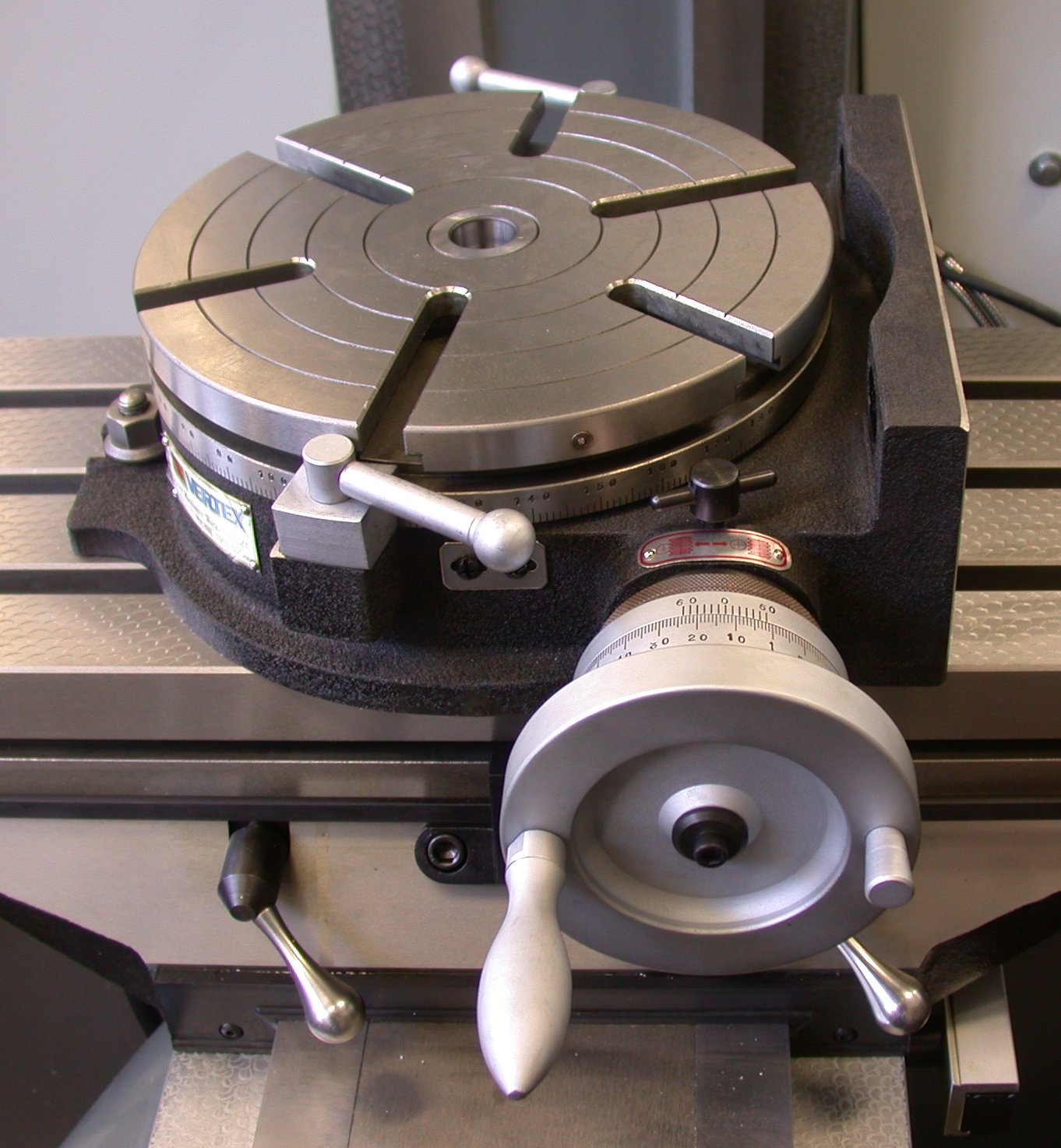
A rotary table is a precision work positioning device used in metalworking. It enables the operator to drill or cut work at exact intervals around a fixed (usually horizontal or vertical) axis. Some rotary tables allow the use of index plates for indexing operations, and some can also be fitted with dividing plates that enable regular work positioning at divisions for which indexing plates are not available. A rotary fixture used in this fashion is more appropriately called a dividing head (indexing head).
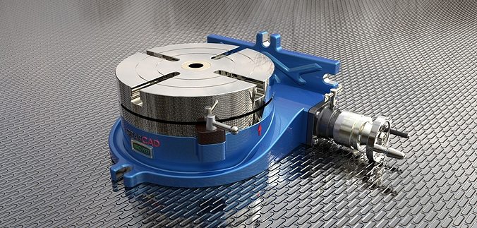
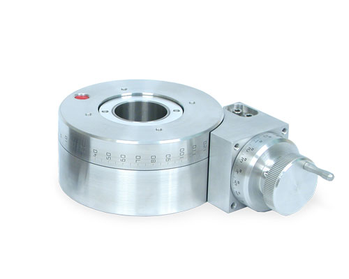
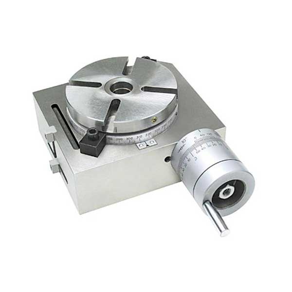
The table shown is a manually operated type. Powered tables under the control of CNC machines are now available, and provide a fourth axis to CNC milling machines. Rotary tables are made with a solid base, which has provision for clamping onto another table or fixture. The actual table is a precision-machined disc to which the work piece is clamped (T slots are generally provided for this purpose). This disc can rotate freely, for indexing, or under the control of a worm (handwheel), with the worm wheel portion being made part of the actual table. High precision tables are driven by backlash compensating duplex worms.
The ratio between worm and table is generally 40:1, 72:1 or 90:1 but may be any ratio that can be easily divided exactly into 360°. This is for ease of use when indexing plates are available. A graduated dial and, often, a vernier scale enable the operator to position the table, and thus the work affixed to it with great accuracy.
Rotary tables are most commonly mounted "flat", with the table rotating around a vertical axis, in the same plane as the cutter of a vertical milling machine. An alternate setup is to mount the rotary table on its end (or mount it "flat" on a 90° angle plate), so that it rotates about a horizontal axis. In this configuration a tailstock can also be used, thus holding the workpiece "between centers."
With the table mounted on a secondary table, the workpiece is accurately centered on the rotary table"s axis, which in turn is centered on the cutting tool"s axis. All three axes are thus coaxial. From this point, the secondary table can be offset in either the X or Y direction to set the cutter the desired distance from the workpiece"s center. This allows concentric machining operations on the workpiece. Placing the workpiece eccentrically a set distance from the center permits more complex curves to be cut. As with other setups on a vertical mill, the milling operation can be either drilling a series of concentric, and possibly equidistant holes, or face or end milling either circular or semicircular shapes and contours.
with the addition of a compound table on top of the rotary table, the user can move the center of rotation to anywhere on the part being cut. This enables an arc to be cut at any place on the part.
Additionally, if converted to stepper motor operation, with a CNC milling machine and a tailstock, a rotary table allows many parts to be made on a mill that otherwise would require a lathe.
Rotary tables have many applications, including being used in the manufacture and inspection process of important elements in aerospace, automation and scientific industries. The use of rotary tables stretches as far as the film and animation industry, being used to obtain accuracy and precision in filming and photography.

This rotary axis is made to order for us by a German precision mechanic. In this price segment, this rotation axis for CNC milling machines is unrivalled in Europe!
There are many rotary tables on the market. If possible, they have to be inexpensive. You can get a lot of them! Usefulness? That is where the wheat is separated from the chaff. For example, there are many CNC turntables with the cheapest belt transmission. The disadvantages are obvious: slippage due to the belt. If not in the belt drive itself, then on the load or idle side of the belt. Perhaps useful for engraving work. For milling, however, usually not or limited in the choice of material (aluminium 3D milling not possible).
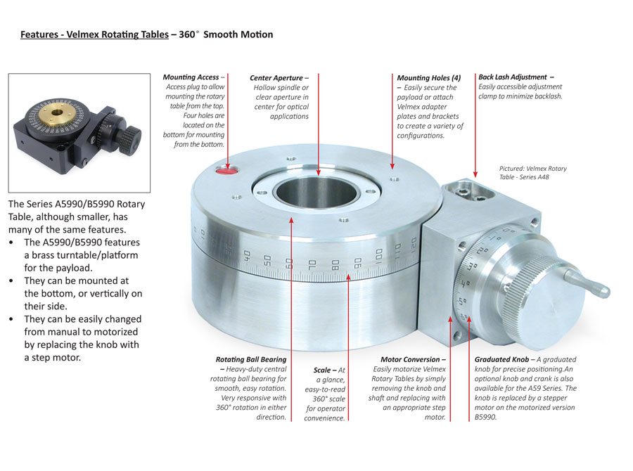
You would use an elevating table when you require free standing vertical travel with a platform shelf. The Velmex Elevating Tables are more rigid then turning a linear stage into a vertical axis, making them more stable. However, if you do want longer travel distance or a narrower or wider frame, almost all Velmex linear stages can be converted to an elevating table with the addition of a base plate and a platform shelf. They can be engineered to provide added rigidity, support and stability.
Velmex Elevating Tables are made of Velmex world renown UniSlide assemblies. They use a deeper base under the dovetail ways for added support and feature an oversize base for added stability in the vertical position. A right angle platform is mounted to the carriage that can be mounted in the inverse to add versatility to the travel envelope.
Yes, UniSlides can be mounted together in XY, XZ, XYZ configurations. Mounting UniSlide assemblies in multi-axis systems requires the use of adapter plates and brackets. They also can be combined with Velmex Rotary Tables and our other linear stages to make custom systems to meet a wide range of applications. See UniSlide Options and Accessories for more information on the plates and adapters. Also see our examples pages for images featuring Elevating Tables combined with other Velmex products.
We launched the SNEED-PACK product line to compliment our comprehensive line of SNEED-JET inkjet coding printers. Many customers are frequently in search of conveyors or material handling solutions to accompany the printer they purchase.
SNEED-PACK Rotary Tables can be used to unscramble product and feed a conveyor, also as a buffer space to accumulate product until the downstream conveyor is ready for additional product or collect. Accumulating rotary tables are designed to collect filled containers from a filling line to prevent slowdowns by quickly removing the finished product from the conveyors during operation. Can be set for clockwise and counterclockwise rotation.
Infeed Table - for easy input of product at the beginning of the conveyor. Alternately, it can be used at the end of the conveyor as a work table for an operator that is pulling and packing finished products.
Infeed Table & Unscrambler - ideal for beginning of the line to feed and unscramble product to input onto the conveyor. Recommended accessory: Transfer Plate & Gate
Simpler operation. Less maintenance. Superior print quality. The all-new Videojet 1510 continuous ink jet printer is engineered to keep your line up and running longer. It’s designed for customers who print multiple shifts per day providing up to 18 months of production before required preventive maintenance. Advanced capabilities • Up to 5 lines of code with speeds up to 914 ft./min. (278.6 m/min.) • Wide range of bar codes (including 2D Data Matrix) • Standard USB and Ethernet Simple to maintain • 9,000-hour core life

Automator rotary dot peen marking systems are made for programmable marking around the circumference or along the axis of round parts by rotating the part in sync with the marking pin. Data entry can be manual or automated for error-free marking with the AC500 touchscreen controller. Automatic date coding, serial numbering, 2D coding are standard features.
Several types of rotary part holding fixtures are available. Each fixture uses a three-jaw, self-centering, adjustable chuck to hold parts of various sizes during marking.
Rotary table are positioning devices used in metalworking, enabling to drill or cut work at exact intervals around a fixed usually horizontal or vertical axis. Rotary tables have many applications, including being used in the manufacturing and inspection process of important elements in machine tools equipment.

We hypothesized that we could produce nano-scale fibers by exploiting a high speed rotating nozzle to form a polymer jet which undergoes extensive stretching before solidification (Figure 1a). Termed rotary jet-spinning (RJS), the RJS system consisted of a reservoir with two side wall orifices that was attached to the shaft of a motor with controllable rotation speed. To facilitate the fiber collection a flexible air foil is placed on the shaft above the reservoir. The polymer solution was continuously fed to the reservoir at a rate sufficient to maintain a constant hydrostatic pressure and continuous flow. The resulting fibers were collected either on a stationary, surrounding cylindrical collector or on coverslips which were held against the collector wall. The fiber production process is composed of (i) jet-initiation to induce flow of the polymer solution through the orifice, (ii) jet-extension to increase surface area of the propelled polymer stream, and (iii) solvent evaporation to solidify and shrink the polymer jet. During the first step (Figure 1b-i), a combination of hydrostatic pressure and centrifugal pressure at the far end of capillary Figure 1b-ii), but the jet travels in a curled trajectory due to rotation-dependent inertia. Stretching of the extruded polymer jet is critical in reducing jet diameter over the distance from the nozzle to the collector. Concurrently, the solvent in the polymer solution evaporates, solidifying and contracting the jet (Figure 1b-iii). The solvent evaporation rate depends on its volatility. If the solvent is highly volatile, the jets form thicker fibers as the rapidly evaporating solvent potentiates rapid solidification, hindering the jet extension. The primary challenges in this process are optimizing the polymer solution properties (viscoelasticity and surface tension), solvent volatility, capillary diameter, and collector radius to not only produce ultra fine fibers but also prevent jet rupture and the formation of droplets due to Plateau-Rayleigh instability We) to Reynolds number (Re), Ca = We / Re, which characterizes the ratio of the viscous force to the surface tension force We = ρU2 D / γ and Re = ρUD / η where ρ, η and γ are density, dynamic viscosity and surface tension of polymer solution, respectively, U is the polymer jet exit speed based on a stationary frame (see Supporting Information for measurement of jet speed) and D is the orifice diameter. A lower capillary number results in shorter jet length and earlier jet break-up to isolated droplets
Schematic of rotary jet-spinning process. (a) Rotary jet-spinning consisted of a perforated reservoir (internal volume of 700 µL and external diameter of 12.5 mm) with two side wall orifices (orifice diameter of 340 µm and length to diameter ratio of 9) which rotates about its vertical axis in the center of a stationary collector; the polymer solution continuously feeds into the reservoir and produces fibers that are deposited over the collector (diameter of 300 mm). (b) Magnified view of the presumed formation mechanism of nano-scale fibers through RJS system, (i) jet-initiation, (ii) jet-extension and (iii) solvent evaporation. (c) Photographic image of 3D nanofiber structures produced by rotary jet-spinning, 8 wt% PLA in CHCl3 at 12,000 rpm rotation speed. (d) Scanning electron micrograph (SEM) of fibers in 1C. (e) PLA fibers (10 wt% PLA in CHCl3 at 12,000 rpm rotation speed) produced with expedited solvent evaporation and high humidity (more than 55% R.H.). (f) SEM of 5 wt% PEO in water spun at 12,000 rpm. (g) SEM of 8 wt% PAA in water at 50% neutralization degree spun at 12,000 rpm, (h) SEM of 8 wt% PAA in water at 100% neutralization degree spun at 12,000 rpm. (i) SEM of 14 wt% gelatin in 20 v/v% acetic acid spun at 12,000 rpm. (j) The laser scanning confocal image of fiber encapsulated fluorescent polystyrene beads (0.2 µm diameter). (k) SEM of emulsion of gelatin in PLA spun at 12,000 rpm rotation speed.
As proof-of-principle, we produced rotary jet-spun fibers from a wide variety of synthetic and naturally occurring polymers. We produced nanofibers from poly (lactic acid) (PLA) in chloroform (Figure 1c–e), poly (ethylene oxide) in water (Figure 1f), poly (acrylic acid) in water at different conductivities (neutralized with sodium hydroxide) (Figure 1g and 1h), gelatin in mild acetic acid (Figure 1i), an emulsion of gelatin in PLA (Figure 1j) and PEO doped with fluorescent spherical beads (Figure 1k) (refer to Supporting Information for more details on sample preparation). These data suggest that RJS is a rapid and facile technique of nanofiber fabrication without electrical propulsion and is capable of fabricating 3D aligned nanofiber structures from a variety of polymers. To study the sensitivity of RJS fiber fabrication to various production variables, we focused on producing PLA fibers (see Table 1 for composition details). As shown in Figure 2, continuous aligned PLA fibers with diameters ranging from 50–3500 nm can be produced. To demonstrate the ability to tailor the nanofiber morphology, we produced nanofibers at different rotation speeds. By increasing the rotation speed from 4,000 to 12,000 rpm, the fiber diameter (median ± median standard error) dropped from 1143 ± 50 to 424 ± 41 nm (Figure 2a–c).
aQ1, Q2 and Q3 are first, second and third quartile of fiber diameter distribution which represent 25th, 50th and 75th percentile, respectively. η0, γ and ρ are shear viscosity, surface tension and density of the solution, U is the jet speed, We, Re and Ca are Weber number, Reynolds number and capillary number, respectively. Orifice geometry for all samples was D=340µm, L:D=9 except for the (*) was D=650µm, L:D=4.5. Fiber diameters can be tailored with the orifice diameters (see Supporting Information for more detail on orifice geometry). These data suggest that by decreasing the length to diameter ratio of the orifice, the pressure drop at the orifice decreases and the rate of solution outflow increases, resulting in larger diameter fibers.
We hypothesize that the mechanism of RJS fiber formation is the optimization of the competing centrifugal forces and jet surface tension. The surface tension causes jet instability and bead formationTable 1 and see Supporting Information for surface tension measurement). The fiber diameter distribution (Figure 2d) is much wider at lower rotation speed and the probability of bead formation is higher. Next, we held the rotation speed constant while varying the polymer concentration in the solvent. We hypothesized that the surface tension of the polymer solution and its tendency to induce beading could be compensated for by varying the polymer concentration. When we held the rotation speed constant, at low polymer concentrations (4 wt%) RJS resulted in polymer beads. As we increased the polymer concentration (c) (4 wt%< c <10 wt%), the increased polymer chain entanglement stabilized the jet resulting in fiber formation. This data demonstrates that fiber formation is a function of the polymer concentration where an optimal range of concentrations increases the likelihood of polymer chain entanglement
We asked how the capillary number (Ca) and polymer solution concentrations affect the quality of fiber production. In this case, we define the highest production quality as bead-free fibers. The Ca number represents the magnitude of the centrifugally-induced shearing forces relative to the surface tension Ca numbers (Figure 3b). As expected, for c
In conclusion, we have developed an effective technique for the generation of continuous fibers and nonwoven fabrics with nanometer size fiber diameters by using high-speed mechanical rotation of polymeric solutions through a perforated rotary reservoir. Rotary jet-spinning has several advantages in comparison with other nanofiber fabrication methods: a) the technique does not require high voltage electric fields, b) the apparatus is simple to implement, c) nanofiber structures can be fabricated into an aligned 3D structure or any arbitrary shape by varying the collector geometry, d) fiber morphology (beaded, textured, or smooth), fiber diameters and web porosity can be manipulated by altering the process variables, e) fiber fabrication is independent of solution conductivity, f) RJS is easily applicable to polymer emulsions and suspensions, and g) RJS is capable of substantially higher production rates as compared to standard electrospinning.

The growing need to machine Ti-based alloys, widely used in almost all branches of industry, to produce components with high quality and precision, leads to the research and development of alternative machining tools. Some kinds of modern materials, including Ti-based alloys, are hard to be machined by conventional methods, due to overheating and quick blunting of tools, its clogging or destruction, which can be caused by high ductility of the machined material, its low thermal conductivity, etc. Therefore, unconventional machining methods can be suitable alternatives, although, given by their flexibility (non-stiffness), their precision can be lower than that of the classical tools.
Despite the fact that many new machining methods, such as laser beams or electro-erosive processes, have been studied, one of the most used and investigated machining tools is the abrasive water jet (AWJ). The research of this tool has been carried on for years and is still ongoing [21,22]. AWJ is a universal tool that has been used for more than 40 years to machine various materials. It has been tested namely for cutting [23], milling [24,25,26,27] and peening [28,29]. However, cutting is the most developed application of AWJ. The main purpose of the majority of published studies was to predict the average depth of cut of the jet, and the final quality of the surface subjected to milling. A thorough description of AWJ machining was performed by Hashish [30,31], who adopted previous models of removing the material in deformation mode (published by Bitter [32,33]), and removing the material in cutting mode (studied by Sheldon and Finnie [34,35]). Later on, some further models based either on a large amount of experimental work [36,37], or on theoretical descriptions of the processes [38,39], were presented. Several statistical models were also presented [40,41,42,43], but their validity on materials studied under experimental conditions is limited, as demonstrated e.g., in [44].
Models of the interactions of AWJ with specimens’ surfaces are of great importance. Some of them consider material parameters, such as Young modulus of elasticity, grain size, material strength and density, while others are based on the previous determination of experimental values. However, most of the models can be used solely for brittle materials [45,46,47], or ductile ones [48,49,50]. The models can only rarely be applied for both the material groups. These are namely the analytical models, e.g., model derived from physical analysis of the process [39]. Nevertheless, the application of such models still requires initial experimental testing to be performed on the investigated material to determine its response to AWJ. Therefore, the analytical models are not commercially used. The description of jet trajectory and its curvature is an essential part of all the used models. Hlaváč [38] defined the curvature of the trajectory within the material through the declination angle. Figure 1 shows a comparison of the declination angle measurement of the two samples with different traverse speed set up. It is clearly visible that with increasing depth of cut, the quality of the wall surface deteriorates. Moreover, the curvature (declination angle) of the jet increases and therefore it is possible to relate the quality of the wall with the declination angle. This phenomenon is a consequence of the decreasing energy of the jet in a material. The declination angle can also be used to determine the parameter of machinability [39]. Based on these facts, information about the machinability of the respective material can be acquired just via performing a single experimental cut unlike complicated calculations via completely theoretical model. Moreover, some of the constants in the theoretical model are hard to determine and it is more time consuming than the above-mentioned semi-experimental method.


 8613371530291