
lcm rotary table free sample

RNase free condition (tools, containers, solutions and handling) should be used in all the following steps of the method from tissue collection, fixation, embedding, LCM through RNA isolation and downstream experiments.
Tissue blocks were trimmed into a desired shape and placed in desired orientation on the plastic embedding rings (Himedia, India). Rings were fixed with the holding clamp of the rotary microtome (Leica RM2265) and 8–10 μm thin tissue sections were made. Tissue sections were flattened for 3–5 mins on water at 50–55 o C (below the melting temperature of paraplast used), taken on HistoBond + charged slides (Marienfeld, Germany), dried for maximum 30 mins on hot plate at 42 °C and stored temporarily at 4 °C until LCM was performed. Since the incubation temperature of tissues may affect RNA quality
Tissue sections were dewaxed by dipping the slides twice in histoclear (Histochoice clearing reagent, Sigma Aldrich, USA) for 2 mins and air dried at RT. Initial observation of the tissues were done under stereo microscope. Slides were observed under LCM microscope, embryos were identified, RAMs were marked using on screen tool of PALM MicroBeam (Carl Zeiss, Germany). Tissues were laser cut along the marking and followed by catapulting. LCM-based catapulted tissues were collected in RNase free 0.5 ml tubes having a drop of mineral oil (Amresco,USA) and stored temporarily at –80 °C or directly used for RNA isolation.
Collection tubes containing LCM-derived tissues were centrifuged at 5000 rpm for 1 min, 150 μl of TRI-reagent (Sigma Aldrich, USA) was added and centrifuged at 5000 rpm for another 2 mins. 100 μl of chloroform (Qualigen, USA) was added to the tube and followed by brief vortexing, incubation at RT for 15 minutes and centrifugation at 13000 rpm for 30 mins. The upper aqueous phase was taken into a fresh 1.5 ml microfuge tube (Axygen, India); equal volume of isopropanol (Qualigen,USA) was added, mixed and kept at −20 °C for 1 hr and followed by centrifugation at 13,000 rpm for 1 hr. The supernatant was discarded and the pellet was washed with 100 μl of 70% ethanol by centrifuging at 7500 rpm for 15 mins. The pellet was air dried and finally dissolved in 10 μl of nuclease free water (Sigma). The concentration and RIN of the RNA samples were checked using Nanodrop 1000 (Thermo Fischer Scientific, USA) and Bioanalyzer nanochip (Agilent, 2100), respectively.
This paper presents the successful field testing of a modified measurements while drilling (MWD) tool to handle high concentrations of lost circulation material (LCM) in the mud system. This specially formulated high concentration LCM mud system is commonly used to enable drilling through severely depleted and unconsolidated sandstone reservoirs without lost circulation. In this application the MWD tool is used to provide real time directional surveys, formation evaluation and drilling efficiency data.
The original design of the MWD tool limited its use with this LCM mud system because of the tool"s high susceptibility to plugging. Research and development by the MWD company in cooperation with the Operator led to modifications of the MWD tool which now enables it to handle very high LCM concentrations without plugging, resulting in considerable cost savings to the Operator. The MWD company has also benefitted by extending their tool"s application to a harsh LCM environment.
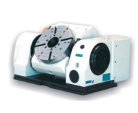
4 THE TRANSMIS SION W orm-gear system Optimal rigidity and higher precision The Worm-screw Using a worm-screw made of cemented and hardened steel having a unique precision ground profile that guarantees a wide contact sur face. L.C.M. The Crown Constructed from bronal, this self - lubricating alloy allows a preload to be applied to all LCM tables for increased dynamic accuracy and no backlash.
5 Torque motor High speed, zero backlash L.C.M. L.C.M. L.C.M. L.C.M. produces a wide range of tables with torque motors. This technology allows LCM to build tables with similar working torque to the worm/gear system, but with higher rotational speeds. Another important advantage is the zero backlash providing high dynamic response and accuracy thanks to rapid bi-directional response. Liquid cooling increases torque and reduces thermal expansion. Equipped with a directly mounted rotary encoder, these tables provide extremely precise position accuracy.
6 ELEMENTS OF CONSTRUCTION Fully sealed sumps (covers) thanks to O-ring seals. F orced pressurisation system.. The table is made from a special alloy having high mechanical strength and features higher than steel or cast iron. Table load is reduced resulting in less wear and thermal expansion of machine tool ballscrews Crossed rollers bearings Cemented and hardened disk
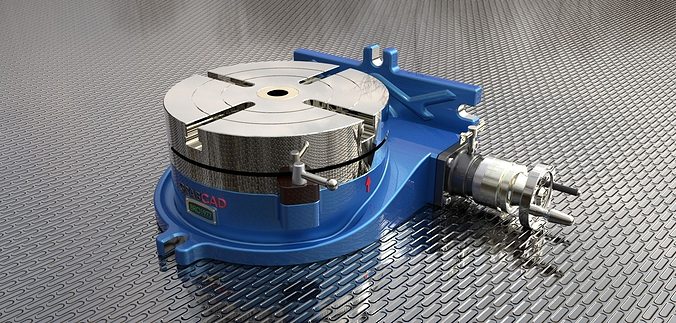
8 Index CNC Rotary tables Vertical-horizontal positioning Mechanical transmission - Pneumatic clamping CNC Rotary tables with manual tilting Tilting axis positioning by handweel Mechanical transmission - Rotary axis pneumatic clamping CNC Tilting rotary tables Mechanical transmission P neumatic clamping TDE P. 10 BAS-V P. 12 BSC P. 14 Mechanical transmission tables CNC multispindle tilting tables Simultaneous control of multiple rotating spindles Mechanical transmission - Pneumatic clamping MTX P. 16 CNC rotary tables Horizontal positioning on machine table Mechanical transmission - Hydraulic clamping CNC Tilting tables Designed and made for 5 axis machines Mechanical transmission - Hydraulic clamping TDE-M TRB-M P. 18 BRC-MM P. 20 CNC Tilting tables Designed and made for 5 axis machines Mechanical transmission - Hydraulic clamping BRS-MM P. 22 8
9 - CNC Tilting rotar y tables Designed and made for 5 axis machines T orque motor - Hydraulic clamping - CNC rotary tables Horizontal positioning on machine table Torque motor - Hydraulic clamping CNC rotary tables Horizontal positioning inside the machine table Torque motor - Hydraulic clamping - CNC Tilting rotar y tables Designed and made for 5 axis machines Torque motor - Hydraulic clamping Tilting heads for milling Mechanical transmission Hydraulic clamping BRS-TT P. 23 TDE-T P. 24 TRB-T P. 26 BRC-T P. 28 MD-M P. P Torque Motor tables Tilting heads for milling Index Tilting heads for milling T orque motor Hydraulic clamping MD-T P. 36 EDM CNC rotary tables for EDM machines Mechanical transmission TDL -BSL P. 38 EDM Rotary tables for EDM 9
10 TDE CNC Rotary tables Vertical-horizontal positioning Mechanical transmission Pneumatic clamping - Specifications - Models TDE 125 TDE 200 TDE 250 TDE 350 Table diameter (398 Opt.) Center bore Center height T Table T -slots width Clamp system Pneumatic Pneumatic Pneumatic Pneumatic Clamp torque Nm / Worm screw/wheel ratio 1/90 1/60 1/60 1/60 / Worm screw/motor ratio 1/2 1/2 1/2 1/2 47 Servo motor size (page 47) Max rotation speed Rpm 16, Indexing accuracy sec. ±15 ±15 ±15 ±15 Minimum increase Max allowable load vertical Max allowable load horizontal Max allowable thrust vertical Max allowable thrust horizontal FxL Nm N Working torque Nm Table net weight
12 BAS-V CNC Rotary tables with manual tilting Tilting axis positioning by handweel Mechanical transmission Rotary axis pneumatic clamping Tillting axis manual mechanical clamping - Specifications - Models BAS-V125 BAS-V200 BAS-V250 BAS-V320 Table diameter Center bore Center height T Table T-slots width Tilt range Axis Rotary Tilting Rotary Tilting Rotary Tilting R otary Tilting Clamp system Pneumatic Manual Pneumatic Manual Pneumatic Manual Pneumatic Manual Clamp torque Nm / Worm screw/wheel ratio 1/ / / / Servo motor size (page 47) Max rotation speed Rpm 16, , , ,6 --- Indexing accuracy sec. ±15 ±30 ±15 ± 30 ±15 ±30 ± 15 ± 30 Minimum increase N Working torque FxL Nm Nm Table net weight
14 BSC CNC Tilting rotary tables Mechanical transmission Pneumatic clamping - Specifications - Models BSC 125 BSC 200 BSC 250 BSC 320 Table diameter Center bore Center height T Table T-slots width Tilt range Axis Rotary Tilting Rotary Tilting Rotary Tilting Rotary Tilting Clamp system Pneumatic Pneumatic Pneumatic Pneumatic Pneumatic Pneumatic Pneumatic Pneumatic Clamp torque Nm / Worm screw/wheel ratio 1/180 1/180 1/180 1/120 1/180 1/180 1/180 1/ Servo motor size (page 47) Max rotation speed Rpm 16,6 16,6 16, ,6 16,6 16,6 12,5 Indexing accuracy sec. ±15 ± 30 ± 15 ±30 ±15 ± 30 ±15 ± 30 Minimum increase N Working torque FxL Nm Nm Table net weight
16 MTX 125 CNC multispindle rotary tilting tables Simultaneous control of multiple rotating spindles Mechanical transmission Pneumatic clamping - Specifications - Models MTX MTX Table diameter Center bore Center height T Table T -slots width 6 6 Tilt range Axis Clamp system Rotary Tilting Rotary Tilting Pneumatic Pneumatic Pneumatic Pneumatic Clamp torque Nm / Worm screw/wheel ratio 1/234 1/180 1/234 1/ Servo motor size (page 47) Max rotation speed Rpm 12,8 16,6 12,8 16,6 Indexing accuracy sec. ± 30 ±30 ± 30 ± 30 Minimum increase N FxL Nm Working torque Nm Table net weight
18 TDE-M / TRB-M CNC Rotary tables Horizontal positioning on machine table Mechanical transmission Hydraulic clamping - Specifications - Models TRB-M 550 TDE-M 500 TDE-M 600 TDE-M 0 Table diameter Table T-slots width Clamp torque (entry pressure) Nm (40 Bar) 1500 (40 Bar) 3300 (40 Bar) (20 Bar) 47 Servo motor size (page 47) Speed reduction ratio 1/154 1/90 1/90 1/120 Max rotation speed Rpm 12,8 33,3 33,3 25 Indexing accuracy sec. ±10 ±10 ±10 ±10 Max allowable load horiz. Kg Max allowable thrust horiz. N Working torque Nm Table net weight TRB-M TRB-M TDE-M -±5" 2.5" The TRB-M table series are designed for complete integration to the machine tool bench. This solution allows full use of milling table surface without restriction. The TRB-M e TDE-M table series can be equipped with: - Positioning encoder mounted in axis with ±5" or ±2,5" accuracy. - Customized table surface with various T-slots, smooth plate, or threaded holes. - Painted to specific RAL colour - Modified motor cover 18
20 BRC-MM CNC Tilting rotary tables - Designed and made for 5 axis machines Mechanical transmission - Hydraulic clamping - Specifications - Models BRC-MM 200 (250) BRC-MM 350 (400) BRC-MM 500 BRC-MM 600 Table diameter 200 (Opt. 250) 350 (Opt 400) Max diameter of workpiece Table T-slots width Tilt range Axis Clamp system Rotary Tilting Rotary Tilting Rotary Tilting Rotary Tilting Pneumatic Pneumatic Pneumatic Pneumatic Hydraulic Hydraulic Hydraulic Hydraulic Clamp torque (entry pressure) Nm. 400 (6 Bar) 0 (6 Bar) 0 (6 Bar) 1600 (6 Bar) 1200 (60 Bar) 2800 (60 Bar) 2200 (40 Bar) 3000 (40 Bar) / Axis/motor ratio 47 Servo motor size (page 47) 1/120 1/120 1/120 1/120 1/120 1/180 1/180 1/ Max rotation speed Rpm ,6 16,6 16,6 Indexing accuracy* Working torque 0 sec. Nm ±10 ±30 ±10 ±30 ±10 ±30 ±10 ± Table net weight N. FxL Nm *BRC-MM2.5 * The BRC-MM table series are prepared for installation of high resolution encoders (up to±2,5 ) on both axis. They can also be equipped with hydraulic/pneumatic distributor for the control of any workholding equipment installed on the table surface. 20
22 BRS-MM CNC Tilting rotary tables - Designed and made for 5 axis machines Mechanical transmission - Hydraulic clamping Specifications BRS MM 500 Specifications Axis Rotary Tilting Table Dimensions 500 x 500 Clamp system Hydraulic Hydraulic Max diameter of workpiece 600 Clamp torque at 50 Bar Nm T Table T-slots width 14 (47 ) Servo motor size (page 47) 4 5 Tilt range ± Max rotation speed Rpm Max allowable load 250 * Indexing accuracy* sec. ± 15 ± 30 Table net weight 750 Working torque Nm *BRC-MM2.5 * The BRS-MM table series are prepared for installation of high resolution encoders (up to± 2,5 ) on both axis. They can also be equipped with hydraulic/pneumatic distributor for the control of any workholding equipment installed on the table sur face. Mechanical transmission BRS-MM
23 L C M BRS-TT Torque motor CNC tilting rotary table Designed and made for 5 axis machines Torque motors Hydraulic clamping Specifications BRS TT 600 Specifications Axis Rotary Tilting Table Dimensions 600 Clamp system Hydraulic Hydraulic Max diameter of workpiece 700 Clamp torque at 40 Bar Nm T Table T-slots width 14 Nominal torque S1 Nm Tilt range ± Peak torque S6-5% Nm Max allowable load 250 Max rotation speed Rpm 50 Table net weight 980 Indexing accuracy* sec. ±5 ±5 BRC-MM±2,5 ) * The BRS-MM table series are prepared for installation of high resolution encoders (up to ±2,5 ) on both axis. They can also be equipped with hydraulic/pneumatic distributor for the control of any workholding equipment installed on the table sur face. Torque Motor tables BRS- TT
24 TDE- T CNC Rotary tables with torque motor Torque motor Hydraulic clamping TDE-T - - The TDE-T table series can be supplied with: - Customized table surface with various T-slots, smooth plateor threaded holes. - Painted to specific RAL colour - Specifications - Models TDE -TV 270 TDE - TV 400 TDE -TH 450 TDE -TH 600 TDE-TH 800 (0) Table diameter (Opt.0) Center bore 75 X L= X L= X L=30 50 X L=30 60 X L=30 Center height ///// ///// ///// T Table T-slots width Clamp system Hydraulic Hydraulic Hydraulic Hydraulic Hydraulic Clamp torque (entry pressure) Nm. 855 (50 Bar) 1960 (50 Bar) 1800 (50 Bar) 3000 (40 Bar) 5000 (40 Bar) (S1) Continuous torque (S1) Nm (S6) Peak torque (S6) Nm Max rotation speed Rpm Indexing accuracy sec. ±5 ±5 ±5 ±5 ±5 Max allowable load Kgf ///// ///// ///// Max allowable thrust F x L Nm Max allowable load horizontal Kgf ///// ///// Max allowable thrust horizontal N ///// ///// Table net weight
25 TDE-T CNC Rotary tables with torque motor Torque Motor tables TDE-TV 270 Torque motor Hydraulic clamping TDE-TV 400 TDE-TH 450 TDE-TH 600 TDE-TH 800 (0) 25
26 TRB-T CNC Rotary tables with torque motor - Horizontal positioning inside the machine table Torque motor - Hydraulic clamping TRB-T TRB-T - - The TRB-T table series are designed for complete integration to the machine tool bench. This solution allows full use of milling table sur face without restriction. TRB-T table series can be supplied with: - Customized table sur face with various T-slots, smooth plate, or threaded holes. - Painted to specific RAL colour - Specifications - Models TRB - T 400 TRB - T 600 TRB - T 800 Table diameter Table T -slots width Clamp system Hydraulic Hydraulic Hydraulic Clamp torque (entry pressure) Nm (60 Bar) 2500 (50 Bar) 5900 (40 Bar) (S1) Continuous torque (S1) Nm (S6) Peak torque (S6) Nm Max rotation speed Rpm Indexing accuracy sec. ±5 ±5 ±5 Max allowable load horizontal Kg Max allowable thrust horizontal N Table net weight
27 TRB-T CNC Rotary tables with torque motor Horizontal positioning inside the machine table Torque motor - Hydraulic clamping Torque Motor tables TRB-T 400 TRB-T 600 TRB-T
28 BRC-TM / BRC-TT Torque tilting rotar y table Designed and made for 5 axis machines Torque motor Hydraulic clamping - Specifications - Models BRC-TM 400 BRC-TT 600 Table diameter Max diameter of workpiece T Table T -slot width Tilt range Axis Clamp system Rotary Tilting Rotary Tilting Hydraulic Hydraulic Hydraulic Hydraulic Clamp torque Nm (60 Bar) 3 (60 Bar) 2500 (40 Bar) 4500 (40 Bar) / Axis/motor ratio 1/1 1/180 1/1 1/1 47 Servo motor size (page 47) 5 Torque Torque Torque Max rotation speed Rpm 90 16, * Indexing accuracy sec. ± 5 ± 25 ± 5 ±5 Working torque Nm 393 (S1) (S1) 1600 (S1) N Table net weight FxL Nm *BRC-MM±2,5 *The BRC-TM / BRC-TT table series are prepared for installation of high resolution encoders (up to ±2,5 ) on both axis They can also be equipped with hydraulic/pneumatic distributor for the control of any workholding equipment installed on the table sur face. 28
29 BRC-TM/BRC-TT Torque tilting rotary table Torque Motor tables BRC- TM 400 Designed and made for 5 axis machines Torque motors Hydraulic clamping BRC- TT
31 MD-M Tilting heads for milling Choice of head depending on machine geometry Type of head Machine geometry Units complete with robotic flexible cable chain. Fitted as standard allowing free rotation of cables and feed pipes. I 11 Unit complete with up to 11 utilities rotary union.this version to be adopted in cases of limited installation depth C 31
32 MD-M Tilting heads for milling Mechanical transmission Hydraulic clamping Choice of spindle configuration Specifications Type of head MD MD prepared for square electrospindle S MD MD complete of case suitable for the fixing of cartridge electrospindle C L.C.M. MD complete with L.C.M. electrospindle E 32
37 ELQ MD Electrospindle for MD heads L.C.M. () MD L.C.M electrospindles (built -in motors) are designed specifically for use with the MD series tilting head. The structure and all components have been designed to work reliably in both vertical and horizontal positions. The spindle mounting and utility connection system eliminates the need for additional housing and inter face connections. Using the high strength alloy structure it guarantees a good weight / rigidity ratio. Low temperature and minimal thermal expansion is assured with ceramic bearings and liquid cooling. A directly mounted encoder is fitted to allow rigid tapping and spindle orientation.. The motor cooling is by liquid and tool unclamp is hydraulic. Max speed S1 * S6 * Model Lubrication Taper Power Torque S1 * Torque S6 * Air oil Grease ELQ ELQ ELQ ELQ ELQ HSK A50 ISO 30 HSK 63 ISO 40 ELQ HSK 63 ISO 40 ELQ HSK 63 ISO 40 HSK 63 ISO 40 HSK 80 ISO 40 HSK A ISO KW 18 Nm 28 Nm 21 KW 67 Nm 103 Nm 24 KW 78 Nm 120 Nm 33 KW 105 Nm 162 Nm 38 KW 125 Nm 193 Nm 38 KW 166 Nm 234 Nm 38 KW 166 Nm 234 Nm Suitable for heads MD M 90 MD M 125 MD M 125 MD M 160 MD T 360 MD M 160 MD T 360 MD M 160 MD T 360 MD M 160 MD M 200 MD M 160 MD M 200 * RPM 37
38 TDL 200 EDM CNC rotary tables for EDM machines Mechanical transmission - Specifications - Models TDL 200 Table diameter 200 Worm screw/wheel ratio 1/60 / Worm screw/motor ratio 1/2 47 Servo motor size (page 47) 2 Max rotation speed Rpm 25 Indexing accuracy Minimum increase Max allowable load vertical Max allowable load horizontal Protection Table net weight sec. ±15 0, IP68 50 ±2,5sec. LCM WNC50 1AX NC Tables suitable to be used on EDM machines for machining operations completely immersed in dielectric fluid. Most important features: Structure fully made of antioxydant materials (stainless steel and alloy) Indexing accuracy up to ±2,5 sec. by in-axis encoder Low tension digital brushless motors Fully sealed sump thanks to o-ring seals Suitable for fixing the most important chucks for pallets Possibility to be controlled by LCM WNC 50 1AX NC TDL 200 Rotary tables for EDM 38
39 BSL 125 EDM CNC rotary tilting tables for EDM machines Mechanical transmission Specifications Table diameter Center height Tilt range BSL Axis Rotary Tilting / Worm screw/wheel ratio Max rotation speed Indexing accuracy with direct encoder Minimum increase 0 Protection Table net weight Rpm 1/180 1/180 16,6 16,6 ±5 ±5 40 IP 68 55, ±2,5 sec O LCM WNC 50 2AX NC Tables suitable to be used on EDM machines for machining operations completely immersed in dielectric fluid. Most important features: Structure fully made of antioxydant materials (stainless steel and alloy) Indexing accuracy up to ±2,5 sec. by in-axis encoder Low tension digital brushless motors Fully sealed sump thanks to o-ring seals Suitable for fixing the most important chucks for pallets Possibility to be controlled by LCM WNC 50 2 AX NC BSL 125 Rotary tables for EDM 39
40 Accessories Tailstocks Manual tailstocks CP3V - CP4V - Models-Specifications Morse Taper H C L P F B D CP3V CP3V127 CP3V CP3V CP3V CP3V CP4V CP4V CP4V215 CP4V Pneumatic tailstocks CP3P - CP4P - Models-Specifications Morse Taper H C L P F B D CP3P CP3P151 CP3P CP3P CP3P CP4P CP4P180 CP4P215 CP4P Tilting base for tailstock RB3 - RB4 Base useful to tilt the tailstock to one side maintaining the alignment with the table. Available for all versions of tailstocks. RB3 CP3_ RB4 CP4_ RB3 Tilting base for tailstocks model CP3_ RB4 Tilting base for tailstocks model CP4_ 40
42 D B A M Accessories - Workholding Manual systems AMT Manual self-centering chuck ISO40/50 Tie-rod for ISO 40/50 tapers Chuck for pallet FCM ISO40/50 Manual systems for ISO 40/50 tapers Automatic systems CLP Pneumatic cylinder CLI Hydraulic cylinder / RT2 Hydraulic/pneumatic r Manual 3 jaw chucks otary union with 2 passages - Models-Specifications AIT Automatic 3 jaw chucks APT AHT Pneumatic self-centering chuck Hydraulic self-centering chuck Chuck for pallet BT40 FCA Automatic system for BT40 tapers AMT D D1 A B C E H M Weight D1 AMT AMT AMT xM8 3xM8 3xM10 2.8Kg 4.8Kg 8.5Kg AMT xM10 16Kg AMT xM12 26Kg C H E AMT xM12 43Kg Automatic 3 jaw chucks with pneumatic cylinder APT - Models-Specifications (6Bar) Gripping force (6 Bar) For tables size D A L APT KN APT KN 320 / Automatic 3 jaw chucks with hydraulic cylinder AHT - Models-Specifications (25Bar) Gripping force (25 Bar) For tables size D A L AHT KN AHT KN 320 /
43 Automatic 3 jaw chucks Accessories-Workholding AIT - Models-Specifications Suitable for tables size Suitable cylinder D d L AIT CLP250-2 / CLI AIT CLP320-2 / CLI TDE AIT CLP250-2 Pneumatic cylinder CLP - Models-Specifications 6Bar Traction force (6 Bar) For tables size D d C L CLP N CLP N CLP N CLP N CLP N Hydraulic cylinder CLI - Models-Specifications For tables size D d C L H A CLI M22x1,5 25 //// M44x1,5 CLI M22x1, M75x1,5 CLI M22x1, M85x2 80Bar15878N Traction force at 80 bar is N Hydraulic/pneumatic rotary union with 2 ways RT2 - Models-Specifications Max pressure For tables size d D L A RT Bar 125 M30x1, RT Bar 200 M44x1, RT Bar 250 M75x1, RT Bar 320 M85x
44 Accessories - Workholding ISO40/50 Manual systems for ISO 40/50 tapers FCM - Models-Specifications Type of taper Suitable for tables size FCM40I200 ISO FCM40I250 ISO FCM50I200 ISO FCM50I250 ISO ISO/HSK Automatic systems for ISO / HSK tapers FCA - Models-Specifications Type of taper Suitable for tables size FCA40I200 ISO FCA40I250 ISO FCA50I200 ISO FCA50I250 ISO FCA63H250 HSK A ISO40/ N Clamping force N Working hydraulic pressure (necessary for unhook) Available different types of pull-stud BSC FCA ISO 40 Pallet systems RT2 39 The tables can be prepared for the integration of the more common pallets fixing systems. Using the RT2 rotary unions (page 39) it is possible to automatically control the pallets hooking/unhooking. BSC Erowa BSC System 3R 44
45 - Accessories-Encoder L.C.M. All L.C.M. Tables are preset for mounting a high resolution encoder, direct on axis (both rotary and tilting axis). High resolution encoder EDR Models of tables Accuracy after laser compensation Type of encoder TDE 125 / 200 / 250 / 350 BASV 125 / 200 / 250 / 320 BSC 125 / 200 / 250 / 320 ±5 EDR High resolution encoder EDC Models of tables Accuracy Type of encoder TDE M 500 / 600 / 0 - TRB M 550 BRC MM 200 / 350 / 500 / 600 BRS MM 500-BRS TT 600-BRC TM 400-BRC TT 600 TDETV 270 / TDETH 450 / 600 / 800 TRBT 400 / 600 / BSL 125 ±5 EDC50 ±2,5 EDC25 Technical informations about indexing accuracy Conversion of angle seconds to arc length in μm D S L L= μm Arc length in μm S= Angle seconds D= mm Diameter of the circumference in mm. 400 D mm Ø Diameter D in mm Example L= ±5 S x D 413 (μm) μm Arc length in μm 45
46 WNC 50 Numerical control for tables WNC50L.C.M. WNC50 start M-code RS232 USB The WNC 50 is a numerical control providing complete programming and motion control of all LCM tables,both 1 and 2 axes,with mechanical transmission.it is supplied complete with a practical operator interface with data wireless transmission, membrane keypad and back lighted alphanumeric LCD display.during programming operations,the presence of no cables allows the operator to move with the console in his hands programmed.its use is facilitated thanks to several functions specific for rotary axes.programs can be run directly from the machine tool by M-code or manually by pressing the start key.program data can easily be loaded and downloaded via RS232 interface or by USB port. - Specifications-Models WNC 50 1AX WNC 50 2AX Number of axes 1 2 Visualisation Keypad Maximum quantity of programs in memory Maximum quantity of blocks for every program Max transmission distance Voltage Air entry pressure LCD LCD backlighted 16 Sealed membrane,16 key V - 50 Hz 6 Bar LCD LCD backlighted 16 Sealed membrane, 16 key V - 50 Hz 6 Bar CONNECTION DIAGRAM 220 M 46
47 SUITABLE SERVO MOTORS L.C.M. CNC L.C.M.CNC L.C.M. tables and heads are prepared to install motors from all popular CNC brands. The table below shows suggested motors divided by size group and brand. For each LCM product the requird motor can be selected by the suggested size and appropriate brand for the CNC of the machine tool. Size Fanuc Beta is Alpha i Alpha Alpha i Alpha is Alpha HVis Beta is Alpha i Alpha is Alpha HVis Beta is Alpha is Alpha HVis Beta is Alpha is Alpha HVis Beta is Alpha Alpha Alpha i Alpha is Alpha HVis Beta is Alpha is Alpha HVis Beta is Alpha is Alpha HVis Beta is Alpha Alpha HVis Beta is Siemens //// 1FK71015AF711AG0 1FK70337AK711AG0 1FK70425AF711AG0 1FK70635AF711AG0 1FK70835AF711AG0 1FK71055AC711AG0 1FT61058AF714AG0 Yaskawa SGMAH-04AAA2S SGMAH-08AAAS SGMAH-08AAAS SGMGH-09-ACA2S SGMGH-13-ACA2S SGMGH-20-ACA2S SGMGH-40-ACA2S SGMGH-30-ACA2S SGMGH-50-ACA2S Mitsubishi HC-MF S 23 HC-MF S 43 HC-KFS 23 HC-KFS 43 HA23N HC-KFS43 HC-KFS73 HC-MFS73 HA33N HC-KFS73 HC-MF S73 HC-RFS103 HC-RFS153 HC-RFS203 HC202 HF104T HF154T HC-SFS152 HC-RFS153 HC-RFS203 HC-RFS353 HF354S HC-SFS352 HC-RFS353 HC-RFS503 HC-SFS352 HC-SFS502 HC-RFS503 Panasonic PMSMD042P1C PMSMD082P1C PMSMD082P1C PMHMA152P1G PMHMA302P1C PMHMA402P1C Heidenhain //// //// 1FK7042-5AF71 cod QSY130C ECODYN QSY130E ECODYN 1FK7063-5AF71 cod QSY155C QSY155C ECODYN QSY155B QSY155D QSY155B ECODYN QSY155D ECODYN QSY155F QSY155FECODYN L.C.M. Other models of motors can be used. Please,contact L.C.M.for the complete list or tell us specifications and dimensions. 47
52 LCM Precision Technology S.r.l. Head Office: Via Statale, 25/k Castell"Alfero (AT) - Italy Registered Office: Viale Andrea Doria, 48/A Milano - Italy Tel. (+39) Fax (+39) lcm@lcmitalia.it - Web site: CIN-ENG

Our direct drive rotary tables provide high torque and are easy to integrate. They contain high-energy magnets in a simplified mechanical design and drive loads directly without the need for a transmission mechanism or gearbox. It allows customers to build them right into a drive system for flexible placement and integration with cooling pipes and cables, for example.
We supply a wide range of frameless motors, and our adjustable motors include an optical encoder, scale, bearing and housing. Given our selection, it can be challenging to choose the best direct drive motor for your project. Our engineers prefer to help you find the right rotary table for your requirements.
Our most popular rotary motor, the AXD series is characterized by a slim, compact "pancake" design with high peak and continuous torque despite the motor"s quite small form factor.Direct drive and brushless motor
The ACD series is a set of ironless rotary tables. This motor is cogging-free and features high-resolution optical encoder feedback and low speed variability. This permanent magnet motor is equally suited for either low or high speed applications.Zero cogging coreless motor
[0003] Different types of "lost circulation materials" (hereinafter "LCM") may be used . These include cellulose and chitin. Cellulose is the world"s most abundant biopolymer on earth. It is natural, renewable, and biodegradable. It is synthesized by plants as well as by some specialized bacteria . Its molecular structure is constituted by a linear backbone of β-l, 4-O-glycosyl linked D-
[0011] The present invention generally relates to the use of LCMs in subterranean operations, and, more specifically, to the use of nano- carbohydrate composites in wellbore fluids as LCMs during subterranean operations.
[0012] A novel use of nano-carbohydrate LCMs is to utilize materials in a sheet form that may be folded, rolled, shredded, torn or cut into useful shapes for use in downhole applications.
[0014] A further novel use of nano-carbohydrate LCMs is to provide sack materials for products that can be shredded at the rig site and used directly as LCMs downhole.
[0015] Several advantages the nano-carbohydrate based sheets offer are strengths and Young"s moduli that were unobtainable in the past. Additionally, the nano-carbohydrate based sheets may be made with materials that can be removed with acids, enzymes, etc. In some embodiments, they may provide suspension and or prevent sag. Further, the LCMs outlined in this disclosure may be sourced from waste material. In some embodiments, to manufacture them, they require only simple processing and are chemically nontoxic.
[0016] As illustrated in Fig. 1, one embodiment 10 of the present invention utilizes nano-carbohydrate based sheets 11 that have been folded into a flat "origami" type of structure 13. This compact configuration allows the folded sheet to be pumped downhole at a fraction of the original cross-sectional area, thereby delivering a concentrated LCM to a targeted portion of the wellbore without altering the rheological properties of the carrier fluid as a powder may alter it. In several embodiments, the folded flat configuration may be achieved by folding the sheet in half at least one time. In one embodiment, a square shaped nano-carbohydrate based sheet 11 is folded in half twice 12, thereby reducing its cross-sectional area by 75%. In another embodiment, the sheet 12 is further folded in half two more times 13, thereby reducing its cross- sectional area to 1/16 of the original cross-sectional area 14. In certain embodiments, any shape of nano-carbohydrate based sheet may be folded at least once to reduce the cross-sectional area . The fold may be in half, or may be any fold that reduces the cross-sectional area of the sheet.
some embodiments, the chemicals may be solids or liquids. In certain embodiments, the case of solids, a pouch or container constructed of nano- carbohydrate based sheets may be used without an additional coating on the solid materials. Exemplary but not limiting examples of the shapes of the containers are spherical, ovoid, square, rectangular, triangular, circular, or cylindrical . In the case of liquids, an additional encapsulating material may be necessary, thereby forming a capsule with a membrane as its outer surface. Isolation of the encapsulated material from the carrier fluid and the downhole environment by the nano-carbohydrate based sheet containers provides several advantages. For example, using encapsulated well treatment chemicals permits blending of normally incompatible compounds in the carrier fluid. As an example, the present invention permits the transport of an acid compound to a downhole environment by a carrier fluid having a neutral or basic pH without detrimentally impacting either the carrier fluid or the acid. Even though the acid may be in a separate capsule, the nano-carbohydrate based sheet containers may provide extra protection for the capsule on its way to the downhole treatment site. A non-limiting list of mechanisms suitable for releasing the encapsulated fluid includes : a change in pH, crushing, rupture, dissolution of the membrane, diffusion and/or thermal melting of the encapsulating membrane. Following placement of the liquids downhole, the liquids are then released from the capsules and allowed to react. A non-exclusive list of common well treatment chemicals and additives includes: acid etching agents, scale inhibitors, corrosion inhibitors, biocides, paraffin and asphaltene inhibitors, H2S scavengers, oxygen scavengers, demulsifiers, clay stabilizers; surfactants, acidizing agents and mixtures thereof. The controlled downhole release of these chemicals will significantly improve their functionality.
be shredded into, or by, the mixing hopper. The bentonite may act a viscosifier, and the nano-carbohydrate based sheet bag would act as a LCM additive.
[0026] Every fluid inherently has at least a continuous phase. A fluid can have more than one phase. The continuous phase of a well fluid is a liquid under standard laboratory conditions. For example, a well fluid can in the form of be a suspension (solid particles dispersed in a liquid phase), an emulsion (liquid particles dispersed in another liquid phase), or a foam (a gas phase dispersed in liquid phase). As used herein, a "water-based" means that water or an aqueous solution is the continuous phase of the substance. In contrast, "oil- based" means that oil is the continuous phase of the substance. In this context, the oil of an oil-based fluid can be any oil . In general, an oil is any substance that is liquid standard laboratory conditions, is hydrophobic, and soluble in organic solvents. Oils have a high carbon and hydrogen content and are relatively non-polar substances, for example, having a polarity of 3 or less on the Synder polarity index. This general definition includes classes such as petrochemical oils, vegetable oils, and many organic solvents. All oils can be traced back to organic sources.
[0027] In several embodiments, an aqueous carrier fluid may be used . The aqueous carrier fluid of the present embodiments can generally be from any source, provided that the fluids do not contain components that might adversely affect the stability and/or performance of the treatment fluids of the present invention. In various embodiments, the aqueous carrier fluid can comprise fresh water, acidified water, salt water, seawater, brine, or an aqueous salt solution. In some embodiments, the aqueous carrier fluid can comprise a monovalent brine or a divalent brine. Suitable monovalent brines can include, for example, sodium chloride brines, sodium bromide brines, potassium chloride brines, potassium bromide brines, and the like. Suitable divalent brines can include, for example, magnesium chloride brines, calcium chloride brines, calcium bromide brines, and the like.
[0040] Cross-linked chitin nanocrystal derivatives are hydrocarbon chitin nanocrystal derivatives that have been coupled or cross-linked such that the nanocrystals are coupled by the hydrocarbon functional group. For forming cross-linked hydrocarbon chitin nanocrystal derivatives where the hydrogen functional group is a carboxyl functional group, generally a dicarboxylic acid can be used with a suitable coupling agent to produce the cross-linked hydrocarbon chitin nanocrystal derivative. Suitable dicarboxylic acids can be selected from dicarboxylic acids having from 2 to 12 carbon atoms. Typically, suitable dicarboxylic acids can be selected from the group consisting of oxalic acid, malonic acid, succinic acid, glutaric acid, adipic acid, pimelic acid and mixtures thereof. Examples of coupling agents are l-Ethyl-3-(3-dimethylaminopropyl) carbodiimide (EDC), Λ/,Λ/"-Dicyclohexylcarbodiimide (DCC) and Ν,Ν"- Diisopropylcarbodiimide (DIC) . The production of cross-linked hydrocarbon chitin nanocrystal derivatives using carboxylic acids.
[0044] Lost circulation requires remedial steps. Most remedial steps comprise introducing LCMs into the well bore to seal the above-described low pressure subterranean zones or high pressure subterranean zones. The nano- carbohydrate based sheet materials of the present invention may be used as LCMs in the lost circulation examples above. In one embodiment, the nano- carbohydrate based sheets are present in the treatment fluid at a concentration
[0053] As illustrated, the drilling assembly 100 may include a drilling platform 102 that supports a derrick 104 having a traveling block 106 for raising and lowering a drill string 108. The drill string 108 may include, but is not limited to, drill pipe and coiled tubing, as generally known to those skilled in the art. A kelly 110 supports the drill string 108 as it is lowered through a rotary table 112. A drill bit 114 is attached to the distal end of the drill string 108 and is driven either by a downhole motor and/or via rotation of the drill string 108 from the well surface. As the bit 114 rotates, it creates a borehole 116 that penetrates various subterranean formations 118.

WO 2015/034479 PCT/US2013/058003 1 NANO-CARBOHYDRATE COMPOSITES AS LOST CIRCULATION MATERIALS - LCM ORIGAMI AND OTHER DRILLING FLUID APPLICATIONS BACKGROUND [0001] Treatment fluids can be employed in a variety of subterranean operations. As used herein the terms "treatment," "treating," other grammatical equivalents thereof refer to any subterranean operation that uses a fluid in conjunction with performing a desired function and/or for achieving a desired purpose. The terms "treatment," "treating," and other grammatical equivalents thereof do not imply any particular action by the fluid or any component thereof. Illustrative subterranean operations that can be performed using treatment fluids can include, for example, drilling operations, fracturing operations, sand control operations, gravel packing operations, acidizing operations, conformance control operations, fluid diversion operations, fluid blocking operations, and the like. [0002] Treatment for fluid-loss control can be used during any of drilling, completion, and intervention operations. During completion or intervention, stimulation is a type of treatment performed to enhance or restore the productivity of oil or gas from a well. Stimulation treatments fall into two main groups: hydraulic fracturing and matrix treatments. Fracturing treatments are performed above the fracture pressure of the subterranean formation to create or extend a highly permeable flow path between the formation and the wellbore. Matrix treatments are performed below the fracture pressure of the formation. Other types of completion or intervention treatments can include, for example, gravel packing, consolidation, and controlling excessive water production, and controlling sand or fines production. Still other types of completion or intervention treatments include, but are not limited to, damage removal, formation isolation, wellbore cleanout, scale removal, and scale control. [0003] Different types of "lost circulation materials" (hereinafter "LCM") may be used. These include cellulose and chitin. Cellulose is the world"s most abundant biopolymer on earth. It is natural, renewable, and biodegradable. It is synthesized by plants as well as by some specialized bacteria. Its molecular structure is constituted by a linear backbone of p-1, 4-0-glycosyl linked D- WO 2015/034479 PCT/US2013/058003 glucose residues bundled up in a microfiber. The cellulose microfiber varies in length depending on the cellulose species. [0004] Chitin is a natural biopolymer material found in the protective exoskeletons of arthropods (insects, spiders, crustaceans such as crab, shrimp, etc.). Exoskeletons represent a natural composite material having a hierarchical structure containing proteins and minerals along with chitin. This chitin provides reinforcement of the protein matrix in the arthropods" shells. [0005] Cellulose, chitin and its derivative chitosan have been used in certain drilling applications, such as an additive to drilling fluids. However, such applications have either utilized small particles of the cellulose fibers or chitin shells without regard to the nanofiber physical composition or arrangement. Accordingly, such methods have not made the most beneficial use of cellulose, chitin or chitosan. BRIEF DESCRIPTION OF THE DRAWINGS [0006] The following figures are included to illustrate certain aspects of the present invention, and should not be viewed as exclusive embodiments. The subject matter disclosed is capable of considerable modification, alteration, and equivalents in form and function, as will occur to one having ordinary skill in the art and having the benefit of this disclosure. [0007] Fig. 1 shows an illustrative example of a flat origami LCM. [0008] Fig. 2 shows an illustrative example of a folded, 3-D LCM in various states of deployment. [0009] Fig. 3 shows an illustrative example of a rolled, 3-D LCM in various states of deployment. [0010] Fig. 4 shows an exemplary wellbore drilling assembly utilizing the LCMs of the present invention. DETAILED DESCRIPTION [0011] The present invention generally relates to the use of LCMs in subterranean operations, and, more specifically, to the use of nano carbohydrate composites in wellbore fluids as LCMs during subterranean operations. [0012] A novel use of nano-carbohydrate LCMs is to utilize materials in a sheet form that may be folded, rolled, shredded, torn or cut into useful shapes for use in downhole applications. -2 - WO 2015/034479 PCT/US2013/058003 3 [0013] Another novel use of nano-carbohydrate LCM is to provide containers for shearing downhole to deliver chemistries and make composite LCMs. [0014] A further novel use of nano-carbohydrate LCMs is to provide sack materials for products that can be shredded at the rig site and used directly as LCMs downhole. [0015] Several advantages the nano-carbohydrate based sheets offer are strengths and Young"s moduli that were unobtainable in the past. Additionally, the nano-carbohydrate based sheets may be made with materials that can be removed with acids, enzymes, etc. In some embodiments, they may provide suspension and or prevent sag. Further, the LCMs outlined in this disclosure may be sourced from waste material. In some embodiments, to manufacture them, they require only simple processing and are chemically non toxic. Nano-carbohydrate Based Sheet Configurations Flat Origami Structures [0016] As illustrated in Fig. 1, one embodiment 10 of the present invention utilizes nano-carbohydrate based sheets 11 that have been folded into a flat "origami" type of structure 13. This compact configuration allows the folded sheet to be pumped downhole at a fraction of the original cross-sectional area, thereby delivering a concentrated LCM to a targeted portion of the wellbore without altering the rheological properties of the carrier fluid as a powder may alter it. In several embodiments, the folded flat configuration may be achieved by folding the sheet in half at least one time. In one embodiment, a square shaped nano-carbohydrate based sheet 11 is folded in half twice 12, thereby reducing its cross-sectional area by 7 5%. In another embodiment, the sheet 12 is further folded in half two more times 13, thereby reducing its cross sectional area to 1/16 of the original cross-sectional area 14. In certain embodiments, any shape of nano-carbohydrate based sheet may be folded at least once to reduce the cross-sectional area. The fold may be in half, or may be any fold that reduces the cross-sectional area of the sheet. Folded 3-D Structures [0017] In Fig. 2, one embodiment of the folded 3-D structure of the nano-carbohydrate based sheet is illustrated. In an illustrative embodiment 20, the sheet 21 is folded into an accordion pleating configuration 22. The folds do WO 2015/034479 PCT/US2013/058003 4 not need to be uniform, but uniform folds may result in a more compact structure when the sheet is compressed. The compressed accordion pleated sheet 25 is sent downhole to a treatment zone. In an embodiment, the compressed sheet 25 opens 23, 24 due to at least one of pressure, time, shear, pH, and the elevated downhole temperature, and combinations thereof. In another embodiment, the compressed sheet opens due to the amount of time downhole. In a further embodiment, the compressed sheet opens due to increased downhole temperatures. The compressed sheet 25 may open partially 22, 23, 24 or fully back to its original cross-sectional area 21. In an embodiment, the uncompressed sheet cross-section has at least doubled from its compressed size. Rolled 3-D Structures [0018] As illustrated in Fig. 3, some embodiments of the nano carbohydrate based sheets are directed to a rolled 3-D structure 31. In one embodiment, a paper-like nano-carbonate sheet 32 is backed by a polymer 33 and the two-layered structure is rolled into a scroll 31. Upon exposure to an appropriate, solvent, the scroll unrolls 34 if the polymer component swells. In one embodiment, the polymer 33 is present in a continuous coating along the back of the scroll shape 31. In some embodiments, the polymer is present as a coating on at least one portion of one side of the nano-carbohydrate based sheets. In other embodiments, the polymer 33 is present as a coating on at least one portion of the back surface of the scroll shape 31. In various embodiments, the variables that may be changed are the helical dimensions, such as aspect ratio and the tightness of the roll, the moduli of the paper phase, the moduli of the polymer phase, and the swelling of the polymer in a given solvent. Changes to any of the preceding variables may be made to design different shapes that may be pumped downhole and then deploy downhole into a different shape. In an embodiment, the rolled sheet 31 opens 34 due to at least one of solvent cause the polymer to swell, pressure, time, shear, pH, and the elevated downhole temperature, and combinations thereof. Container Forms [0019] The present invention also provides improved methods for using the nano-carbohydrate based sheets to deliver chemicals downhole to treat a region of a well. The nano-carbohydrate based sheets are used to encapsulate the chemicals, or provide containers to deliver the chemicals downstream. In WO 2015/034479 PCT/US2013/058003 5 some embodiments, the chemicals may be solids or liquids. In certain embodiments, the case of solids, a pouch or container constructed of nano carbohydrate based sheets may be used without an additional coating on the solid materials. Exemplary but not limiting examples of the shapes of the containers are spherical, ovoid, square, rectangular, triangular, circular, or cylindrical. In the case of liquids, an additional encapsulating material may be necessary, thereby forming a capsule with a membrane as its outer surface. Isolation of the encapsulated material from the carrier fluid and the downhole environment by the nano-carbohydrate based sheet containers provides several advantages. For example, using encapsulated well treatment chemicals permits blending of normally incompatible compounds in the carrier fluid. As an example, the present invention permits the transport of an acid compound to a downhole environment by a carrier fluid having a neutral or basic pH without detrimentally impacting either the carrier fluid or the acid. Even though the acid may be in a separate capsule, the nano-carbohydrate based sheet containers may provide extra protection for the capsule on its way to the downhole treatment site. A non-limiting list of mechanisms suitable for releasing the encapsulated fluid includes: a change in pH, crushing, rupture, dissolution of the membrane, diffusion and/or thermal melting of the encapsulating membrane. Following placement of the liquids downhole, the liquids are then released from the capsules and allowed to react. A non-exclusive list of common well treatment chemicals and additives includes: acid etching agents, scale inhibitors, corrosion inhibitors, biocides, paraffin and asphaltene inhibitors, H2S scavengers, oxygen scavengers, demulsifiers, clay stabilizers; surfactants, acidizing agents and mixtures thereof. The controlled downhole release of these chemicals will significantly improve their functionality. Bag Forms [0020] In some embodiments of the invention, the nano-carbohydrate based sheets are made into bags or sacks and used to transport drilling materials to the rig site. The bags may be any size or shape, and in illustrative embodiments hold 20-50 lbs of drilling fluid materials. For example, sodium montmorillonite (bentonite), available from Baroid, a Halliburton Company, of Houston, Tex., under the trademark AQUAGEL
, is available in 50 pound sacks. These delivery sacks may be made of nano-carbohydrate based sheets according to the present invention. When the drilling mud is being mixed, the bags may WO 2015/034479 PCT/US2013/058003 6 be shredded into, or by, the mixing hopper. The bentonite may act a viscosifier, and the nano-carbohydrate based sheet bag would act as a LCM additive. Fluids Including Nano-carbohydrate Based Sheets [0021] In some embodiments, fluids of the present invention include a carrier fluid and nano-carbohydrate based sheets. The resulting fluid may be referred to as a treatment fluid, and may include additional additives. In certain embodiments, the carrier fluid is aqueous based. In other embodiments, the carrier fluid is oil-based. In an illustrative example, one or more of the disclosed nano-carbohydrate based sheets may be added to a carrier fluid via a mixing hopper. This hopper may be coupled to a retention pit, thereby holding the treatment fluid until it is pumped downhole. Additional additives may be added with the nano-carbohydrate based sheets to the mixing hopper along with the nano-carbohydrate based sheets, or at a different time than the nano carbohydrate based sheets. In other embodiments, the nano-carbohydrate based sheets may be added to the carrier fluid at any other location in the drilling assembly. [0022] In various embodiments, the treatment fluids may be provided or formed at the well site, or at a remote site. In another embodiment, the combining of the carrier fluid and the nano-carbohydrate based sheets may occur at a site away from the well. This combination may be added to additional materials at the well site to form the treatment fluid. [0023] In some embodiments, the treatment fluid components may be combined by introducing a continuously flowing stream of one material into the flowing stream of another material so that the streams are combined and mixed while continuing to flow as a single stream as part of the well treatment. [0024] In certain embodiments, the nano-carbohydrate based sheets are present as the material making-up the bags used to transport other materials to the rig site. In an embodiment, these bags are shredded or chopped before they are added to the mixing hopper. In one embodiment, the mixing hopper shreds or chops the nano-carbohydrate based sheet bags in the mixing hopper. In some embodiments, the nano-carbohydrate based sheet bags are added to the chopping and mixing hopper without removing the contents of the bags. [0025] The nano-carbohydrate based sheets present in the wellbore treatment fluid may be present in any effective amounts. Typically, the type of WO 2015/034479 PCT/US2013/058003 7 treatment fluid, the well conditions, and the type of treatment determine the amount of nano-carbohydrate based sheets that are necessary. In one embodiment, the nano-carbohydrate based sheets are present in the treatment fluid in an amount of from about 0.1 wt% to about 5.0 wt% of the treatment fluid. Fluids [0026] Every fluid inherently has at least a continuous phase. A fluid can have more than one phase. The continuous phase of a well fluid is a liquid under standard laboratory conditions. For example, a well fluid can in the form of be a suspension (solid particles dispersed in a liquid phase), an emulsion (liquid particles dispersed in another liquid phase), or a foam (a gas phase dispersed in liquid phase). As used herein, a "water-based" means that water or an aqueous solution is the continuous phase of the substance. In contrast, "oil based" means that oil is the continuous phase of the substance. In this context, the oil of an oil-based fluid can be any oil. In general, an oil is any substance that is liquid standard laboratory conditions, is hydrophobic, and soluble in organic solvents. Oils have a high carbon and hydrogen content and are relatively non-polar substances, for example, having a polarity of 3 or less on the Synder polarity index. This general definition includes classes such as petrochemical oils, vegetable oils, and many organic solvents. All oils can be traced back to organic sources. Carrier Fluids [0027] In several embodiments, an aqueous carrier fluid may be used. The aqueous carrier fluid of the present embodiments can generally be from any source, provided that the fluids do not contain components that might adversely affect the stability and/or performance of the treatment fluids of the present invention. In various embodiments, the aqueous carrier fluid can comprise fresh water, acidified water, salt water, seawater, brine, or an aqueous salt solution. In some embodiments, the aqueous carrier fluid can comprise a monovalent brine or a divalent brine. Suitable monovalent brines can include, for example, sodium chloride brines, sodium bromide brines, potassium chloride brines, potassium bromide brines, and the like. Suitable divalent brines can include, for example, magnesium chloride brines, calcium chloride brines, calcium bromide brines, and the like.
5 ) or long chain alkyl group (R-(CH 2 )n-CH 3 ) at any of the hydroxyl positions on the cellulose backbone would result in improved nano-carbohydrate sheet dispersibility in oil-based systems. Chitin Based Nano-carbohydrates WO 2015/034479 PCT/US2013/058003 10 [0036] The chitin and chitin derivatives utilized in certain embodiments of the nano-carbohydrate sheets of the invention are chitin nanocrystals and chitin nanocrystal derivatives. As used herein chitin nanocrystals refers to chitin free of bulk amorphous material and primarily comprised of chitin molecules stacked or bundled into three dimensional arrangements having diameter of 5 nm to 50 nm, preferably from 10 nm to 20 nm, and a length from 100 nm to 1000 nm and more typically from 200 nm to 300 nm in length. By "primarily comprised of" it is meant that the average size of the chitin nanocrystals for the entire chitin compound falls within the aforementioned diameter and length ranges and preferably over 50% of the chitin compound is composed of nanocrystals falling within the aforementioned ranges. More preferably over 7 5% or over 90% of the chitin compound is composed of nanocrystals falling within the aforementioned ranges. These chitin nanocrystals can have a Young"s Modulus exceeding 130 GPa with a tensile strength of about 7.5 GPa. Such crystal bundles have a core of chitin molecules, which has little and generally no surface exposure and surface chitin molecules that are exposed to the surrounding environment. [0037] Generally, such chitin nanocrystals can be isolated by a process having two primary parts. First, raw chitin is treated to remove the amorphous portions or non-chitin portion. This first part can involve acid hydrolysis and can involve bleaching and neutralizing the acid. The second part is to separate the resulting nanocrystals from their aqueous suspension, which can be by filtration, dialysis, centrifugation or spray drying. Processes for isolating chitin nanocrystals have been disclosed in Ifuku, et al., Preparation of Chitin Nanofibers with a Uniform Width as a-Chitin from Crab Shells, Biomacromolecules 2009, 10, 1584-1588; and Muzzarellii, et al., (2005) Chitin nanofibrils, In: Duta PK (ed) Chitin and Chitosan: Research Opportunities and Challenges, New Age, New Delhi, India. [0038] Chitin nanocrystal derivatives refer to chemical derivatives of chitin nanocrystals by modifying or substituting one or more functional groups on the chitin nanocrystals. As described above, the chitin nanocrystals are three dimensional crystals of ordered chitin polymer chains. The chitin nanocrystals have core chitin polymer chains and surface chitin polymer chains. In preparing derivatives of the chitin nanocrystals, generally the surface chitin molecules will have functional groups modified or substituted and the core chitin molecules will WO 2015/034479 PCT/US2013/058003 11 have no functional groups replaced or substituted. Thus, the chitin nanocrystal derivatives referred to herein are ones where the surface functional groups are modified or substituted and the core functional groups are substantially unmodified or unsubstituted. [0039] The chitin nanocrystal derivatives useful in the current invention include the following: chitosan nanocrystals, oxidized chitin nanocrystal derivatives, hydrocarbon chitin nanocrystal derivatives and cross-linked chitin nanocrystal derivatives. The chitin nanocrystal derivatives have modified or substituted surface functional groups and substantially no modification or substitution of the core functional groups. In other words, the core chitin polymer chains of the nanocrystal have no or an insubstantial percentage of their functional groups modified or substituted from the hydroxyl or amide functional group of chitin. By "insubstantial" it is meant that if there is any substitution or modification of the core functional groups it is not enough to affect the chemical or physical properties of the chitin nanocrystal derivative. Generally, if there is any modification or substitution of the core functional groups, it is often less than 2 % such of groups and typically less than 1%. Hydrocarbon chitin nanocrystal derivatives with alky and aryl functional groups can be utilized in non-aqueous or oil based drilling muds because the derivatives tend to be lipophilic. [0040] Cross-linked chitin nanocrystal derivatives are hydrocarbon chitin nanocrystal derivatives that have been coupled or cross-linked such that the nanocrystals are coupled by the hydrocarbon functional group. For forming cross-linked hydrocarbon chitin nanocrystal derivatives where the hydrogen functional group is a carboxyl functional group, generally a dicarboxylic acid can be used with a suitable coupling agent to produce the cross-linked hydrocarbon chitin nanocrystal derivative. Suitable dicarboxylic acids can be selected from dicarboxylic acids having from 2 to 12 carbon atoms. Typically, suitable dicarboxylic acids can be selected from the group consisting of oxalic acid, malonic acid, succinic acid, glutaric acid, adipic acid, pimelic acid and mixtures thereof. Examples of coupling agents are 1-Ethyl-3-(3-dimethylaminopropyl) carbodiimide (EDC), NN"-Dicyclohexylcarbodiimide (DCC) and N,N" Diisopropylcarbodiimide (DIC). The production of cross-linked hydrocarbon chitin nanocrystal derivatives using carboxylic acids.
WO 2015/034479 PCT/US2013/058003 12 [0041] In certain embodiments, chitin based nano-carbohydrate sheets may be formed by various processes. In one embodiment, the nanocrystals are present in an aqueous solvent dispersion and are transferred onto an organic polymer matrix. The sheets are formed by solution casting, which allows the solvent to evaporate. Additional methods for creating sheets include, but are not limited to, forming via filtration, where polymer is added by at least one of several methods such as hot press (roll-to-roll), solution casting, and vapor deposition (compositions like paraylene). Formation Treatment Procedures [0042] In an embodiment, a well treatment fluid is delivered into a well within a relatively short period of time after forming the well treatment fluid. In one embodiment, the time period is within 30 minutes to one hour. In a preferred embodiment, delivering of the well treatment fluid is immediately after forming the well treatment fluid, which is "on the fly." It should be understood that delivering the well treatment fluid into the wellbore can advantageously include the use of one or more fluid pumps. Drilling [0043] While drilling oil and gas wells, a drilling fluid is circulated through a drill bit in a well bore and then back to the earth surface, thereby removing cuttings from the well bore. The drilling fluid is then often reconditioned and reused. In the well bore, the drilling fluid maintains a predetermined hydrostatic pressure. However, when the drill bit encounters certain unfavorable subterranean zones, the hydrostatic pressure is compromised, resulting in what is commonly known as "lost circulation." For example, lost circulation occurs when the drill bit encounters comparatively low pressure subterranean zones, such as vugs, fractures, and other thief zones. Similarly, encountering comparatively high pressure subterranean zones results in crossflows or underground blow-outs, and subsequently lost circulation. [0044] Lost circulation requires remedial steps. Most remedial steps comprise introducing LCMs into the well bore to seal the above-described low pressure subterranean zones or high pressure subterranean zones. The nano carbohydrate based sheet materials of the present invention may be used as LCMs in the lost circulation examples above. In one embodiment, the nano carbohydrate based sheets are present in the treatment fluid at a concentration WO 2015/034479 PCT/US2013/058003 13 from about 10 wt% to about 25 wt% - of the treatment fluid, or more preferably, from about 15 wt% to about 20 wt% - of the treatment fluid. Well Stimulation [0045] In some embodiments such as fracturing operations, the well treatment fluid may be introduced into the subterranean formation at or above a pressure sufficient to create or enhance one or more fractures in a portion of the subterranean formation. In an embodiment, the introducing of the well treatment fluid comprises introducing it under conditions for fracturing a treatment zone. The fluid is introduced into the treatment zone at a rate and pressure that are at least sufficient to fracture the zone. [0046] The nano-carbohydrate based sheets of the present invention may be present in the fracturing fluid when combined with a carrier fluid. In one embodiment, the nano-carbohydrate based sheets are present in the fracturing fluid at a concentration from about 10 wt% to about 25 wt% - of the fracturing fluid, or more preferably, from about 15 wt% to about 20 wt% - of the fracturing fluid. Completion, Workover, and Kill [0047] When conducting subterranean operations, it can sometimes become necessary to block the flow of fluids in the subterranean formation for a prolonged period of time, typically for at least about one day or more. In some cases, the period of time can be much longer, days or weeks. For example, it can sometimes be desirable to impede the flow of formation fluids for extended periods of time by introducing a kill pill or perforation pill into the subterranean formation to at least temporarily cease the communication between wellbore and reservoir production. Kill pill refers to a small amount of a treatment fluid introduced into a wellbore that blocks the ability of formation fluids to flow into the wellbore. [0048] Generally, subterranean well completion, workover and kill operations are conducted while the well is filled with fluid. A completion, workover, or kill fluid, such as a kill pill, is commonly placed in a wellbore prior to the operation and is often maintained in the wellbore for the duration of the operation. The kill pill applies a hydrostatic pressure against the formation fluid, which is greater than the pressure exerted by the formation fluid attempting to intrude into the wellbore. This overbalanced hydrostatic pressure prevents the intrusion of formation fluids into the wellbore during performance of the given WO 2015/034479 PCT/US2013/058003 14 wellbore operation, which is necessary from an operational standpoint to prevent interference from formation fluids and from a safety standpoint to prevent blowouts and well kicks. In uncased wells, maintaining an overbalanced hydrostatic pressure also helps prevent the wellbore wall from caving in or sloughing into the wellbore. Other functions of kill pills agents are to minimize fluid loss from the wellbore into the surrounding formation, to help support casing and tubing strings, and to provide a medium through which completion and workover operations can be performed. Well completion operations typically include gravel packing as well as cementing operations. [0049] The nano-carbohydrate based sheets of the present invention may be present in


 8613371530291