
milling a radius on a rotary table manufacturer

This website or its third-party tools process personal data (e.g. browsing data or IP addresses) and use cookies or other identifiers, which are necessary for its functioning and required to achieve the purposes illustrated in the cookie policy. To learn more, please refer to the cookie policy. In case of sale of your personal information, you may opt out by sending us an email via our Contact Us page. To find out more about the categories of personal information collected and the purposes for which such information will be used, please refer to our privacy policy. You accept the use of cookies or other identifiers by closing or dismissing this notice, by scrolling this page, by clicking a link or button or by continuing to browse otherwise.

The TR160 5 Axis Rotary Tables, manufactured by Haas, consist of dual axis Trunnion rotary table that is capable of tilting up to 160 mm. It also has a scale assessment ...
The TR210 is HAAS"S rotary table developed and configured to be integrated with HAAS"S mills 4th and 5th axis drivers to provide complete and optimum operation. It has a diameter of 210 mm made from trunnion ...
... space with high load capacity. The individual rotary tables are equipped with Harmonic Drive units, which ensure high moment load capacities and high concentricity and axial runout accuracies.
The work table is graduated 360 degrees around its circumference and is driven by a precision Worm and Gear providing a 90:1 reduction ratio. One turn of the Handle moves the Table through 4 degrees. ...
... Tilt-Yaw (A/B) two-axis rotary assembly provides high-speed machining capabilities for complex 3D part geometries. The precision-aligned system allows accurate positioning on a hemispherical surface. ...
... ) MDR two-axis rotary assembly provides high-speed machining capabilities for complex 3D part geometries. The precision-aligned system allows accurate positioning on a hemispherical surface. Uses cost-effective ...
... ) MDR two-axis rotary assembly provides high-speed machining capabilities for complex 3D part geometries. The precision-aligned system allows accurate positioning on a hemispherical surface. Uses cost-effective ...
Our FÖRSTER swivel welding tables offer maximum working comfort for all-round welding of complex assemblies. Ideal for all tasks due to a variable arrangement of our patented T-slot system.
The hydrostatic rotary tables from ZOLLERN impress with their durability and a high concentricity and axial runout accuracy. Thanks to the ZOLLERN bearing clearance compensator, the optimal pocket pressure ...
... the table is the rotation, the user may require the rotary table for drilling operations and milling. Using the servo drives in conjunction with the machine CNC control ...
With DirectIndustry you can: Find the product, subcontractor or service provider you need | Find a nearby distributor or reseller| Contact the manufacturer to get a quote or a price | Examine product characteristics and technical specifications for major brands | View PDF catalogues and other online documentation

The easy efficient way to convey molds for polyurethane molding lines Simplify your molding line operations with the efficiency and dependability of Rotary Tables from Polycraft/PUF Tables for both smaller and heavier mold operations The Turn Table, is ideal for small to mid-sized mold applications. The Turn Table comes manualread more...
Available with us is a wide variety of Rotary Tables that are cast out of alloy cast iron at our advanced manufacturing department. Offered in various specifications, these are utilized for performing division of work pieces. Moreover, our clients can also avail these on customization to meet their specific requirements generalread more...
HeatLine is EFD Induction’s family of systems for melting and forging applications. A comprehensive range, HeatLine systems feature serial and/or parallel compensated induction power sources for a wide range of output powers and frequencies.
Near To Guestline Hotel, Bengaluru Plot No.16C & D, Hosur Road, Kiadb Industrial Estate, Attibele, Near To Guestline Hotel, Bengaluru - 562107, Dist. Bengaluru, Karnataka
I usually get a good many arguments started about rotary table setups. I worked in a large forge die shop, and I still do the setups the way we were shown in that shop. Probably 95% of the time you used a rotary table on a rotary head milling machine, so getting stuff on center was step #1.
The first thing to be pointed out is that the center hole and OD of the table aren"t necessarily on the axis of rotation. Easy to check, take the worm out of engagement and pull the table around by hand with an indicator zeroed on the center hole. Just like indicating a part in a four jaw.
If it is on center, that"s great. If not, you can eyeball your part on center and lightly clamp while you indicate it in by pulling the table around by hand and tapping it. If you don"t have a concentric hole or OD to use an indicator on, a center punch mark and a pump center can be used.
Once the part is on the center of the rotary tables axis, it"s a simple matter to center it under the machine spindle by locking the table and rotating the machine spindle and indicating like you would normally.

VEVOR is a leading brand that specializes in equipment and tools. Along with thousands of motivated employees, VEVOR is dedicated to providing our customers with tough equipment & tools at incredibly low prices. Today, VEVOR has occupied markets of more than 200 countries with 10 million plus global members.
VEVOR is a leading brand that specializes in equipment and tools. Along with thousands of motivated employees, VEVOR is dedicated to providing our customers with tough equipment & tools at incredibly low prices. Today, VEVOR has occupied markets of more than 200 countries with 10 million plus global members.
The mill rotary table is one of the main accessories of milling machine. As a precision work positioning device, it is widely used for indexing drilling, milling, circumferential cutting, boring, etc. The rotary turn table for milling machine is made from HT200 casting with high quality. It has already passed the ISO9001 quality system certification. They are are very popular on the market for their superior performance, excellent design and reasonable cost.
Both vertical and horizontal with two functions. Circle cutting, indexing drilling, milling and more complicated work are possible when the vertical position of the table is used together with the tail part.

Agree with John that it will work just fine but setting up will be more than a chore if you need a decently accurate ball curve rather than a simple blending radius. Even with a simple radius setting needs to be pretty good if the results aren"t to appear a bit wonky. The Mk1 human eyeball is good at spotting such errors. If going for a full good ball it can be very hard to keep straight where remaining errors are and what adjustment corrects them once you"ve got to the "fairly good but not good enough" stage.
If you have a boring head with sufficient travel the "cut with the work and spindle axes at 45° to each other" works well and probably has a lower frustration index.
That said if you have a boring head it can be used as a basis for an effective up"n over type ball turning tool without a vast amount of work. Assuming you have a reasonable starter lump in the useful bits box I"d estimate that a very useable up"n over tool could be made in less than twice the average time taken to set-up what you propose and produce a nice workpiece. One made you have the up"n over tool ready to go at any time but the rotary table on the mill has to be set from scratch for each use.

Be sure all set screws are tight before operation. Be sure offset boring head has a clearance to fit into hole when boring. Remove Allen wrench before turning the mill one. Double check mill speed before operation.
Figure 1. shows an offset boring head. Note that the boring bar can be adjusted at a right angle axis. This feature makes it possible to position the boring cutter accurately to bore holes of varying diameters.
This adjustment is more convenient than adjusting the cutter in the boring bar holder or changing the boring bar. Another advantage of the offset boring head is the fact that graduated micrometer collar allows the tool to be moved accurately a specified amount usually in increments of (0.001) without the use of dial indicator or other measuring device.
The boring head body has a black oxide finish for rust prevention. The bar holder or insert holder (#1) has been satin chromed for wear resistance. The dial screw (#3) has been precision ground to give accurate movement of the bar holder/insert holder in the dove tail slide. The gib tension has been preset at the factory. The two gib screws (#5) should not be loosened to make size adjustments. These screws are for adjusting the gib pressure only and are filled with red wax to prevent accidental adjustment. The locking screw (#6) is the only screw used for making size changes to the boring head.
7. Recheck the work alignment, as well as the alignment of the spindle with the reference point, to make sure it has not shifted. If any error is evident, it will necessary to repeat procedure 6 before processing.
9. Engage worm feed on Mill. Bring quill to material. Pull handle out to engage power feed. When at desired depth push hand back to disengage feed and then turn off Mill. Remove boring head from hole.
A rotary table can be used to make arcs and circles. For example, the circular T-slot in the swivel base for a vise can be made using a rotary table. Rotary tables can also be used for indexing, where a workpiece must be rotated an exact amount between operations. You can make gears on a milling machine using a rotary table. Dividing plates make indexing with a rotary table easier.
Rotary tables are most commonly mounted “flat”, with the table rotating around a vertical axis, in the same plane as the cutter of a vertical milling machine. An alternate setup is to mount the rotary table on its end (or mount it “flat” on a 90° angle plate), so that it rotates about a horizontal axis. In this configuration a tailstock can also be used, thus holding the workpiece “between centers.”
With the table mounted on a secondary table, the workpiece is accurately centered on the rotary table’s axis, which in turn is centered on the cutting tool’s axis. All three axes are thus coaxial. From this point, the secondary table can be offset in either the X or Y direction to set the cutter the desired distance from the workpiece’s center. This allows concentric machining operations on the workpiece. Placing the workpiece eccentrically a set distance from the center permits more complex curves to be cut. As with other setups on a vertical mill, the milling operation can be either drilling a series of concentric, and possibly equidistant holes, or face or end milling either circular or semicircular shapes and contours.
To create large-diameter holes, via milling in a circular toolpath, on small milling machines that don’t have the power to drive large twist drills (>0.500″/>13 mm)
With the addition of a compound table on top of the rotary table, the user can move the center of rotation to anywhere on the part being cut. This enables an arc to be cut at any place on the part.
When using a rotary table on a Milling Machine, whether to mill an arc or drill holes in some circular pattern, there are two things that must be done to set up the workpiece. First, the workpiece must be centered on the rotary table. Second, the rotary table must be centered under the spindle. Then the mill table can be moved some appropriate distance and you can start cutting.
You could center the table under the spindle first, by indicating off the hole in the center of the table. Then you could mount the workpiece on the table and indicate off the workpiece. There are two problems with this approach. First, you are assuming that the hole in the table is true and centered. That may or may not be true. Second, this approach risks a sort of accumulation of errors, as you’re measuring from two different features (the rotary table’s hole and some feature on the workpiece). First center the workpiece on the rotary table, and then center the rotary table under the spindle.
To center the workpiece on the rotary table, spin the rotary table and watch for deflection of the indicator pointer. Adjust the position of the mill table(X and Y) as required, until the needle no longer deflects.
You dial in a rotary table by placing a dial test indicator in a chuck or collet in the spindle, which is then rotated by hand with the indicator tip in contact with the hole of the rotary table. If your machine can be taken out of gear, it helps to do so, so the spindle swings freely. It’s obviously easier to use a drill chuck than a collet, too, so you have something that you can turn easily. Make your adjustments using the saddle and table hand wheels.
Once you have center located (the indicator will read the same as you rotate the spindle, it’s a very good idea to set both of your dials at “0”, instead of marking some random location. Make sure you have backlash set properly, too. Set the dial is reading in a positive direction so it’s easy to count off any changes, and you never have to remember which way you had chosen to set backlash. I also always mark the table and saddle with a wax pencil so I know where center is located. That tells you when to stop turning the handle when “0” comes around if you want to get the table back to center to load another part.
Once you have located center of the table and have set dials and locked the table and saddle, you usually have some feature on your part that you desire to be centered. In some cases it may be a hole, in others it may be the outside edge of the circular part. In a case like either of these, it’s common practice to use the same indicator and swing it inside the hole or the perimeter of the part. The perimeter may require you to get around clamps, which can usually be accomplished by using the quill to move the indicator up far enough to clear them. When you dial in parts to a table that has already been located, you tap the part around, you do not make adjustments with the saddle or table handles. Tap the part after you’ve snugged up the clamps slightly, so it doesn’t move about wildly. You can achieve virtually perfect location that way, certainly as close as the machine is capable of working.
After the workpiece is centered on the rotary table, you now turn the spindle by hand, so the indicator tip sweeps the inside of the hole. Adjust the position of the mill table as required until no needle deflection is noted.
5. With the dial indicator just clearing the top of the test plug, rotate the machine spindle by hand and approximately align the plug with the spindle.
Made a 3/8″ piece of brass and put a 60 degree point on it. It Should fit in the endmill holders. This method it to be quite useful for various setup operations.
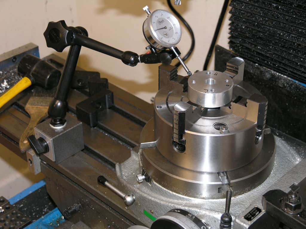
To get a really accurate, to dial indicate in the rotary table. In the photo it looks like the tip of the indicator is hanging in space, but it is actually touching the back of the hole in the rotary table. I then run the table through 360 degrees of rotation watching for the maximum deflection on the indicator. Then rotate the spindle 90 degrees to the left and 90 degrees to the right. The true center will be half way between the two readings.
For the final adjusting for centering that on the same side of the backlash as will be using when cutting. So if the cutter moves from the center to the right side, then want the cutter moving in the same direction when doing the center adjustment. If on the wrong side of the backlash, then well be overcompensate and start over now coming from the correct side.
Centering the jig or workpiece over the center of the rotary table. To do this, rotate the rotary table and adjust the work piece until I get consistent run out all the way around.
Often it is necessary to perform a rotary table operation on several identical workpieces, each having a machined hole in the center. To quickly align each workpiece, a special plug can be made to fit the center hole of the workpiece and the hole in the rotary table. Once the machine spindle has been aligned with the rotary table, each succeeding piece can be aligned quickly and accurately by placing it over the plug.
If there are only a few pieces, which would not justify the manufacture of a special plug, or if the workpiece does not have a hole through it center, the following method can be used to center the workpiece on the rotary table.
6. With a soft metal bar, tap the workpiece(away from the indicator movement) until no movement is registered on the indicator in a complete revolution of the rotary table.
To mill the end on the workpiece to a certain radius or to machine circular slots having a definite radius, following procedure below should be followed.
6. Mount the workpiece on the rotary table, aligning the center of the radial cuts with the center of the table. A special arbor may be used for this. Another method is to align the center of the radial cut with a wiggler mounted in the machine spindle.
rotary filing—that is, running a circular cutter withfile-like teeth in the headstock of alathe.Rotary filling and later,true milling were developed to reduce time and effort

·Typical use cases include machining the flutes of a milling cutter, cutting the teeth of a gear, milling curved slots, or drilling a bolt hole circle around the circumference of a part.


 8613371530291