
milling a radius on a rotary table factory

This website or its third-party tools process personal data (e.g. browsing data or IP addresses) and use cookies or other identifiers, which are necessary for its functioning and required to achieve the purposes illustrated in the cookie policy. To learn more, please refer to the cookie policy. In case of sale of your personal information, you may opt out by sending us an email via our Contact Us page. To find out more about the categories of personal information collected and the purposes for which such information will be used, please refer to our privacy policy. You accept the use of cookies or other identifiers by closing or dismissing this notice, by scrolling this page, by clicking a link or button or by continuing to browse otherwise.

2. Depending on the type of mill, round column or knee, provide enough head space to indicate the center of the rotary table and still get a cutter to the workpiece.
3. Mount your part. If the part is irregular shaped sometimes it"s easier to make up a mounting plate to fasten the part to. This way you can move the part to center and then clamp the plate in place.
6. For a part similar to what you"re showing you will also need to have a layout line that runs across the piece. Once you have the part on center square up the layout line by rotating the table as you move from end to end on the layout line. (with a wiggler)
9. Move one axis off center and then move the table back toward the part until the cutter starts to cut. Before you cut you should know what calculated degree of angle you will need to stop the radius at. This will be the blend point between the radius and the straight wall.
10. Start cutting your radius. Generally I stay about 1/2 degree away from my tangent point until I get the radius to where I want it. This will prevent the cutter from digging in and leaving a mark where the tangent point is. After you have the radius milled rotate the table to the appropriate angle and mill the straight sides. There will be a small amount of stock where you stayed shy of the angle when cutting the radius.
11. Now for your final cut, rotate the table so that your straight cut will be a climb cut. Take a finish pass along the straight wall until you axis dial reads -0-. Rotate the table the required amount until you get to the other tangent angle, lock the rotary table and then make your final straight cut.

1. Build a fixture that will locate the aluminum on the rotary table so I can repeatedly use the same setup without indicating for each of the 4 corners on each piece and each of the pieces in the lot. The fixture will also hold the work piece about 1/4" above the table surface to keep it from being damaged during machining.
3. Bolt that fixture to the rotary table such that each piece to be cut will be located with the center-line of the corner radius right on top of the rotational center of the table.
7. Advance the table further left some to avoid taking too big of cut and drop the quill down so the end mill will cut the entire thickness of the 1/4" aluminum on each pass.
Anyway...I"m a beginner at all of this and this is just what I came up with in my head. Hoping someone has a better way! (i.e. an easier way). These aluminum pieces are decorative...and they need to look right but really tolerances aren"t all that critical.

When using a rotary table on a Milling Machine, whether to mill an arc or drill holes in some circular pattern, there are two things that must be done to set up the workpiece. First, the workpiece must be centered on the rotary table. Second, the rotary table must be centered under the spindle. Then the mill table can be moved some appropriate distance and you can start cutting.
You could center the table under the spindle first, by indicating off the hole in the center of the table. Then you could mount the workpiece on the table and indicate off the workpiece. There are two problems with this approach. First, you are assuming that the hole in the table is true and centered. That may or may not be true. Second, this approach risks a sort of accumulation of errors, as you’re measuring from two different features (the rotary table’s hole and some feature on the workpiece). First center the workpiece on the rotary table, and then center the rotary table under the spindle.
To center the workpiece on the rotary table, spin the rotary table and watch for deflection of the indicator pointer. Adjust the position of the mill table(X and Y) as required, until the needle no longer deflects.
You dial in a rotary table by placing a dial test indicator in a chuck or collet in the spindle, which is then rotated by hand with the indicator tip in contact with the hole of the rotary table. If your machine can be taken out of gear, it helps to do so, so the spindle swings freely. It’s obviously easier to use a drill chuck than a collet, too, so you have something that you can turn easily. Make your adjustments using the saddle and table hand wheels.
Once you have center located (the indicator will read the same as you rotate the spindle, it’s a very good idea to set both of your dials at “0”, instead of marking some random location. Make sure you have backlash set properly, too. Set the dial is reading in a positive direction so it’s easy to count off any changes, and you never have to remember which way you had chosen to set backlash. I also always mark the table and saddle with a wax pencil so I know where center is located. That tells you when to stop turning the handle when “0” comes around if you want to get the table back to center to load another part.
Once you have located center of the table and have set dials and locked the table and saddle, you usually have some feature on your part that you desire to be centered. In some cases it may be a hole, in others it may be the outside edge of the circular part. In a case like either of these, it’s common practice to use the same indicator and swing it inside the hole or the perimeter of the part. The perimeter may require you to get around clamps, which can usually be accomplished by using the quill to move the indicator up far enough to clear them. When you dial in parts to a table that has already been located, you tap the part around, you do not make adjustments with the saddle or table handles. Tap the part after you’ve snugged up the clamps slightly, so it doesn’t move about wildly. You can achieve virtually perfect location that way, certainly as close as the machine is capable of working.
After the workpiece is centered on the rotary table, you now turn the spindle by hand, so the indicator tip sweeps the inside of the hole. Adjust the position of the mill table as required until no needle deflection is noted.

Agree with John that it will work just fine but setting up will be more than a chore if you need a decently accurate ball curve rather than a simple blending radius. Even with a simple radius setting needs to be pretty good if the results aren"t to appear a bit wonky. The Mk1 human eyeball is good at spotting such errors. If going for a full good ball it can be very hard to keep straight where remaining errors are and what adjustment corrects them once you"ve got to the "fairly good but not good enough" stage.
If you have a boring head with sufficient travel the "cut with the work and spindle axes at 45° to each other" works well and probably has a lower frustration index.
That said if you have a boring head it can be used as a basis for an effective up"n over type ball turning tool without a vast amount of work. Assuming you have a reasonable starter lump in the useful bits box I"d estimate that a very useable up"n over tool could be made in less than twice the average time taken to set-up what you propose and produce a nice workpiece. One made you have the up"n over tool ready to go at any time but the rotary table on the mill has to be set from scratch for each use.

To me, this table is just the right size and weight, not so small as to be a mere toy, but not too large, heavy, and expensive for my simple needs. I have had it for three weeks now and decided to review it after completing my first project.
When I first examined it I noticed that is seemed very well made and operated very smoothly. It definitely exceeded my expectations. I noticed it had a backlash of 20 minutes of arc, which I considered this totally acceptable. Accurate work is always done by turning knobs in one direction only. This table has a convenient knob to hold the position when it is reached. You can set the angle to about 1 minute of arc, and hold it there.
For my first project I made a couple of simple fixtures. One was a centering hold down, the other was an aluminum sub base. This is especially useful for mounting the table vertically in my drill press cross vise.
The project itself was a 2" diameter hub to mount an 8" sanding disc to a 1/2" shaft. The hub has 6 holes that I wanted to lay out precisely. Three holes run through the rim for set screws to hold the shaft. Three holes through the face attach the disc to the hub. Pictures of the hub and fixtures are attached.
Imagine the table is free to move in the X direction (i.e. by removing the the handle drive plate). [like disconnecting the cross slide of a lathe for taper turning]
It is then possible to arrange a radius arm A (say 12" long) with a fixed pivot at one end attached to the mills body and a pivot at the other end fixed to the table.
Attach a third arm C to drive the table from arm B at a point 1/10 along its length (see diagram - not to scale) and now as the carriage moves in the Y direction the table will prescribe an arc that ten times the radius of arm A (i.e 10")

rotary filing—that is, running a circular cutter withfile-like teeth in the headstock of alathe.Rotary filling and later,true milling were developed to reduce time and effort

A rotary table used in conjunction with a mill allows a machinist to produce virtually any part they can design. Sherline’s rotary table is a precision piece of equipment that has been designed to work with their vertical milling machines. However, it can be used on any mill whenever the small 4-inch size would be an advantage. The only limits are size, not complexity.
The table is 2″ high and 4″ (100mm) in diameter. The main components have been machined from solid bar stock steel, and the complete unit weighs seven pounds. The table has been engraved with a laser, giving sharp and precise lines every 5°, numbered every 15°. These lines are calibrated with the 72-tooth worm gear that is driven by the handwheel. The handwheel is divided into 50 parts, making each line on the handwheel 1/10°. This allows a circle to be divided into 3600 increments without interpolation. Seventy-two revolutions of the handwheel rotate the table one revolution.
The rotary tables can hold more weight when they are not under a continuous load. Click on the Video tab above to see examples of different weights and uses for our rotary tables.
The table T-slots are identical to those used on the Sherline mill and lathe, making the vast line of Sherline tooling available for use with this product. Two hold-down clamps and T-nuts are provided with the table. Also included is an adapter that allows Sherline’s 3- and 4-jaw chucks to be screwed directly to the rotary table. An optional right-angle attachment is available (P/N 3701) to mount the table in the vertical position to increase its versatility further. With the table mounted vertically, an optional adjustable right-angle tailstock (P/N 3702) can be mounted to the mill table. It is used to support and stabilize the other end of long work held in a chuck or otherwise attached to the rotary table.

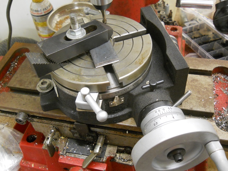
No expert here, but I"ve already learned the hard way that the setup you show will not work. You need to A) realise that the cutting forces at play are very large, B) that metal on metal doesn"t actually add up to that much friction, and C) you need something to stop the part from sliding rather than just holding it down.
At the very, very least, you could rotate the bar such that it was not over-top the T-slot. Then, you could bolt something in the T-slot such that the bar can push up against the side of it. Maybe do the same to the other end of the bar with the other T-slot. That way, when the endmill pushes into the bar, the bar will push against said bolt. Nothing to push against and it will just slide out of the way.
Better, as other"s have said, use 2 clamps, with the bolts holding said clamps down going up against the edge of your metal bar. Orientate them such that said bolts oppose the cutting forces. Then, all you have to worry about is the bar getting dragged out lengthwise.
It gets easier after a while... you clamp something down and, with experience, that little voice in your head goes "nope." Some days, you listen to that voice and find a better way
Rotary tables look cool and are fun to play with, but they"re finicky to get anything decent out of them. You have to zero the table in the mill, then zero the part on the table, and then get all the clamps in place but out of the way... Everything has to be really solid or the endmill will chatter and the cut will look lousy. Then you have to wind back and forth, back and forth... I"d scribe a line and abrade down to it with a belt sander, if I wanted a nice looking job. If I was in a rush, I"d probably just clamp an appropriate-sized washer to the end in a vice and then file up to it. Be done in less time than it would take to bolt the rotary table to the mill. There are so many ways to accomplish a given task.


 8613371530291